| CAMBIOS: | Reimpresión. |
| CHANGES | Reprint. |
AIRCRAFT STANDS CHARACTERISTICS
|
PRKG |
RAMP |
COOR |
EXIT |
MAX ACFT |
NOSE TO |
REMARKS |
|
1 |
– |
431817.84N 0025428.69W |
R |
B763 |
– |
400 Hz - A/C |
|
2 |
– |
431817.12N 0025426.32W |
R |
B763 |
– |
400 Hz - A/C Max Span 47,57m (1) |
|
3 |
– |
431816.16N 0025424.49W |
R |
B752 |
– |
400 Hz - A/C Max Span 38,05m (1) |
|
4 |
– |
431815.51N 0025422.67W |
R |
B752 |
– |
400 Hz - A/C Max Span 38,05m (1) |
|
5 |
– |
431815.00N 0025420.52W |
R |
B763 |
– |
400 Hz - A/C Max Span 47,57m (1) |
|
6 |
– |
431814.28N 0025418.18W |
R |
B764 |
– |
400 Hz - A/C INCOMP. 6A |
|
6A |
– |
431814.09N 0025417.98W |
R |
A35K/B744 |
– |
400 Hz - A/C INCOMP. 6 |
|
7 |
– |
431811.37N 0025416.26W |
A/R |
A21N/B3XM |
– |
INCOMP. 78 PUSH-BACK if PRKG 8 occupied. (2) |
|
8 |
– |
431810.12N 0025415.24W |
R |
A21N/B3XM |
– |
INCOMP. 78, 89 |
|
9 |
– |
431808.23N 0025414.88W |
A/R |
A21N/B3XM |
– |
INCOMP. 89 PUSH-BACK if PRKG 8, 11 occupied. (2) |
|
10 |
– |
431804.78N 0025416.59W |
A/R |
A21N/B3XM |
– |
INCOMP. 111 PUSH-BACK if PRKG 11 occupied. |
|
11 |
– |
431806.84N 0025415.95W |
R |
A21N/B3XM |
– |
INCOMP. 111 |
|
12 |
– |
431807.05N 0025413.80W |
A/R |
A21N/B3XM |
– |
INCOMP. H12 PUSH-BACK if PRKG 13 occupied. (3) |
|
13 |
– |
431807.84N 0025412.03W |
R |
A21N/B3XM |
– |
|
|
14 |
– |
431808.57N 0025410.39W |
A/R |
A21N/B3XM |
– |
PUSH-BACK if PRKG 13 occupied. (3) |
|
15 |
– |
431808.85N 0025409.06W |
R |
A21N/B3XM |
– |
INCOMP. 15A |
|
15A |
– |
431808.92N 0025408.10W |
A |
G450 |
– |
INCOMP. 15 |
|
16 |
– |
431809.89N 0025409.72W |
R |
A21N/B3XM |
– |
INCOMP. 16A |
|
16A |
– |
431809.95N 0025408.82W |
A |
G450 |
– |
INCOMP. 16 |
|
17 |
– |
431811.11N 0025410.80W |
R |
A21N/B3XM |
– |
INCOMP. 17A |
|
17A |
– |
431811.22N 0025409.98W |
A |
G450 |
– |
INCOMP. 17 |
|
18 |
– |
431812.19N 0025412.21W |
A/R |
A21N/B3XM |
– |
Simultaneous exit incompatible with PRKG 19 PUSH-BACK if PRKG 17 occupied. (2) |
|
19 |
– |
431814.09N 0025413.2948W |
A |
G450 |
– |
Simultaneous exit incompatible with PRKG 18 |
|
20 |
– |
431817.50N 0025435.27W |
A/R |
A21N/B3XM |
– |
PUSH-BACK if PRKG 21 occupied. (3) |
|
21 |
– |
431817.34N 0025433.68W |
R |
CRJ9 |
– |
Max span 24m |
|
22 |
– |
431817.63N 0025432.12W |
A/R |
A21N/B3XM |
– |
INCOMP. H22 PUSH-BACK if PRKG 21 occupied. (3) |
|
78 |
– |
431811.24N 0025415.88W |
R |
B763 |
– |
INCOMP. 7, 8 |
|
89 |
– |
431808.61N 0025414.02W |
R |
A359 |
– |
INCOMP. 8, 9 |
|
111 |
– |
431804.97N 0025415.56W |
A |
A35K/B744 |
– |
INCOMP. 10, 11 |
|
H12 |
– |
431806.56N 0025413.39W |
A |
S61 |
– |
INCOMP. 12 |
|
H22 |
-- |
431817.04N 0025432.07W |
A |
S61 |
-- |
INCOMP. 22 |
|
Remarks: |
|
|---|---|
|
(1) |
ACFT model without winglets. |
|
(2) |
Towed exit for aircraft larger than A20N/B38M. |
|
(3) |
Towed exit for aircraft larger than CRJ2. |
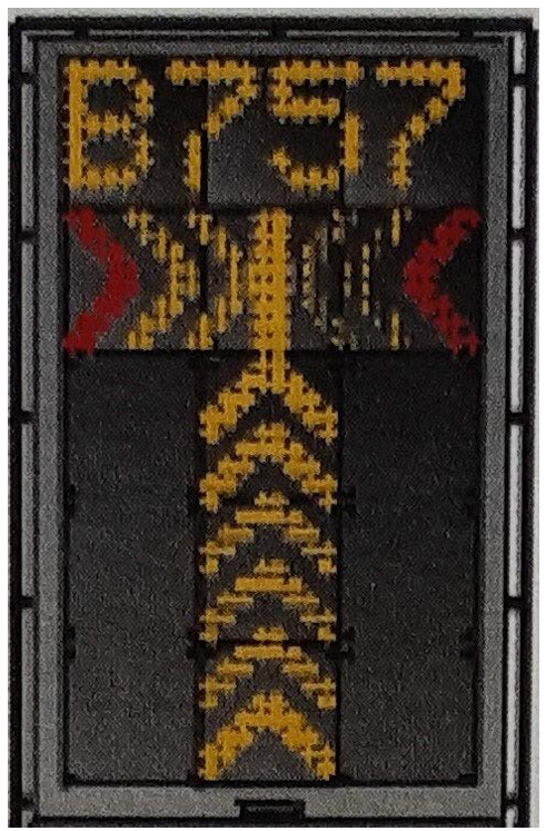
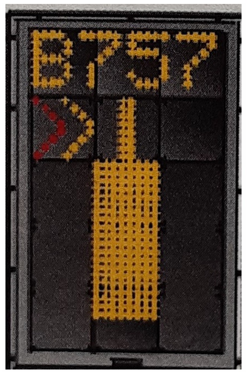
VISUAL DOCKING GUIDANCE SYSTEM
GENERAL
The North apron has a Visual Docking Guidance System (SVGA) on stands 1 to 6A. The information shown by this system contains azimuth guidance (shows the aircraft position in relation to the centre line of the parking area), and distance to the stop position (based on measurement by a radar laser), provided by a display unit mounted in front of the aircraft cockpit.
DISPLAY UNIT
This consists of:
-
One alphanumeric display line of 4 characters made up of yellow LEDs, which may show a variety of information: stand number (when the guidance is not activated), aircraft type, docking start (WAIT TEST), excess approach speed (SLOW DOWN), stop position (STOP), aircraft parked in correct position (OK), stop position overshot (TOO FAR), aircraft detection failure (WAIT), aircraft identification fault (STOP and ID FAIL), docking interrupted (STOP SBU), docking system visibility reduced by weather conditions (DOWN GRADE).
-
One line with one yellow LED module and 2 red/yellow LED modules to indicate the azimuth of the aircraft and when to stop.
-
One central column of 3 yellow LED modules to indicate the distance to the stop point.
GENERAL ADVICE
If the docking guidance system is not activated, the pilot must follow the manual instructions of the signalman.
If the pilot is unsure of the information shown on the display unit, they should stop the aircraft immediately and obtain more information before proceeding.
The pilot should not enter the parking point zone until after the docking system is displaying moving vertical arrows. The pilot must not pass the boarding bridge unless these arrows have been replaced by the approach rate bar.
The pilot shall not enter the parking point area unless the type of aircraft shown is the same than the one of the aircraft approaching.
The message STOP SBU means that the docking has been interrupted, and it may only be resumed under manual guidance. Do not attempt to resume docking without manual guidance.
INSTRUCTIONS TO THE PILOT
1) Check that the aircraft type shown is correct and the floating arrows are displayed.
2) Taxi along the centre line, observing the central guidance line.
When the aircraft has been captured by the laser, the floating arrows are replaced by the yellow centre line indicator.
3) Observe the azimuth guide to obtain the correct direction and position. A flashing red arrow indicates which way the aircraft should turn. An absence of direction arrows signifies that the aircraft is on the centre line.
Once the aircraft is within 16 m of the stop point, the approach rate is indicated by the progressive switch-off of one row of LEDs in the central column for every 0.7 m covered by the aircraft towards the stop point.
4) If one aircraft approaches the stop point at a higher speed than that programmed, the system displays the message SLOW DOWN to warn the pilot, and speed should be reduced.
5) When the correct stop position is reached, the display unit will show the message STOP and two red bars will light up. When the aircraft is parked, the message OK will be shown.
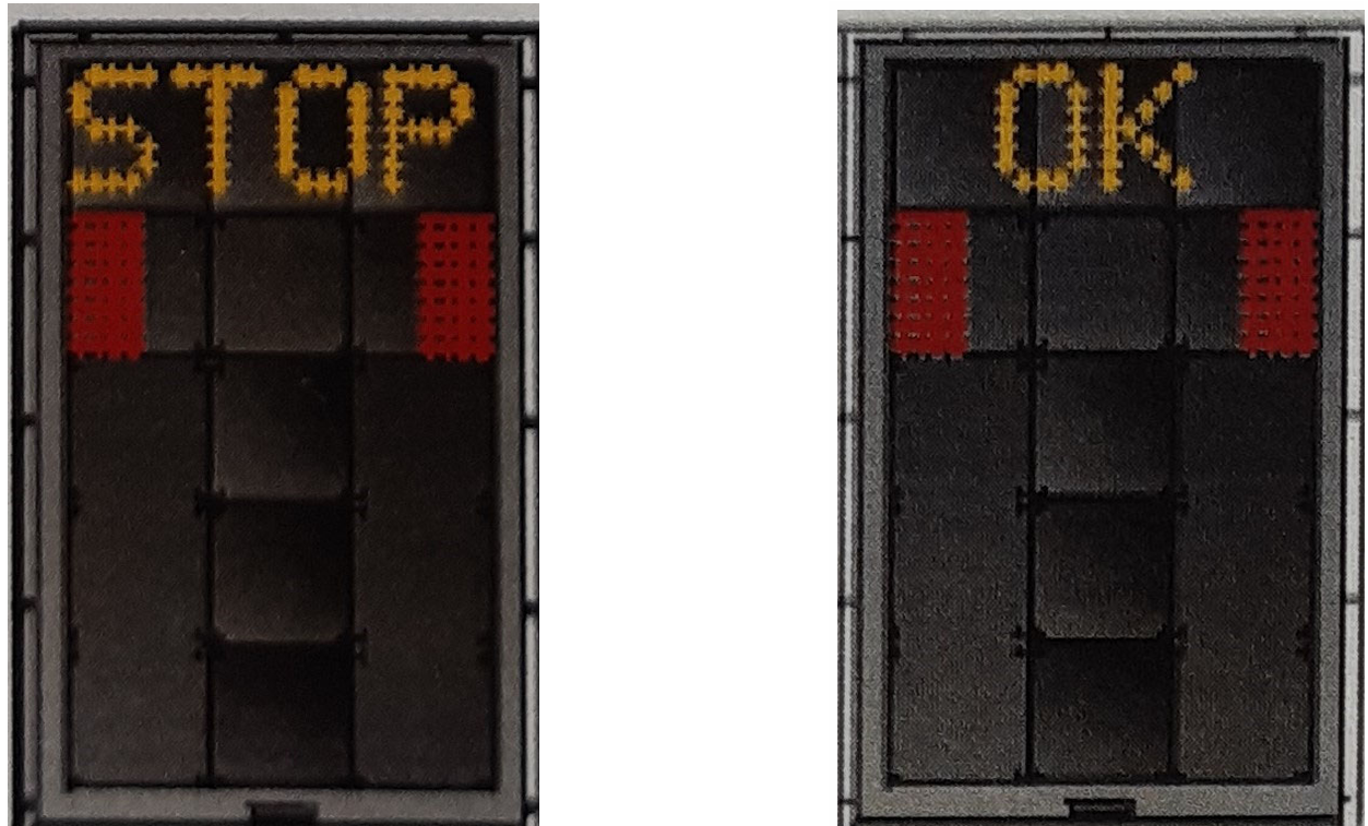
If the aircraft overshoots the stop point, the message TOO FAR appears.
6) If the aircraft detected is lost during the docking sequence, 12 m before STOP, the display unit will show WAIT. The docking procedure will continue as soon as the aircraft is detected anew.
7) During entry to the parking point, the type of aircraft will be verified. If, for any reason, the aircraft is not verified 12 metres before the stop point, the display unit will show STOP and ID FAIL.
8) During heavy fog, rain or snow, the visibility of the docking system may be reduced. When the system is activated and is in capture mode, the display unit will deactivate the floating arrows and show the message: "DOWN GRADE". As soon as the system detects an approaching aircraft, this message will be replaced by the approach rate bar.
The pilot should not pass the passenger boarding bridge unless the message "DOWN GRADE" has been replaced by the approach rate bar.