CHANGES: |
REPRINTING. |
AIRCRAFT STANDS CHARACTERISTICS
PRKG |
RAMP |
COORD |
EXIT |
MAX_ACFT |
NOSE_TO |
REMARKS |
|---|---|---|---|---|---|---|
7 |
– |
285705.90N 0133627.65W |
A/R |
B752 |
SW |
– |
8 |
– |
285707.02N 0133621.87W |
A/R |
AT72 |
SW |
– |
9 |
– |
285708.05N 0133621.27W |
A/R |
AT72 |
SW |
– |
10 |
– |
285709.21N 0133620.78W |
R |
A21N/B38MB3XM |
SW |
– |
11 |
– |
285710.98N 0133619.67W |
R |
B753 |
– |
– |
12 |
– |
285712.65N 0133618.83W |
R |
B763 |
NE |
– |
13A |
– |
285714.62N 0133617.79W |
R |
B763 |
NE |
INCOMP. 13B, 13C |
13B |
– |
285714.07N 0133618.07W |
A/R |
AT72 |
– |
INCOMP. 13A |
13C |
– |
285715.14N 0133617.45W |
A/R |
AT72 |
– |
INCOMP. 13A |
14 |
– |
285717.41N 0133615.97W |
R |
B744 |
NE |
– |
15 |
– |
285715.55N 0133611.79W |
A |
B752 |
– |
– |
15H |
– |
285715.19N 0133610.97W |
A |
S61 |
– |
(1) |
16 |
– |
285711.39N 0133613.61W |
A |
B39M |
– |
– |
16H |
– |
285711.19N 0133613.16W |
A |
S61 |
– |
(1) |
17 |
– |
285709.74N 0133614.70W |
A |
A20N |
– |
– |
18 |
– |
285708.49N 0133615.42W |
A |
A20N |
– |
– |
19 |
– |
285706.28N 0133616.66W |
A |
A21N/B38MB3XM |
– |
– |
19H |
– |
285706.36N 0133616.03W |
A |
B412 |
– |
(1) |
20 |
– |
285703.02N 0133618.69W |
A |
A21N/B38MB3XM |
– |
See item 20 |
21 |
– |
285701.60N 0133619.65W |
A |
A21N/B38MB3XM |
– |
See item 20 |
22 |
– |
285659.98N 0133620.57W |
A |
A21N/B38M |
– |
– |
23 |
– |
285658.15N 0133621.63W |
A |
B752 |
– |
See item 20 |
24 |
– |
285654.04N 0133623.21W |
A |
B753 |
– |
– |
24H |
– |
285652.90N 0133624.30W |
A |
S61 |
– |
(1) |
AG1 |
– |
285718.79N 0133615.59W |
– |
– |
– |
(2) |
AG2 |
– |
285719.38N 0133615.35W |
– |
– |
– |
(2) |
AG3 |
– |
285719.97N 0133615.01W |
– |
– |
– |
(2) |
AG4 |
– |
285719.13N 0133613.14W |
– |
– |
– |
(2) |
T1 |
– |
285657.04N 0133629.79W |
R |
B744 |
NE |
400 Hz – A/C |
T2 |
– |
285658.91N 0133628.40W |
R |
B763 |
NE |
400 Hz – A/C |
T3 |
– |
285700.62N 0133627.39W |
R |
B753 |
SW |
400 Hz – A/C, INCOMP. T7 |
T4 |
– |
285702.04N 0133626.48W |
R |
B753 |
SW |
400 Hz – A/C, INCOMP. T7 |
T5 |
– |
285703.38N 0133625.79W |
R |
A21N/B38MB3XM |
SW |
400 Hz – A/C |
T6 |
– |
285704.79N 0133625.39W |
R |
A21N/B38MB3XM |
SW |
400 Hz – A/C |
T7 |
– |
285701.13N 0133627.23W |
R |
A343 |
SW |
400 Hz – A/C, INCOMP. T3, T4 |
Remarks: |
|
(1) |
HEL MAX wingspan 22.5 m. |
(2) |
MAX wingspan 15 m. |
GENERAL
The system SAFEDOCK contains information about azimuth guidance (shows the aircraft position with relation to the centre line of the parking area) and distance to the stop position (based on a laser radar measurement), that is provided by a display unit, in front of the cockpit.
DISPLAY UNIT
Consists of:
-
WAIT TEST, ID FAIL and DOWN GRADE.
-
One line with a unit of yellow LED and 2 units of red/yellow LED for indication of aircraft azimuth and stop indication.
-
One column of 3 units of yellow LED in the centre to indicate the distance to the stop position.
PILOT INSTRUCTIONS
GENERAL ADVICE:
When the pilot is not sure about the information showed in the display unit, must inmediately stop the aircraft and obtain more information to proceed.
1. DOCKING START
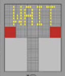
When the system starts, it shows the flashing message WAIT TEST.
2. CAPTURE
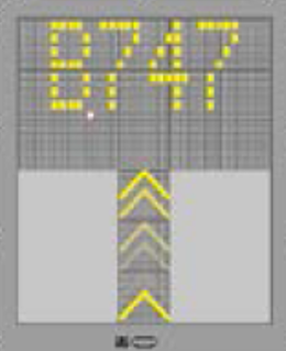
When the system is working in capture way. looking for the approaching aircraft, the system shows a vertical floating arrows. In the first line of the display unit will show the AIRCRAFT TYPE. ADVICE: If the system does not show a vertical arrows in movement and an aircraft type like the approaching
3. MONITORING
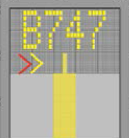
When the aircraft has been captured by the laser, the floating arrows are substituted by the yellow indicator in the centre line. A flashing red arrow shows the pilot the direction of turn in order to line-up along the stand edge. If the system does not show the direction arrows, it means the aircraft is over the centre line.
4. APPROACH RATE
When the aircraft is less than 16 m from the stop point, the approach rate is showed by one LED line turn-off from the centre line each 0,7 m covered when the aircraft moves until the stop position.
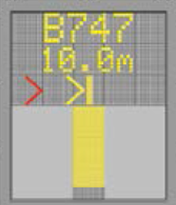
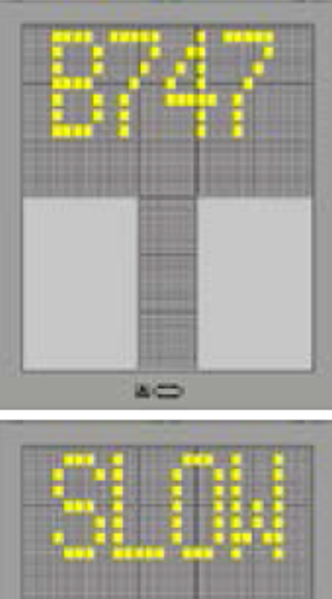
5. SPEED REDUCTION
If the aircraft speed exceed 3 m/seg. the unit display indicates “SLOW”; the entry speed must be reduced.
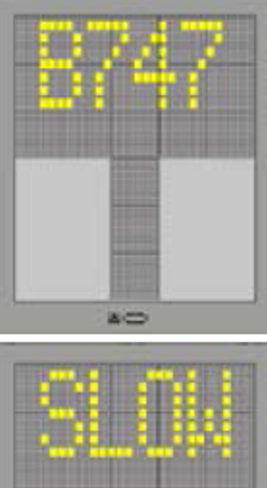
6. REACHING STOP POINT
When the correct stop point is reaching, the display unit shows STOP and lights red bars turns-on.
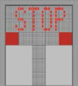
7. DOCKING FINISHED
When the aircraft is parked, the display unit shows OK.
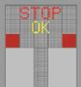
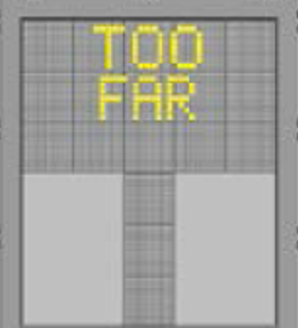
8. EXCEEDED
When the aircraft exceeds the stop point, the display unit shows TOO FAR.
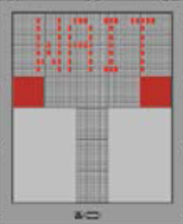
9. WAIT
When the detected aircraft is lost during the docking routine, 12 m before the STOP point, the display unit will show WAIT. The routine will continue when the system detects the aircraft again.
10. ADVERSES METEOROLOGICAL CONDITIONS
When the system visibility is reduced due to any reason, the downgrade mode will show the aircraft type and SLOW and floating arrows are disabled. As soon the system identifies the aircraft, the display unit will show the rate approach bar in order to continue the docking routine.
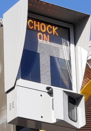
11. PLACEMENT AND RETRACTING OF THE BOARDING BRIDGE.
The airbridge may be docked when the chocks are in place and the message "CHOCK ON" is activated on the docking panel, which shall be visible for 60 seconds.
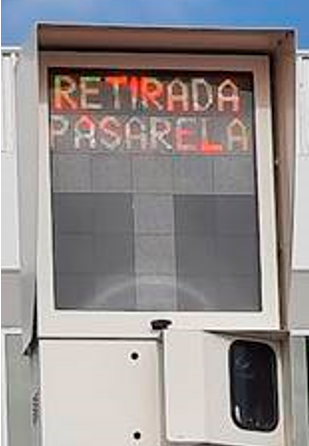
The airbridge may be retracted when the message “RETIRADA PASARELA” is activated on the docking panel, which shall be visible for 60 seconds.
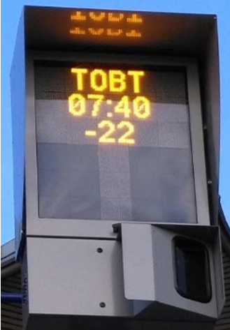
12. TOBT (Target Off Block Time) / TSAT (Target Start-up Approval Time)
TOBT will be shown in the display once the “CHOCK ON” message has disappeared, for a period prior to the programmed departure time (45 minutes for wide bodies and 30 minutes for the rest). Text TOBT, the time TOBT and corresponding negative countdown, are shown until 5 minutes before that time.
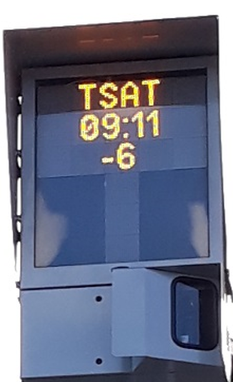
At that moment, will be shown in the display the messages TSAT/hh:mm/-mm (text/time TSAT/negative countdown until time TSAT)