GCFV AD 2 AERODROME DATA
AERODROME LOCATION INDICATOR AND NAME
GCFV - FUERTEVENTURA
AERODROME GEOGRAPHICAL AND ADMINISTRATIVE DATA
ARP |
282710N 0135150W. See AD 2-GCFV ADC. |
|
Distance and direction from the city |
5 km SW. |
|
Elevation |
25 m / 83 ft. |
|
Geoid undulation |
44.79 m ± 0.01 m. (1) |
|
Reference temperature |
28°C. |
|
Low average temperature |
18°C. |
|
Magnetic variation |
4°W (2020). |
|
Annual change |
6.6′E. |
|
AD administration |
Aena. |
|
Address |
Aeropuerto de Fuerteventura, 35600 Puerto del Rosario (Fuerteventura). |
|
TEL |
+34-928 860 600/500 |
|
FAX |
+34-928 860 530 |
|
AFTN |
GCFV |
|
Approved traffic |
IFR/VFR |
|
Remarks |
(1) For all AD points. |
OPERATIONAL HOURS
Airport |
V: 0600-2130 PS PPR 90 MIN BFR AD CLSD. |
||
Customs and Immigration |
HR AD. |
||
Health and Sanitation |
See item 5. |
||
AIS |
H24 (1) |
||
ARO |
H24 (2) |
||
MET briefing |
HR AD PS 1 HR BFR. |
||
ATS |
HR AD. |
||
Fuelling |
HR AD (3) |
||
Handling |
HR AD. |
||
Security |
H24. |
||
De-icing |
No. |
||
Remarks |
(1) Centralised AIO Office - International NOTAM Office
(2) Centralised ARO Office Geographical Area 15
GCFV AFTN address for fligh plan management: GCFVZPZX (3) Arriving aircraft: Aircraft refuelling will be permitted only if it is carried out within operational hours (PPR included). |
HANDLING SERVICES AND FACILITIES
Cargo facilities |
Elevator, MAX 2000 Kg. |
|
Fuel types |
JET A-1. |
|
Oil types |
No. |
|
Refuelling capacity |
JET A-1: 4 trucks, 3000000 L (each one),70 L/s; |
|
De-icing facilities |
No. |
|
Hangar space |
No. |
|
Repair facilities |
No. |
|
Remarks: |
It is mandatory to have a handling services for the following operations:
Ramp agents:
Ramp agents can serve both commercial aviation and general aviation. General Aviation Ramp agent: Fuel: |
PASSENGER FACILITIES
Hotels |
No. |
|
Restaurant |
Yes. |
|
Transportation |
Buses, taxis and hire cars. |
|
Medical facilities |
First aid service during limited hours. |
|
Bank/Post Office |
Cash dispenser/No. |
|
Tourist information |
Yes. |
|
Remarks |
None. |
RESCUE AND FIREFIGHTING SERVICES
Fire category |
9. (1) (2) |
|
Rescue equipment |
In accordance with the fire category published. |
|
Removal of disabled aircraft |
The Airport holds an array of slings, beams, inflatable bags, towing kits with load cell, ground reinforcement materials, aircraft tethering elements and crane, all of which permit hoisting and/or dragging any kind of aircraft permitted to operate at the Airport. Local contact details for unused aircraft transfer operations:
|
|
Remarks |
(1) The response time of the fire-fighting service to the end of RWY 01/19 is less than 3 minutes, with an operational target of less than 2 minutes. (2) The fire-fighting category may be downgraded during periods of slumps in traffic with very low percentage of higher-category aircraft as a result of a public health alert, and situations of category 7 or 5 are envisaged. This will be activated or deactivated by supplement or NOTAM. |
RUNWAY SURFACE CONDITION ASSESSMENT AND REPORTING, AND SNOW PLAN
Types of clearing equipment |
Not applicable. |
|
Clearance priorities |
Not applicable. |
|
Use of material for movement area surface treatment |
Not applicable. |
|
Specially prepared winter runways |
Not applicable. |
|
Remarks |
Runway surface condition assessment and reporting in accordance with the Global Reporting Format (GRF) methodology described in AD 1.2.2. Aerodrome in service during all seasons of the year. |
APRONS, TAXIWAYS AND CHECK LOCATIONS/POSITIONS DATA
| Apron | Surface: Hydraulic concrete, EXC PRKG 31 to 36B: asphalt. Strength: Commercial aviation apron: PCN 74/R/A/W/T, EXC PRKG 31 to 36B and associated helicopter PRKG: PCN 62/F/A/W/T. Cargo & General Aviation apron: PCN 89/R/A/W/T. |
|
| Taxiways | Width: 23 m, EXC T4 to T8: 45 m. Surface: Asphalt, EXC A1, B1, B2 and L1: hydraulic concrete. A2, A3, L2, L3 and L4: asphalt. Strength: L1: PCN 49/R/A/W/T. A1: PCN 74/R/A/W/T. A2, A3, L2, L3, L4: PCN 82/F/B/W/T. E5, E6, A4, A5 and L5: PCN 49/F/B/W/U. E1, E2: PCN 98/F/A/W/T. E4: PCN 120/F/A/W/T. |
|
| Check locations | Altimeter: Apron: 27 m / 88 ft, EXC PRKG 11–15: 30 m / 97 ft, and PRKG 51–60: 20 m / 65 ft. VOR: TWY A4 (282646.34N 0135203.36W), radial 354.35° and distance 0.921 NM. INS: See AD 2-GCFV PDC. |
|
| Remarks | (1) From the intermediate holding position near TWY L2 to the South. (2) From the intermediate holding position near TWY L2 to the North. TWY centre line: see INSIGNIA and Data Set. |
SURFACE MOVEMENT GUIDANCE AND CONTROL SYSTEM AND MARKINGS
| Taxiing guidance system | Boards, NO ENTRY boards, runway guard lights in TWY E1, E2, E9, E10 and T2; intermediate holding positions, runway-holding positions, stop bars, non-intrusion bars, visual guidance docking system and stand markings. | |
| RWY markings | Designators, threshold, displaced threshold, side stripe, centre line, aiming point, touchdown zone and rapid exit taxiway indicator markings for TWY E4 and E7. | |
| TWY markings | Centre line and side stripe. | |
| Remarks | None. |
AERODROME OBSTACLES
Obstacles which penetrate transitional, inner horizontal, conical, approach, inner transitional and take-off climb surfaces contained in Annex 14 of ICAO; and areas 2A and 3 contained in Annex 15 of ICAO |
See Item 10 and Data Set. |
|
Remarks |
See AD 2-GCFV AOC. RWY 01 approach surface is penetrated by aircraft and vehicles (mobile obstacles) taxiing on TWY T7 and T8, and by the ground itself. Aircraft and vehicles taxiing via TWY T1, E1 and E2 are obstacles for aircraft approaching to RWY 19. |
METEOROLOGICAL INFORMATION PROVIDED
| MET office | Fuerteventura EMAe. | |
| HR | HR AD PS 1 HR BFR AD CLSD. Outside this schedule, a half-hourly METAR AUTO will be issued. | |
| METAR | Half-hourly. | |
| TAF | 24 HR. | |
| TREND | No. | |
| Briefing | In person, by telephone and aeronautical meteorological self-service. | |
| Flight documentation/Language: | Charts and plain language / Spanish. | |
| Charts | Significant forecasted and wind and temperature in altitude maps. | |
| Supplementary equipment | Clouds image, lightnings and radar information display. | |
| ATS unit served | TWR, APP. | |
| Additional information | Las Palmas OMAe (GCGC): H24
Fuerteventura EMAe: HR AD
|
|
| Remarks | Aerodrome climatological summary available. Aerodrome warnings available. |
RUNWAY PHYSICAL CHARACTERISTICS
| RWY | Direction | DIM (m) | THR PSN |
THR ELEV TDZ ELEV |
SWY (m) | CWY (m) | Strip (m) | OFZ | RESA (m) | RWY/SWY SFC PCN |
|---|---|---|---|---|---|---|---|---|---|---|
| 01 (1) | 001.67° GEO / 005° MAG | 3406 x 45 | 282630.74N 0135150.84W | THR: 11.3 m / 37 ft TDZ: 20.3 m / 66 ft |
No | 60 x 150 (7) | 3526 x 296 (6) | Yes | 90 x 90 | RWY: ASPH — PCN 98/F/A/W/T (4) SWY: No |
| 19 (2) | 181.67° GEO / 185° MAG | 3406 x 45 | 282733.73N 0135148.76W | THR: 25.4 m / 83 ft TDZ: 25.4 m / 83 ft |
1000 x 45 (3) | 60 x 150 (8) | 3526 x 296 (6) | Yes | 90 x 90 | RWY/SWY: ASPH — PCN 98/F/A/W/T (5) |
Remarks: (1) THR RWY 01 displaced 1000 m. Coordinates RWY 01 end: 282748.87N 0135148.25W. (2) THR RWY 19 displaced 466 m. Coordinates RWY 19 end: 282558.27N 0135151.91W. (3) RWY 19: The last 1000 m are not usable for take-off, they are SWY. (4) RWY 01: first 1000 m PCN 105 F/B/W/T. (5) RWY 19: last 1000 m PCN 105 F/B/W/T. (6) Unpaved strip. Strip width 60 m before threshold of RWY 01 and first 1000 m of RWY 01: - right side of runway centre line and its extension throughout the length of the strip in the approach direction: 60 m. - left side of runway centre line and its extension throughout the length of the strip in the approach direction: 148 m. (7) 45 m symmetrical with respect to the runway centre line extension is paved, the rest is compacted natural soil. (8) 75 m symmetrical with respect to the runway centre line extension is paved, the rest is compacted natural soil. |
||||||||||
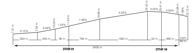
Profile
DECLARED DISTANCES
| RWY | TORA (m) | TODA (m) | ASDA (m) | LDA (m) |
|---|---|---|---|---|
| 01 | 3406 | 3466 | 3406 | 2406 |
| 19 | 2406 (1) | 2466 | 3406 | 2940 |
Remarks: (1) Because the last 1000 m are not usable for take-off. |
||||
APPROACH AND RUNWAY LIGHTING
| Runway | 01 | |
| Approach | Precision CAT I, 900 m. (1) Threshold identification lights. (4) | |
| PAPI (MEHT) | 3° (19.45 m / 64 ft). (1)(2)(3) | |
| Threshold | Green with wing bars. | |
| Touchdown zone | No. | |
| Runway centre line | 2406 m: 1506 m white + 600 m white and red + 300 m red. (1) Distance between lights: 15 m. | |
| Runway edge | 3406 m: 1000 m red + 1806 m white + 600 m yellow. (1) Distance between lights: 60 m. | |
| Runway end | Red. | |
| Stopway | No. | |
| Remarks | (1) Adjustable light intensity. Switch-on by radio outside AD operational hours on 118.475 MHz. (2) PAPI obstacle protection surface is penetrated by aircraft and vehicles (mobile obstacles) taxiing on TWY T7 and T8. (3) PAPI not available for aircraft B744 and code letter F aircraft. (4) White flashing lights. Rapid exit taxiway indicator lights (E4). |
| Runway | 19 | |
| Approach | Precision CAT I, 900 m. (1) Threshold identification lights. (3) | |
| PAPI (MEHT) | 3.45° (20.16 m / 66 ft). (1) | |
| Threshold | Green with wing bars. | |
| Touchdown zone | No. | |
| Runway centre line | 2940 m: 2040 m white + 600 m white and red + 300 m red. (1) Distance between lights: 15 m. | |
| Runway edge | 3406 m: 466 m red + 2340 m white + 600 m yellow. (1) Distance between lights: 60 m. |
|
| Runway end | Red. | |
| Stopway | No. (2) | |
| Remarks | (1) Adjustable light intensity.Switch on lighting by radio out of AD hours of operation available on 118.475 MHz. (2) Without lighting of its own, this is lit by RWY centre line and edge lights. (3) White flashing lights. Rapid exit taxiway indicator lights (E7). |
OTHER LIGHTING, SECONDARY POWER SUPPLY
| ABN/IBN | No. | |
| WDI | 1 near THR 01, 1 near THR 19, 1 RWY 19 end. LGTD. | |
| TWY lighting | Edge: E1, E2, E10, T2, T3, T4, T5, L4 and A5. Centre line: A4, A5, E1, E2, E9, E10, L1, L5, T1, T2, T3, T4, T5, T6, T7, T8 and only unidirectional of exit from RWY E3, E4, E5, E6, E7 and E8. |
|
| Apron lighting | 11 floodlighting poles: 9 in commercial apron and 2 in cargo and general aviation apron. | |
| Secondary power supply | Uninterruptible power supply for airfield lighting. Other
lighting systems: stand-by generators which offer a maximum
switch-over time (light) of 15 seconds. Switch-on by radio outside the operational hours of the AD available on 118.475 MHz for centre line lighting of TWY E1, E2, E3, T1 to T8, L1 and second floodlighting pole of ramp R3. |
|
| Remarks | None. |
HELICOPTER LANDING AREA
| Position | All helicopters other than those operated by the Guardia Civil on operational missions should use RWY 01/19 as FATO. | |||||||||||||||||||||||||
| Elevation | See item 12. | |||||||||||||||||||||||||
| Dimensions, surface, maximum weight, marking | See items 9 and 12. | |||||||||||||||||||||||||
| Direction | RWY 01/19 (see item 12). | |||||||||||||||||||||||||
| Declared distances | Declared distances, accessing/departing from RWY 01/19 via their threshold:
Declared distances, accessing/departing from RWY 01/19 via TWY E5:
|
|||||||||||||||||||||||||
| Lighting | See item 14. | |||||||||||||||||||||||||
| Remarks | Helicopters operated by the Guardia Civil on operational missions, may operate according to local procedure. |
AIR TRAFFIC SERVICES AIRSPACE
| Designation | CTR FUERTEVENTURA | |
| Lateral limits | 283751N 0135451W; 283748N 0134833W;283342N 0134836W; 283339N 0134300W;281839N 0134312W; 281845N 0135506W; 283751N 0135451W. | |
| Vertical limits | SFC-3500 ft AMSL. | |
| Airspace class | D. | |
Unit Language |
CANARIAS APP. ES/EN. |
|
| Transition altitude | 1850 m/6000 ft. | |
Hours of applicability |
- |
|
Remarks |
None. |
| Designation | ATZ FUERTEVENTURA | |
| Lateral limits | 283305N 0135455W; arc of 6.5 NM radius centred on ARP, clockwise to; 282118N 0135504W; 283305N 0135455W. | |
| Vertical limits | SFC-2500 ft AMSL. | |
| Airspace class | D. | |
Unit Language |
FUERTEVENTURA TWR. ES/EN. |
|
| Transition altitude | - | |
Hours of applicability |
- |
|
Remarks |
None. |
AIR TRAFFIC SERVICES COMMUNICATION FACILITIES
| Service | Call sign | FREQ | HR | Remarks |
|---|---|---|---|---|
| APP | Canarias APP | 129.300 MHz | HR AD | Canarias ACC |
| TWR | Fuerteventura TWR | 118.475 MHz 119.200 MHz 121.500 MHz 121.700 MHz 257.800 MHz 243.000 MHz |
HR AD HR AD HR AD HR AD HR AD HR AD |
— Secondary EMERG GMC MIL EMERG |
| ATIS | Fuerteventura INFORMATION | 118.650 MHz | HR AD | — |
| D-ATIS | Fuerteventura INFORMATION | NIL | HR AD | Provision of ATIS information via data link. |
RADIO NAVIGATION AND LANDING AIDS
| Facility (VAR) | ID | FREQ | HR | Coordinates | DME ELEV | Remarks |
|---|---|---|---|---|---|---|
| DVOR (4°W) | FTV | 114.100 MHz | H24 | 282550.8N 0135152.2W | — | COV to 40 NM BTN:
R-302 COV at:
At 10 NM & 3500 ft AMSL oscillations greater than ±2° BTN R-260/R-265. |
| DME | FTV | CH 88X | H24 | 282551.3N 0135152.2W | 0 m | COV to 40 NM BTN:
R-302 COV at:
|
| DME | FUE | 108.000 MHz/CH 17X | H24 | 282256.9N 0135158.2W | 30 m | COV 25 NM AVBL BTN:
|
LOC 01 (4°W) ILS CAT I |
IFV | 109.500 MHz | H24 | 282754.6N 0135148.1W | — | 005° MAG/644 m FM THR 19. COV 17 NM (15.4 NM DME) AVBL BTN −30°/+35° FM RCL ABV 2600 ft AMSL. |
| GP 01 | — | 332.600 MHz | H24 | 282639.0N 0135146.6W | — | 3°; RDH 15.54 m; at 257 m FM THR 01 & 108 m FM RCL to the right on APCH direction. |
| ILS/DME 01 | IFV | CH 32X | H24 | 282639.0N 0135146.6W | 18 m | REF DME THR 01. COV 17 NM (15.4 NM DME) at 2600 ft AVBL BTN −27° & +35° FM RCL. |
LOC 19 (4°W) ILS CAT I |
IFA | 111.300 MHz | H24 | 282552.8N 0135152.1W | — | 185º MAG/1168 m FM THR 01. COV 17 NM (15.5 NM DME) BTN −35°/+30° FM RCL AVBL at 3000 ft AMSL or ABV. COV 25 NM (23.5 NM DME) BTN ±10° FM RCL AVBL at 4500 ft AMSL or ABV. |
| GP 19 | — | 332.300 MHz | H24 | 282724.0N 0135145.4W | — | 3.45°; RDH 15.19 m; at 297 m FM THR 19 & 100 m FM RCL to the left on APCH direction. U/S FM 10 NM BLW 2200 ft AMSL. |
| ILS/DME 19 | IFA | CH 50X | H24 | 282723.9N 0135146.0W | 30 m | REF DME THR 19. COV 17 NM (15.5 NM DME) BTN −35°/+20° FM RCL AVBL at 3000 ft AMSL or ABV. |
| NDB (4°W) | FV | 397.000 kHz | H24 | 282257.3N 0135158.4W | — | 185° MAG / 6573 m FM THR 01; COV 25 NM. |
LOCAL AERODROME REGULATIONS
Banner-towing operations are not allowed.
The regularly scheduled operation of aircraft whose characteristics are above the airport reference code (code letter E) is not allowed.
Aircraft without RNAV1 GNSS aproval, whose destination outside Canarias, should inform TWR at the moment of engine start-up.
OPERATIONAL SAFETY REPORTS
Pilots/operator shall report to the airport as soon as possible regarding any accidents, incidents, occurrences or events that may have a potential operational impact in which they have been involved or have witnessed.
The purpose of these reports is to compile information in order to improve operational safety, independently of the compulsory report of the occurrence to the appropriate aeronautical authority.
Data may be sent in any format, including at least the following information:
- Date and time.
- Location.
- Parties involved (data used to identify vehicles, aircraft, etc. involved)
- Companies implicated.
- Description of the facts
- Any other data considered relevant (e.g. lighting conditions, weather, phase of the operation such as take-off/landing/stopover, pavement conditions, etc).
The airport e-mail address for operational safety reports is the following:
Seguridad_operacional_FUE@aena.es
In addition to notifying the airport by the means indicated, at least basic details of the accident, incident, occurrence or event must be sent to the air traffic control service provider (ATC).
PERSONNEL MOVEMENT IN APRON
Any movement on foot shall be upon the pedestrian tracks marked on the service roads outside the apron and only in the cases permitted by local regulations. General and Business Aviation may carry out internal transfers of personnel, Terminal - CEOPS Office - Aircraft, by vehicle, with a handling agent authorised to do so. The use of a vehicle is compulsory for transfers to Ramp 1 and Ramp 2B.
OPERATIVE INSTRUCTIONS
RUNWAY OPERATIONS
TWY E6, only for runway exit, is limited to aircraft type B737/A320 and below. TWY E5 is only allowed as runway exit for aircraft type B737/A320 and below, and as runway access for helicopters with prior ATC authorization.
RUNWAY ENTRY OPERATIONS
Aircraft are not authorized to access runway via TWY E3, E4 nor E6 to E8. Aircraft, except helicopters with prior ATC authorization, are not authorized to access runway via TWY E5. (There are information markings and boards).
A switched-off stop bar at a runway access does not imply authorization to enter the same if not also accompanied by the corresponding verbal ATC clearance.
STANDARD TAXIING PROCEDURES
The stop bars located at runway entry taxiways E1, E2, E9 and E10 are operated throughout the aerodrome operational hours and under all weather conditions.
Aircraft are authorized to pass the runway holding positions marked at TWY T6 and L5 provided that VMC hold at the Airport.
Back track manoeuvres in runway are not authorized for any type of aricraft.
Taxiing limitations:
- TWY E3, E4 and E6 to E8 are only usable for RWY 01/19 exit. TWY E5 is only usable for RWY 01/19 exit, except for helicopters with prior ATC authorization.
- TWY B3: only for air taxiing of Guardia Civil helicopters.
- TWY E2 and E9: restricted to code letter D or lower aircraft.
- TWY A4: restricted to code letter C or lower aircraft.
- With RWY 01 in use, the “FOLLOW ME” vehicle shall wait for the aircraft in TWY T2, near the intersection with TWY L1.
- With RWY 19 in use, the “FOLLOW ME” vehicle shall wait for the aircraft in TWY T7, near the intersection with TWY L5, for general aviation or cargo traffic; or in TWY T6, near the intersection with TWY L4, for commercial aviation traffic. In any case, if the visibility is not good, they may go to the exit of the appropriate taxiway.
- Except as provided in the airport local regulations, in general:
- RWY 01 holding bay (TWY E9 and E10) Code letter E aircraft cannot coincide simultaneously with any other aircraft model. Code letter D aircraft cannot either coincide simultaneously with code letter D aircraft.
- RWY 19 holding bay (TWY E1 and E2) Code letters D and E aircraft cannot coincide simultaneously with any other aircraft model.
- A345, A346, A350, B773, B778, B779 not authorized to taxi by TWY E3, E4, E7 and E8.
- A333, A339, B772not authorized to taxi by TWY E4, E7 and E8.
- A330, A343, A345, A346, A350, B773, B778, B779 not authorized to taxi by TWY L5 and A5.
All large aircraft, especially code letters E and F ones, must strictly follow the taxiway centre line markings except in turnings where it is necessary to perform oversteer manoeuvres.
All code letter E aircraft must perform oversteer manoeuvres on taxiways in the apron, turnings between TWY T and L and between TWY L and A, both when exiting and entering.
A345, A346, A35K and B77W aircraft shall perform oversteer manoeuvres on TWY E10 towards the runway entry.
Access to stands from taxiways may require the accomplishment of oversteer manoeuvres.
There exist intermediate holding positions on the runway exit taxiway E3, E4, E5, E6, E7 and E8, at the level of their intersections with Tango taxiway, which are not applicable to aircraft, only vehicles.
1. START-UP OF ENGINES/JETS.
Note: This section uses abbreviations defined in ENR 1.5.
The use of reverse thrust to leave the stands is forbidden, unless expressly cleared by Airport Authority.
The use of power higher than idle for starting up engines is forbidden at all towed push-back aircraft stands.
To avert the automatic cancellation of flight plans, the EOBT must be maintained up-to-date.
A.Permission to start up engines/jets shall be requested on the frequency stated via ATIS or CLD message. When this permission is requested, the aircraft must be completely ready to start up immediately.
B.For requests by voice, pilots must indicate the full aircraft call sign to ATC, together with the stand occupied and the ATIS message received.
C.Start-up clearance shall be requested:
- Aircraft without assigned CTOT: From 15 minutes prior to their EOBT, until 15 minutes after their EOBT.
- Aircraft with assigned CTOT: From 20 minutes prior to their CTOT until 10 minutes prior to their CTOT.
- To improve the predictability of the TTOT, ATC may issue instructions for start-up clearance to be requested at a specific time.
- In periods of high demand, ATC may apply other values which guarantee compliance with the tolerance window of the flight.
1.1 ATC CLEARANCE REQUEST AND START-UP VIA DATA LINK
DCL departure procedures are applied at Fuerteventura Airport in the provision of ATC clearance and start-up services. For more information on the DCL service, see AIP ENR 1.5, section 3. DEPARTING FLIGHTS, ATC clearance and start-up via data link (DCL).
In the event of any discrepancy, voice communications will always prevail over data link.
The pilot may request ATC clearance via DCL no earlier than 30 minutes before the EOBT. Approval of start-up jointly with ATC clearance will be facilitated provided that the parameters established in AD 2-GCFV, item 20, General taxiing procedures, 1.A and 1.C, are satisfied.
- The pilot shall request ATC clearance and start-up
simultaneously via RCD. The RCD message shall contain the
following data:
- Call sign according to the submitted flight plan (FPL).
- Departure aerodrome.
- Parking position.
- Destination aerodrome.
- Letter of the ATIS information received.
- ICAO aircraft type.
Any free text sent via the RCD by the pilot will not be considered by ATC. Special requests shall always be made via voice communications.
- The pilot will receive a message of acceptance, “RCD RECEIVED”, or of rejection, “RCD REJECTED”. When an RCD message is received earlier than the ranges established in AD 2-GCFV, item 20, General taxiing procedures, the RCD will be accepted and the CLD will be sent with ATC clearance, asking the crew to call when the aircraft is ready and in accordance with their EOBT/CTOT. When an RCD message is received within the ranges established in AD 2-GCFV, item 20, General taxiing procedures, the RCD will be accepted and the CLD will be sent with ATC clearance and approval of start-up.
- In the case of acceptance, Fuerteventura Clearance will issue a
CLD message with the following fields:
- Aircraft call sign.
- Destination aerodrome.
- Assigned runway for departure.
- Departure procedure (SID). Note: The initial altitude will be that of the published SID.
- SSR code mode A (SQUAWK).
- ADT (Approved Departure Time). Note: ADT = CTOT of the flight, if applicable.
- Next frequency.
- Current ATIS information letter.
- Additional information, which will include start-up clearance or instructions to request it if the start-up approval parameters indicated in AD 2-GCFV, item 20 are not yet satisfied.
- When an FSM message of the type “REVERT TO VOICE PROCEDURES” is received, the data link communication will be deemed to have concluded and the revert to voice procedures will be applied.
- When the CLD message is received, the pilot:
- If any inconsistency is detected in the received message, the pilot must revert to voice procedures and request a new clearance.
- If the pilot considers the CLD clearance message to be correct, he/she must respond via data link with a CDA message.
- If the pilot is not ready for start-up, he/she shall not accept the clearance and shall contact the controller by voice when ready.
- If a CDA message is not received by the pilot within the waiting time, or a CDA that is inconsistent with the previous CLD message is received, the data link communication will be terminated and a “CDA REJECTED” message will be received in the FMS.
- When a correct CDA message is received, the ATC system will send the aircraft a “CLEARANCE CONFIRMED” message in the FMS and will terminate the data link communication.
- Push-back must be requested on the frequency stated in the appropriate CLD message, and it may only be approved via voice on that frequency.
1.2 REVERT TO VOICE PROCEDURES
Upon receiving a message of the type “REVERT TO VOICE PROCEDURES”, or in the event of any inconsistency in the clearance received, the pilot will contact the controller by voice and request a new clearance.
1.3 EXCHANGE OF DATA WITH NMOC – ADVANCED ATC TWR
The Fuerteventura airport exchanges information for departure flights by applying the Advanced ATC TWR procedures.
Message exchanges from the local system to the ATM network uses the European standard for A-CDM airports, using the following message types:
- A-DPI for all instrumental departure flights.
- C-DPI when required.
When start-up is approved and the aircraft starts to exit the stand, the target take-off time (TTOT) is calculated and transmitted to NMOC (Network Manager Operations Center) via an A-DPI message. The use of the actual off-block time (AOBT) instead of the EOBT of the flight plan, along with the variable taxiing time, increases the precision of the take-off time.
After reception of the A-DPI, flight plan data must not be modified via DLA or CHG messages. If regulated, the CTOT assigned before receiving the A-DPI shall be maintained.
If an aircraft has to abort taxiing for technical reasons, the airport shall send a C-DPI message to the NMOC. The result of the C-DPI is that the flight plan shall be suspended by informing the operator via an FLS message with the comment “Suspended by Departure airport”. The flight plan can be activated again by updating the EOBT with a DLA or CHG message.
2. PUSH-BACK MANOEUVRING AND TAXIING
In all stands with autonomous exit, the exit manoeuvre shall be carried out at the minimum power required to initiate taxiing.
Autonomous exit from PRKG 52 to TWY A4 crossing PRKG 51 is authorised following the markings provided, after verification that the zone is clear of obstacles.
3. POWERBACK OPERATIONS
Powerback operations require prior authorization from Aerodrome Management and shall be executed under the sole responsibility of the aircraft operator.
This type of operation is only allowed for:
- Turboprop aircraft smaller than or equal to the dimensions of the AT72: the request and authorization shall be managed in real time.
- Turboprop aircraft larger than AT72 dimensions; the company agent must request this operation in advance from the E-mail: Seguridad_Operacional_FUE@aena.es .
The airport shall analyze the safety of the operation and the noise pollution caused by it.
4. HELICOPTER TAXIING
- There are no air transit routes defined.
- Helicopters are only authorized to taxi using TWY E1 to E10, T1 to T8, L1, A1, L5 and B3, although TWY B3 is exclusively for air taxiing by Guardia Civil helicopter operations.
- The helicopters are not authorized to overfly airport buildings.
- ATC may establish further restrictions on helicopter taxiing based on local procedures.
APRON TAXIING ROUTES
1. RWY 01 OPERATIONS (NORTH CONFIGURATION)
Apron arrivals: Provided the taxiing routes are blocked and alternative routes must be taken following the signalman at all times, the following routes shall be followed:
- Commercial apron
- PRKG from 11 to 17: TWY L1 - TWY A1 - assigned stand.
- PRKG from 18 to 22B: TWY L2 - A2 - assigned stand.
- PRKG from 23 to 27: TWY L3 - A3 - assigned stand.
- PRKG 28: TWY L4 - PRKG 28.
- PRKG 31 to 36 (EXC PRKG 33B, 34B, 35B and 36B): FM TWY T3 - assigned stand.
- PRKG 33B, 34B, 35B and 36B: TWY L1 - A1 - assigned stand.
- PRKG from 41 to 44: FM TWY T4 - assigned stand.
- PRKG from 45 to 47: FM TWY T5 - assigned stand.
- Cargo apron:
- PRKG 51: FM TWY A5 - PRKG 51.
- PRKG from 52 to 56: TWY B1 - assigned stand.
- PRKG from 57 to 60: TWY B2 - assigned stand.
In the North configuration, code letter C aircraft or lower are advised to pass via TWY L4, and may opt to access via TWY L5 if operations on the commercial apron are affected.
Apron departures: Provided the taxiing routes are blocked and alternative routes must be taken following the signalman at all times, the following routes shall be followed:
- Commercial apron
- PRKG from 11 to 18: assigned stand - TWY A1 - L2.
- PRKG from 19 to 24: assigned stand - TWY A2 - L3.
- PRKG from 25 to 28: assigned stand - TWY A3 - L4.
- PRKG from 31 to 36 (EXC PRKG 33B, 34B, 35B and 36B): assigned stand - TWY A1 - L2.
- PRKG 33B, 34B, 35B and 36B: assigned stand - direct TWY T3.
- PRKG from 41 to 44: assigned stand - TWY A2 - L3.
- PRKG from 45 to 47: assigned stand - TWY A3 - L4.
- Cargo apron
- PRKG 51: PRKG 51 - FM TWY A5.
- PRKG from 52 to 56: assigned stand - TWY B1.
- PRKG from 57 to 60: assigned stand - TWY B2.
2. RWY 19 OPERATIONS (SOUTH CONFIGURATION)
Apron arrivals: Provided the taxiing routes are blocked and alternative routes must be taken following the signalman at all times, the following routes shall be followed:
- Commercial apron
- PRKG from 11 to 12: TWY L1 - A1 - assigned stand.
- PRKG from 13 to 18: TWY L2 - assigned stand.
- PRKG from 19 to 24: TWY L3 - assigned stand.
- PRKG from 25 to 28: TWY L4 - A3 - assigned stand.
- PRKG from 31 to 36 (EXC 33B, 34B, 35B and 36B): FM TWY T3 - assigned stand.
- PRKG 33B, 34B, 35B and 36B: TWY L2 - A1 - assigned stand.
- PRKG from 41 to 44: FM TWY T4 - assigned stand.
- PRKG from 45 to 47: FM TWY T5 - assigned stand.
- Cargo apron
- PRKG 51: FM TWY A5 - PRKG 51.
- PRKG from 52 to 56: TWY B1 - assigned stand.
- PRKG from 57 to 60: TWY B2 - assigned stand.
Apron departures:
Provided the taxiing routes are blocked and alternative routes must be taken following the signalman at all times, the following routes shall be followed:
- Commercial apron
- PRKG from 11 to 18: assigned stand - TWY A1 - L2.
- PRKG from 19 to 24: assigned stand - TWY A2 - L3.
- PRKG from 25 to 28: assigned stand - TWY A3 - L4.
- PRKG from 31 to 36 (EXC 33B, 34B, 35B and 36B): assigned stand - TWY A1 - L2.
- PRKG 33B, 34B, 35B and 36B: assigned stand - direct TWY T3.
- PRKG from 41 to 44: assigned stand - TWY A2 - L3.
- PRKG from 45 to 47: assigned stand - TWY A3 - L4.
- Cargo apron
- PRKG 51: PRKG 51 - direct TWY A5.
- PRKG from 52 to 56: assigned stand - TWY B1.
- PRKG from 57 to 60: assigned stand - TWY B2.
3. HELICOPTERS
Apron arrivals:
- PRKG from H1 to H4, H7 and H8: FM TWY T3 - assigned stand.
- PRKG H5 and H6: TWY L1 - A1 - assigned stand.
Apron departures:
- PRKG H1 to H4, H7 and H8: assigned stand - direct TWY T3.
- PRKG H5 and H6: assigned stand - TWY A1 - L1.
RESTRICTIONS ON STANDS
1. GENERAL
- The use of 400 Hz facilities is mandatory at every stand where this service is available.
- The use of the air-conditioning facilities for aircraft is mandatory, whenever this service may be required, at every stand where this service is available.
- The use of the aircraft Auxiliary Power Unit (APU) is forbidden in all stands where the 400Hz / air-conditioning service is available, from 2 minutes after on-blocks to 5 minutes before off-blocks.
- The use of APU is only authorized when the 400 Hz facilities and the mobile power units are out of service, or when the air-conditioning service is required and the air-conditioning equipment is not available.
- Aircraft operating in autonomous stands should do so at the minimum power required.
- When an aircraft arrives with a broken APU, it is prohibited for it to keep the port engine switched on in apron during the stopover. Sole exception: B737 models may maintain this switched on (but switching off the starboard engine), and only while the ground energy supply services for the aircraft are disconnected. Prior communication to CEOPS (TEL: +34-928 860 518) at least one hour in advance is required from all aircraft operating at the airport whose APU is broken.
- Nosing to East is allowed to AT72 aircraft or below in PRKG 33B, 34B, 35B and 36B, according to local procedures.
2. GENERAL AVIATION
- Access to all the PRKG for general aviation, 54 to 60 should be carried out with the minimum taxiing speed possible.
3. HELICOPTERS
3.1 Taxiing to/from the PRKG for helicopters (H1 to H8) may be accomplished by ground or by air, except for the alignment and exit turning manoeuvres in the stand, which shall be accomplished mandatorily by air. Simultaneous independent helicopter operations are only permitted on ramp R1-B, to/from non-contiguous stands with the contiguous ones free.
Take-off/landing from/in these PRKG H1 to H8 are totally forbidden.
CODE LETTER F AIRCRAFT OPERATION
- The only code letter F aircraft that the airport accepts is 747-800. Code letter F aircraft arrival and stay at Fuerteventura airport requires prior airport authorization. Code letter F aircraft shall operate only occasionally in Fuerteventura airport and their operations cannot be scheduled on a regular basis.
- Aircraft shall not taxi by TWY T1 to T8 whenever a code letter F aircraft is landing or taking off.
- Whenever possible, code letter F aircraft take-off shall be performed with reduced power.
- No aircraft may be parked in the second row (PRKG 31 to 47 and H1 to H4, H7 and H8), nor may landing or departure operations be authorized, while a code letter F aircraft is taxiing.
- Code letter F aircraft shall taxi only by TWY T1 to T8, E1 and E10. If the runway configuration changes during the stopover, the aircraft may also be authorized to taxi via TWY E4 and E7. In all cases, airport workers will be required to perform procedural tasks in advance.
- Code letter F aircraft shall taxi following the centre line markings with their forward landing gear, whenever the accomplishment of an oversteer manoeuvre is not necessary, and shall taxi by taxiways at low speed, with their outer engines idling and taking special care while thrusting asymmetrically.
- A code letter F aircraft can only be parked on TWY T4, never on the apron. While parked there, aircraft become a fixed obstacle for other aircraft operations on RWY.
- Take-off operations for code letter F aircraft in low visibility conditions (LVC) are not allowed.
- The pilot of an aircraft shall not use the information provided by the PAPI, to avoid false indications during landing.
- Any movement of a code letter F aircraft via the taxiways (from vacating the runway after landing until it enters the same for take-off again), shall require the guidance of a “FOLLOW ME” vehicle.
- All code letter F aircraft should perform unmarked oversteer manoeuvres when using any TWY E, both for exiting and leaving the same, given that the widths of the taxiways are appropriate for code letter E aircraft.
NOISE ABATEMENT PROCEDURES
Overflying urban centres should be avoided as far as possible.
Sensitive areas to noise:
GENERAL
- The following restrictions shall be only applicable to jets.
- Except for safety reasons, all those aircraft must follow the noise abatement procedures indicates hereunder:
NOISE ABATEMENT PROCEDURES
TAKE-OFF
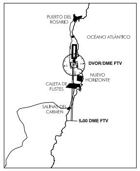
- Aircraft taking off from RWY 01 must follow the nominal flight path of the SID in use, not turning left before overflying point ADOVO.
- Aircraft taking off from RWY 19 must follow the nominal flight path of the SID in use, not turning right before 5.0 DME FTV.
LANDING
- Visual approach procedures and/or in contact with RWY 01 shall intercept the final approach segment at more than 5.0 DME FTV.
- Landing and approach procedures in visual meteorological conditions shall be performed with an angle equal to or higher than the ILS GP or PAPI of each runway.
GROUND ENGINE TEST
Engine test at higher than idling, may be performed from 0830 to 2100 hours, in the areas provided for that purpose; usually in North configuration, nosing to North in northern area of TWY T6 and in South configuration, nosing to South in southern area of TWY T6, always following instructions from TWR.
In exceptional cases, engine tests may be performed in the runway with prior authorization from the Airport Authority.
While the test is under way, it is mandatory to maintain permanent contact with TWR on GMC frequency.
Test shall be accomplished in accordance with the local procedure: FUE-OPS10-B, "ENGINE TEST”.
Requests for engine test clearance at any power, as well as any question regarding the engine testing procedure, must be addressed to:
- TEL: +34-928 860 518
- FAX: +34-928 860 836
CEOPS OFFICE
FLIGHT PROCEDURES
LOW VISIBILITY PROCEDURES (LVP)
Fuerteventura Airport does not have Low Visibility Procedures (LVP).
PROCEDURE FOR HALTING OPERATIONS IN THE MANOEUVRING AREA (PPOAM)
PROCEDURE FOR HALTING OPERATIONS IN THE MOVEMENT AREA FOR RVR < 550 m (PPOAM 550)
Fuerteventura Airport has a “Procedure for Halting Operations in the Manoeuvring Area for RVR under 550 m (PPOAM 550)” in order to maintain manoeuvring area safety in low visibility actions, which consists of the following phases:
PHASE I: WARNING
- To be initiated when:
- 800 m ≥ RVR ≥ 550 m.
- 1000 m ≥ ; VIS ≥ 800 m .
- Warning to all involved services and users for preparation.
PHASE II: HALTING OF OPERATIONS
- To be initiated when: RVR < 550 m or VIS < 800 m .
- TWR will not clear operations while these conditions remain, except special operations considered in the procedure.
- If visibility values recover to those of Phase I, said Phase I will be initiated.
PHASE III: PPOAM 550 CANCELLATION
- To be initiated when: RVR > 800 m.
- VIS > 1000 m.
- All associated procedures are cancelled.
Meteorological minimums defined for the procedure
| PHASES | RVR (m) | VIS (m) |
|---|---|---|
| PHASE I: WARNING | 800 ≥ RVR ≥ 550 | 1000 ≥ VIS ≥ 800 |
| PHASE II: HALTING OF OPERATIONS | RVR < 550 | VIS < 800 |
| PHASE III: PPOAM 550 CANCELLATION | RVR > 800 | VIS > 1000 |
SHORT COMMUNICATION PROCEDURE
ARRIVALS
In transfers of communications from the Sector NORTH-EAST of Canarias (FREQ 129.1) to Approach Canarias (FREQ 129.3), the initial call shall be limited to the flight CALL SIGN to avoid congestion on the frequency:
“Approach + Aeroflot 321”
DEPARTURES
To avoid congestion on the frequency in transfers of communications of traffic taking off from GCFV TWR to Approach Canarias (FREQ 129.3), the initial call shall be the name of the unit being called and the call sign of the calling aircraft:
“Canarias, Aeroflot 321, from GCFV”
RADAR DISPLAY SYSTEM
Above 200 ft AMSL, ATS surveillance systems may be used in supplying the aerodrome control service, for the following purposes:
- Supervision of the flight path of aircraft on final approach;
- Supervision of the flight path of other aircraft in the vicinity of the aerodrome, except for transits operating to the West of the airfield, to which it will be provided above 1000 ft;
- Giving navigation assistance to VFR flights except for transits operating to the West of the airfield, to which it will be provided above 1000 ft;
- Establishment of radar separation between successive departing aircraft above 400 ft AMSL.
Depending on the availability of the radars which provide coverage to the ATZ, the areas or heights for which the indicated uses of the radar are supplied may vary.
The aerodrome controllers shall maintain all the operations taking place at or in the vicinity of the aerodrome under constant visual surveillance, with access to an ATS surveillance system to support that visual observation, as stipulated in article 4.5.1.3. of the Reglamento de la Circulación Aérea. All of the foregoing shall depend on the limitations of the equipment.
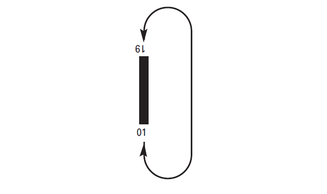
AD TRAFFIC CIRCUIT
ADDITIONAL INFORMATION
AREAS NOT VISIBLE FROM TOWER
The fire fighting service building prevents vision from the new Control Tower of certain parts of the manoeuvres area. See AD 2-GCFV ADC / GMC.
Vision from the Control Tower is aided by television cameras.
From time to time, ATC may request aircraft to notify when crossing the runway-holding position located in T2 segment of the parallel taxiway.
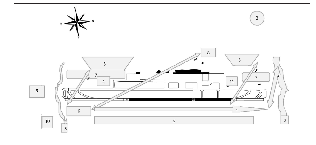
BIRD CONCENTRATION AREAS
- Area 1: Flow of crossing birds, generally seagulls from south-east to north-east, tending to deviate to the North and to Area 2.
- Area 2: Island rubbish tip and new road works, high concentration of birds perching and in flight.
- Area 3: Gullies delimiting the North and South of the airport.
- To the north: Concentrations of pigeons, herons, egrets, seagulls, Egyptian vultures, kestrels, ravens and buzzards.
- To the south: Gully which forms small marshes at its mouth, with concentrations of herons, egrets, seagulls and plover.
- Area 4: Sewage plant and recycling centre of the airport. Concentration of woodcock, herons, pigeons and turtle doves. Ducks occasionally.
- >Area 5: Urban centres with dovecots on flat roofs, concentration of flocks of pigeons in flight.
- Area 6: Coastal areas with concentration of perching seagulls in the middle of the day in winter and at any time in summer.
- Area 7: Wooded plant barriers, large concentration of turtledoves, pigeons and small birds.
- Area 8: Farm. Concentration of birds perched and in flight.
- Area 9: Golf courses south of the airport, concentration of seagulls and other birds.
- Area 10: Occasional caravanning area, seagull concentration.
- Area 11: Firefighters' drill area with pools that give rise to small flocks of sandgrouse, seagulls and pigeons.
WIND PHENOMENA
The orographical conditions of the airport setting and its location tend to lead to the appearance of wind shear and turbulence phenomena below 3000 ft under the following meteorological circumstances, so that, if any of them holds, an unstable approach, or even the need to miss, might be expected:
- In general, moderate or gusting winds.
- Winds in the first quadrant with thermal inversion.
- Winds in the fourth quadrant with speed equal to or greater than 10 kt.
- Light surface winds in the first or fourth quadrants, but with south component at 2000 ft.
- In the TAFOR, a forecast change in wind direction (TEMPO or BECMG) of greater than 120º with respect to the surface wind.
- Difference greater than 50º in the wind direction between the two thresholds and/or significant difference of the speeds between the two thresholds.
In addition, the following circumstances might also tend to lead to missed approaches:
- Effect of wind funnelling due to the presence of gullies close to both runway thresholds, especially in approaches to RWY 19.
- Impression of flying very high in approaches to RWY 19, due to the steep angle of descent required.
- Optical effect caused by the presence of runway margins twice as wide as usual, due to their characteristics.
- Effect caused by the relative proximity between the two thresholds (1940 m) of one much longer runway (3406 m), both at a lower altitude than the central zone.
AERONAUTICAL CHARTS RELATED TO AN AERODROME
The list of charts related to the aerodrome can be found on the link below:
VISUAL SEGMENT SURFACE (VSS) PENETRATION
The instrument approach procedures affected can be found below:
- IAC 1 ILS Z RWY 01: Direct approach.
- IAC 2 ILS Y RWY 01: Direct approach.
- IAC 3 ILS X RWY 01: Direct approach.
- IAC 4 LOC Z RWY 01: Direct approach.
- IAC 5 LOC Y RWY 01: Direct approach.
- IAC 6 VOR RWY 01: Direct approach.
- IAC 7 NDB RWY 01: Direct approach.
- IAC 8 RNP RWY 01: LNAV, LNAV/VNAV.
- IAC 9 ILS Z RWY 19: Direct approach.
- IAC 10 ILS Y RWY 19: Direct approach.
- IAC 11 ILS X RWY 19: Direct approach.
- IAC 12 LOC Z RWY 19: Direct approach.
- IAC 13 LOC Y RWY 19: Direct approach.
- IAC 14 VOR RWY 19: Direct approach.
- IAC 15 NDB RWY 19: Direct approach.
- IAC 16 RNP RWY 19: LNAV, LNAV/VNAV.