LEAL AD 2 AERODROME DATA
AERODROME LOCATION INDICATOR AND- NAME
LEAL - ALICANTE/Alicante-Elche Miguel Hernández
AERODROME GEOGRAPHICAL AND ADMINISTRATIVE DATA
ARP |
381656N 0003329W. See AD 2-LEAL ADC. |
|
Distance and direction from the city |
9 km SW. |
|
Elevation |
43 m / 142 ft. |
|
Geoid undulation |
50.0 m ± 0.05 m (1). |
|
Reference temperature |
31°C. |
|
Low average temperature |
11ºC. |
|
Magnetic variation |
1ºE (2020). |
|
Annual change |
7.2'E. |
|
AD administration |
Aena. |
|
Address |
Aeropuerto de ALICANTE/Alicante-Elche Miguel Hernández - 03195 El Altet (Alicante). |
|
TEL |
+34-966 919 000 |
|
AFTN |
LEAL |
|
Approved traffic |
IFR/VFR (2) |
|
Remarks |
(1) For all AD points. (2) Business and General Aviation Traffic (IFR/VFR) is subject to the declared capacity. Request slot from the scheduling coordination office or PPR 3 HR from CEOPS LEAL;
Aircraft type, registration marking, operator and the handling agent, departure and destination aerodrome, and date/time of ETA and ETD must be included. Flights without authorisation are not allowed. Due to air traffic safety reasons; from November 1st to March 15th:
Except: hospital, SAR, emergencies and State flights. From March 16th to October 31st:
Except: hospital, SAR, emergencies and State flights. (3) See item 20 Local Regulations. |
OPERATIONAL HOURS
Airport |
H24. |
|
Customs and Immigration |
H24. |
|
Health and Sanitation |
See GEN 1.4. |
|
AIS/ARO |
H24. (1) |
|
MET briefing |
H24. |
|
ATS |
H24. |
|
Fuelling |
H24. |
|
Handling |
H24. |
|
Security |
H24. |
|
De-icing |
No. |
|
Remarks |
(1) Centralised ARO Office Geographical Area 9.
Centralised AIO Office - International NOTAM Office
|
HANDLING SERVICES AND FACILITIES
Cargo facilities |
No limitations. |
|
Fuel types |
100LL, JET A-1. (1) |
|
Oil types |
AEROSHELL W100. |
|
Refuelling capacity |
No limitations. |
|
De-icing facilities |
No. |
|
Hangar space |
No. |
|
Repair facilities |
No. |
|
Remarks |
It is mandatory to have a handling agent for all operations, non-commercial operations included. For arrival operations, passengers and crews must wait for their handling agent. (1) Requests for fuel supply on the following numbers:
Ramp agents:
Globalia, Menzies Aviation and Aviapartner ALC ramp agents can serve both Commercial Aviation and General Aviation. |
PASSENGER FACILITIES
Hotels |
No. |
|
Restaurant |
Yes. |
|
Transportation |
Taxis, hire cars, buses. |
|
Medical facilities |
First aid, resting room. |
|
Bank/Post Office |
Banking machines/No. |
|
Tourist information |
Yes. |
|
Remarks |
None. |
RESCUE AND FIRE FIGHTING SERVICES
Fire category |
9. CAT 7 1600-2000, for CAT 9 in these hours PPR 20 min. |
|
Rescue equipment |
In accordance with the fire category published. |
|
Removal of disabled aircraft |
Crane trucks not belonging to AD, with a maximum raising capacity of 60 TM. The airport has its own specific equipment for elevating and towing aircraft, available to owners or commercial flight operators, including:
|
|
Remarks |
The response time of the rescue and fire fighting service is less than 3 MIN, with an operational objective of less than 2 MIN. |
RUNWAY SURFACE CONDITION ASSESSMENT AND REPORTING, AND SNOW PLAN
Types of clearing equipment |
Not applicable. |
|
Clearance priorities |
Not applicable. |
|
Use of material for movement area surface treatment |
Not applicable. |
|
Specially prepared winter runways |
Not applicable. |
|
Remarks |
Runway surface condition assessment and reporting in accordance with the Global Reporting Format (GRF) methodology described in AD 1.2.2. Aerodrome in service during all seasons of the year. |
APRONS, TAXIWAYS AND CHECK LOCATIONS/POSITIONS DATAMOVEMENT AREA DETAILS
Apron |
Surface: Concrete and asphalt. Strength: Stands: 1 to 2, D1, D2, D4, D5, E1 to E3 and TWY A and B to access apron: 3 to 7, D3, D6, E4 to E6, H1 to H5: PCN 58/R/A/W/T. 8, 9A, 10 to 12, 14, 16, 19, 81, 83, 85, 87, 89 and E7 to E9: 18, 20 and 22 to 29: PCN 68/R/A/W/T. 31 to 49, 200: PCN 62/R/A/W/T. TWY C to access apron: PCN 64/F/A/W/T. Apron inner taxiway: each section has the strength of the adjacent stands EXC BTN PRKG 31 and 49. |
|
Taxiways |
Width: 23 m, EXC: A2: 24.90 m. A4: 29.40 m. A5, C5: 29.70 m. A6: 29.60 m. C2: 24.10 m. C4: 27.40 m. C7: 28.40 m. C8: 28.10 m. C9: 23.70 m. Surface: Asphalt, EXC A4, A5, A6 and C5: Concrete. Strength: PCN 64/F/A/W/T, EXC: A4 and A6: PCN 78/R/A/W/T. A5 and C5: PCN 62/R/A/W/T. C3 intersection with C5: PCN 76/F/A/W/T. C4: PCN 115/F/A/W/T, PCN 80/F/A/W/T. C6 and section joining C8-C9 with runway: PCN 87/F/A/W/T. C8: PCN 96/F/A/W/T. C7 and C9: PCN 59/F/A/W/T. Joining section C7 with RWY: PCN 40/F/A/W/T. |
|
Check locations |
Altimeter: Apron: ELEV 28 m/92 ft EXC PRKG: 1A, 1B, 1C, 2, 3A, 3B, 4A: 33 m/108 ft. PRKG: 33, 200, 35, 36, 37, 39, 41, 43, 45, 47 and 49: 24 m/79 ft. VOR: No. INS: See AD 2-LEAL PDC. |
|
Remarks |
TWY centre line: see INSIGNIA and Data Set. |
SURFACE MOVEMENT GUIDANCE AND CONTROL SYSTEM AND MARKINGSTAXIING GUIDANCE SYSTEM AND MARKINGS
Taxiing guidance system |
Runway-holding positions, intermediate holding positions, stop bars, boards, NO ENTRY boards, runway guard lights, stands lights and NO ENTRY lights. |
|
RWY markings |
Designators, threshold, centre line, side stripe, touchdown zone, aiming point. |
|
TWY markings |
Centre line, side stripe. Spotlight markers on TWY edge EXC inner apron TWY. |
|
Remarks |
LED lighting systems: Intermediate holding positions, stop bars, runway guard lights and NO ENTRY lights. |
AERODROME OBSTACLES
Obstacles in Approach, Take-Off Climb, Conical, Inner Horizontal, Transitional, Inner Transitional and Balked Landing Surfaces established in ICAO Annex 14; and the areas 2A and 3 established in ICAO Annex 15. Those penetrating these surfaces are identified in the CSV file as “Relevante_Relevant = Si/Yes”.
|
See Item 10 and Data Set. |
|
Remarks |
See AD 2-LEAL AOC. |
METEOROLOGICAL INFORMATION PROVIDEDMETEOROLOGICAL SERVICE PROVIDED
MET office |
Alicante EMAe. |
|
HR |
H24. |
|
METAR |
Half-hourly. |
|
TAF |
24 HR. |
|
TREND |
Yes. |
|
Information |
In person and by telephone. |
|
Flight documentation/Language |
Charts and plain language/Spanish. |
|
Charts |
Forecast significant, and wind and temperature at altitude, maps. |
|
Supplementary equipment |
No. |
|
ATS unit served |
TWR, APP. |
|
Additional information |
Valencia OMAe (LEVA) H24
Alicante EMAe: H24
|
|
Remarks: |
Aerodrome climatological summary available. Aerodrome warnings available. |
RUNWAY PHYSICAL CHARACTERISTICS
RWY |
Direction |
DIM (m) |
THR PSN |
THR ELEV TDZ ELEV |
SWY (m) |
CWY (m) |
Strip (m) |
OFZ |
RESA (m) |
RWY/SWY SFC PCN |
|---|---|---|---|---|---|---|---|---|---|---|
10 |
100.04° GEO 100° MAG |
3000 x 45 |
381704.29N 0003429.96W |
THR: 43.2 m / 142 ft TDZ: 43.2 m / 142 ft |
No. |
60 x 150 (1) |
3120 x 280 (1) |
Yes. |
240 x 150 (2) |
RWY: ASPH (4) SWY: No |
28 |
280.06° GEO 280° MAG |
3000 x 45 |
381647.32N 0003228.42W |
THR: 13.2 m / 43 ft TDZ: No. |
No. |
60 x 150 (3) |
3120 x 280 (2) |
No |
240 x 150 (2) |
RWY: ASPH (4) SWY: No |
Remarks: (1) Asphalt. (2) Grass. (3) First 50 m of asphalt and last 10 m of grass. (4) From 0 m to 289 m from THR 10: PCN 51/F/A/W/T; |
||||||||||
Profile
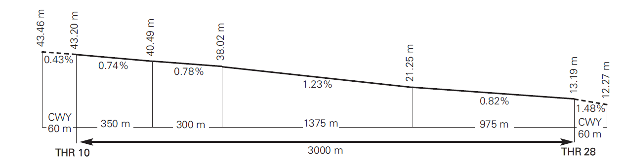
DECLARED DISTANCES
RWY |
TORA (m) |
TODA (m) |
ASDA (m) |
LDA (m) |
|---|---|---|---|---|
10 |
3000 |
3060 |
3000 |
3000 |
28 |
3000 |
3060 |
3000 |
3000 |
28 INT C5 |
2700 |
2760 |
2700 |
– |
28 INT C7 |
2927 |
2987 |
2927 |
– |
10 INT A4 |
2966 |
3026 |
2966 |
– |
Remarks: None. |
||||
APPROACH AND RUNWAY LIGHTING
Runway |
10 |
|
Approach |
Precision CAT I, 900 m. LIH. (1) (2) Threshold identification lights. |
|
PAPI (MEHT) |
3° (18.41 m/60 ft). (3) |
|
Threshold |
Green with wing bars. |
|
Touchdown zone |
No. |
|
Runway centre line |
3000 m: 2100 m white + 600 m white and red + 300 m red. LIH. (1) (2) Distance between lights: 15 m. |
|
Runway edge |
2400 m white + 600 m yellow. LIH. (1) (2) Distance between lights: 50 m. |
|
Runway end |
Red. (2) |
|
Stopway |
No. |
|
Remarks |
Rapid exit taxiway indicator lights (C2 and C4). (3) (1) Adjustable light intensity. (2) LED lighting. (3) PAPI not usable by B747 aircraft. |
Runway |
28 |
|
Approach |
Precision CAT I, 900 m. LIH. (1) Threshold identification lights. |
|
PAPI (MEHT) |
3° (20.72 m/68 ft). |
|
Threshold |
Green with wing bars. |
|
Touchdown zone |
No. |
|
Runway centre line |
3000 m: 2100 m white + 600 m white and red + 300 m red. LIH. (1) (2) Distance between lights: 15 m. |
|
Runway edge |
2400 m white + 600 m yellow. LIH. (1) (2) Distance between lights: 50 m. |
|
Runway end |
Red. (2) |
|
Stopway |
No. |
|
Remarks |
Rapid exit taxiway indicator lights (A2). (2) (1) Adjustable light intensity. (2) LED lighting. |
OTHER LIGHTING, SECONDARY POWER SUPPLY
ABN/IBN |
No. |
|
WDI |
1 near THR 10, 1 near THR 28. LGTD. |
|
TWY lighting |
Centre line EXC inner apron TWY. (1) |
|
Apron lighting |
18 floodlighting poles LIH. |
|
Secondary power supply |
Uninterrupted power supply (UPS) with a switch over time of 0 seconds, supported by engine generators with a maximum response time of 15 seconds. |
|
Remarks |
(1) LED lighting. |
HELICOPTER LANDING AREA
Position |
FATO: RWY 10/28. THR10 and THR 28 coordinates, see item 12. Ground taxiing: TLOF same as RWY 10/28. Coordinates 381656N 0003329W (same as ARP). Air taxiing: TLOF same as PRKG H1, H2, H3, H4 and H5. |
|
Elevation |
FATO: RWY 10/28. THR10 and THR 28 elevation, see item 12. Ground taxiing: TLOF same as RWY 10/28. Elevation 43 m. Air taxiing: TLOF same as PRKG H1, H2, H3, H4 and H5.
|
|
Dimensions, surface, maximum weight, marking |
FATO: RWY 10/28.
Circular strip of 50 cm width and inner diameter of 12.06 m. |
|
Direction |
No. |
|
Declared distances |
No. |
|
Lighting |
No. |
|
Remarks |
Dimensions MAX ACFT: See AD 2-LEAL PDC. |
AIR TRAFFIC SERVICES AIRSPACE ATS AIRSPACE
Designation |
CTR ALICANTE. |
|
Lateral limits |
382724.0N 0010234.0W; 382644.4N 0005830.3W; 382439.8N 0004544.5W; 382109.3N 0002415.1W; 381945.8N 0001543.2W; 380744.8N 0001207.0W; 380555.0N 0001226.4W; 380154.7N 0001608.4W; 380459.3N 0002528.8W; 380700.0N 0002800.0W; 380700.3N 0003138.2W; 380733.9N 0003320.9W; 380811.1N 0004145.0W; 381158.6N 0004130.0W; 381405.3N 0005637.0W; 381758.1N 0005941.2W; 381828.0N 0010122.2W; 382015.3N 0010227.4W; 382205.1N 0010146.0W; 382514.0N 0010348.0W; 382724.0N 0010234.0W. |
|
Vertical limits |
SFC-5000 ft AMSL. |
|
Airspace class |
D. |
|
Unit Language |
VALENCIA TACC. ES/EN. |
|
Transition altitude |
1850 m / 6000 ft. |
|
|
Hours of applicability |
- |
|
Remarks |
None. |
Designation |
ATZ ALICANTE. |
|
Lateral limits |
Airspace within the line joining 382345N 0003942W; 382119N 0002441W; 381000N 0002715W; 381207N 0004218W; 382345N 0003942W. |
|
Vertical limits |
SFC-2500 ft AMSL. |
|
Airspace class |
D. |
|
Unit Language |
ALICANTE TWR (1). ES/EN. |
|
Transition altitude |
- |
|
|
Hours of applicability |
- |
Remarks |
(1) Call sign: Alicante TWR. HR ATS: see item 3. |
AIR TRAFFIC SERVICES COMMUNICATION FACILITIESATS COMMUNICATION FACILITIES
Service |
Call sign |
FREQ |
HR |
Remarks |
|---|---|---|---|---|
APP |
Valencia Control |
118.800 MHz |
H24 |
APP/I |
119.075 MHz |
H24 |
BACK-UP |
||
120.400 MHz |
H24 |
APP/H |
||
TWR |
Alicante TWR |
118.155 C |
H24 |
- |
119.855 C |
H24 |
CLR |
||
121.500 MHz |
H24 |
EMERG |
||
122.100 MHz |
H24 |
MIL |
||
125.180 C |
H24 |
BACK-UP |
||
130.655 C |
H24 |
GMC |
||
243.000 MHz |
H24 |
EMERG |
||
257.800 MHz |
H24 |
MIL |
||
ATIS |
Alicante Information |
120.080 C |
H24 |
- |
D-ATIS |
Alicante Information |
NIL |
H24 |
Provision of ATIS information via data link. |
RADIO NAVIGATION AND LANDING AIDSRADIO NAVIGATION & LANDING FACILITIES
Facility (VAR) |
ID |
FREQ |
HR |
Coordinates |
DME ELEV |
Remarks |
|---|---|---|---|---|---|---|
VOR (1º E) |
ALT |
113.800 MHz |
H24 |
381605.8N 0003412.4W |
- |
R-003: possible needle oscillations of more than ± 2º BTN 6 NM & 10 NM. |
DME |
ALT |
CH 85X |
H24 |
381606.0N 0003412.2W |
60 m |
- |
DVOR (1º E) |
ATE |
114.650 MHz |
H24 |
381710.2N 0003512.0W |
- |
COV to 25 NM NO AVBL BTN:
|
DME |
ATE |
CH 93Y |
H24 |
381710.4N 0003512.6W |
60 m |
COV to 25 NM NO AVBL BTN:
|
LOC 10 (1º E) ILS CAT I |
IAT |
110.300 MHz |
H24 |
381645.6N 0003216.0W |
- |
100º MAG / 307 m FM THR 28; COV 17 NM AVBL BTN ± 35º FM RCL at 4600 ft AMSL or ABV. COV 25 NM AVBL BTN ± 10º FM RCL at 4600 ft AMSL or ABV. |
GP 10 |
335.000 MHz |
H24 |
381658.5N 0003415.9W |
- |
3º; RDH 15 m; at 367 m FM THR 10 & 118 m FM RCL to the right in direction APCH. COV 10 NM BTN +6º -4º FM RCL AVBL at 2200 ft AMSL or ABV. |
|
ILS/DME 10 |
IAT |
CH 40X |
H24 |
381658.5N 0003415.9W |
48 m |
REF DME THR 10. |
LOCAL AERODROME REGULATIONSLOCAL REGULATIONS
AIRPORT REGULATIONS
AD closed to aircraft without two-way radiocommunication.
AD closed to aircraft with piston engine in schedule: V: 0700-2400 (LT) I: 0800- 2200 (LT).
General aviation aircraft that intend to operate according to VFR rules in ATZ ALICANTE must be equipped with 8.33 kHz separation capacity systems in application of AIP-ESPAÑA ENR 1.8, as otherwise the operation is forbidden.
State aircraft with 8.33 kHz channel exemptions must communicate with Alicante TWR on the NATO frequency (122.100 MHz), and always with advance notice to the corresponding ATS units, because the frequency is not watched permanently.
Arriving flights will notify their exemption on the approach frequency.
Departing flights will inform Alicante TWR by telephone (+34-966 919 535) 30 MIN before their departure time.
PROCEDURES TO VACATE THE RUNWAY
-
Landing on RWY 10: only TWY C2, C4, C5, C7, C8 or C9 are available. TWY C2, C5 and C7 are exclusively for code letter C aircraft (MAX wingspan 36 m) or lower. A346, A35K and B77W aircrafts may only use C8.
-
Landing on RWY 28: only TWY A2, A4, A5 or A6 are available. TWY A4 is exclusively for code letter C aircraft (MAX wingspan 36 m) or lower. A346, A35K and B77W aircrafts may only use A5.
MINIMUN RUNWAY OCCUPANCY TIME
ARRIVALS
To make maximum use of the runway, reduce its occupancy time and the incidence of go-around, it is important for the pilot in command, without prejudice to the safety and normal operation of the aircraft, to adapt their landing manoeuvre to vacate the runway rapidly via:
-
Landings on RWY 28: TWY A2.
-
Landings on RWY 10: TWY C2 (code letter C or lower ACFT) or TWY C4 (code letters D, E or F ACFT).
-
During periods of high intensity runway use (announced in the ATIS), pilots shall report the exit taxiway to be used, in the landing read-back.
Aircraft that have already landed will report 'runway vacated' and the exit taxiway used. They will hold position waiting for taxiing instructions from ATC.
DEPARTURES
ATC will consider that every aircraft at the holding position is able to commence line-up on the runway and the take-off run immediately after take-off clearance is issued.
Pilots unable to comply with this requirement shall notify ATC before reaching the holding position.
Take-off operations from RWY 28 intersection with TWY C5 and C7 are allowed. And also from the intersection of RWY 10 with TWY A4 are allowed. See AD 2-LEAL item 13.
Limitations on departure operations through the holding positions of RWY 10:
-
TWY A4 is exclusively for CAT C aircraft (MAX wingspan 36 m) or lower.
-
A346, A35K and B77W aircrafts may only use A5 for access to the runway.
Limitations on departure operations through the holding positions of RWY 28:
-
TWY C5 and C7 are exclusively for aircraft with a maximum wingspan of 36 m.
-
A346, A35K and B77W aircrafts may only use C8 for access to the runway.
ATC PROCEDURES
TAKE-OFF FROM INTERSECTION
Aircraft requesting this procedure shall notify it, preferably, when requesting starting to taxi
GENERAL TAXIING PROCEDURES
START-UP OF ENGINES/TURBINES.
Note: This section uses abbreviations defined in ENR 1.5.
To avert the automatic cancellation of flight plans, the EOBT must be maintained up-to-date.
-
Permission to start up engines/turbines shall be requested on the clearance frequency or, if this is not attended, on the frequency stated via ATIS or CLD message. When this permission is requested, the aircraft must be completely ready to start up immediately.
-
For requests by voice, pilots must indicate the full aircraft call sign to ATC, together with the stand occupied and the ATIS message received.
-
Aircraft must comply with the provisions of section 6.3.
ATC CLEARANCE REQUEST AND START-UP VIA DATA LINK
Data Link departure procedures are applied at ALICANTE/Alicante-Elche Miguel Hernández Airport in the provision of ATC clearance and start-up services. For more information on the DCL service, see AIP ENR 1.5, section 3. DEPARTING FLIGHTS, ATC clearance and start-up via data link (DCL).
In case of discrepancies, voice communications will always prevail over data link.
The pilot may request ATC clearance via DCL from 30 minutes before their TOBT until 5 minutes after their TOBT.
-
The pilot shall request ATC clearance and start-up simultaneously via RCD. The RCD message (Departure Clearance Request) shall contain the following data:
-
Call sign according to the submitted flight plan (FPL).
-
Departure aerodrome.
-
Parking position.
-
Destination aerodrome.
-
Letter corresponding to the ATIS information received.
-
ICAO aircraft type.
Any free text sent via the RCD by the pilot will not be considered by ATC. Special requests will always be made via voice communications.
-
-
The pilot will receive a message of acceptance, “RCD RECEIVED”, or of rejection, “RCD REJECTED”.
-
In the case of acceptance, Alicante will issue a CLD message with the following fields:
-
Aircraft call sign.
-
Destination aerodrome.
-
Assigned runway for departure.
-
Departure procedure (SID).
-
Note: The initial altitude will correspond to the published SID.
-
SSR code mode A (SQUAWK).
-
ADT (Approved Departure Time).
-
Note: ADT = CTOT of the flight, if applicable.
-
Next frequency.
-
Current ATIS information letter.
-
Additional information, which will include start-up clearance or instructions to request it in the case of failure to comply with the start-up approval parameters indicated in AD 2, item 20, 6.3.
-
-
When a CLD message is sent in the valid range of TOBT and TSAT, ATC and start-up clearance will be received. If the pilot is not ready for start up, he/she shall not accept the clearance and shall contact the controller by voice when ready.
-
When an FSM message of the type “REVERT TO VOICE PROCEDURES” is received, the data link communication will be deemed to have concluded and the revert to voice procedures will be applied.
-
When the CLD message is received, the pilot:
-
If any inconsistencies in the received message are detected, the pilot must revert to voice procedures and request a new clearance.
-
If the pilot considers the CLD clearance message to be correct, he/she must respond via data link with a CDA message (Departure Clearance Echoback).
-
-
If a CDA message is not received by the pilot within the waiting time, or a CDA that is inconsistent with the previous CLD message is received, communication via data link will be terminated and a "CDA REJECTED" message will be received in the FMS.
-
When a correct CDA message is received, the ATC system will send the aircraft a "CLEARANCE CONFIRMED" message in the FMS and will terminate the communication via data link.
Push-back must be requested on the frequency stated in the appropriate CLD message, and it may only be approved via voice on that frequency.
REVERT TO VOICE PROCEDURES
Upon receiving a message of the type "REVERT TO VOICE PROCEDURES", or in the event of any inconsistency in the clearance received, the pilot will contact the controller via voice and request a new clearance.
GROUND MOVEMENT
Avoidance of collisions with other aircraft or obstacles is the responsibility of:
-
Pilots when taxiing on the apron.
-
Ground handling companies during the push-back manoeuvre or exit from the stand.
It is forbidden to cross the taxiways on foot to access the stands in the apron.
Access to the aircraft on foot will only be possible if parked in a stand next to the terminal building. Access to the other of stands shall be accomplished by vehicle.
After vacating the runway, if no taxiing instructions have been received, aircraft shall hold short of the taxiway parallel to the runway.
Guiding service by a "FOLLOW ME" vehicle is provided for General Aviation flights and aircraft bound for stands with docking guide U/S.
The guidance service will also be provided in cases when the apron pavement is wet, as well as upon request either by TWR or the pilot, or in exceptional cases.
Preferably, General Aviation shall use the gate A.
MD-11 aircraft shall perform `oversteering' manoeuvres when taxiing at Gate D, as the distance between the outer main gear wheel and the edge of the taxiway is less than 4.5 m.
The following are limited to use by aircraft with a maximum wingspan of 52 m:
-
Gate B.
-
The segment of the stand access taxiway between PRKG 6A and gate C.
-
East area of the apron, from PRKG 200, including the aircraft turn pads.
The following are limited to use by aircraft with a maximum wingspan of 65 m:
-
The segment of the stand access taxiway between PRKG 4C and gate A.
-
The segment between gates C and D.
-
The segment of taxiway giving access to PRKG 200.
On remote stands (second line) with autonomous exit, cross-bleed start (to start the second engine by means of bleeding the fisrt one) overseen by the vehicle “FOLLOW ME” is authorized subject to prior coordination with ATC.
This operation must be carried out increasing the power only to the minimum needed to start the rest of the engines.
The autonomous exit from those stands where it is allowed shall be carried out in such a way that, when turning, idling power is not exceeded.
Pilots will be responsible for carrying out the stand exit manoeuvre observing the Guidance System and leaving the apron through the first available gate to go to the runway in service, unless otherwise instructed by ATC.
All surface movements of aircraft, towed aircraft, personnel and vehicles on the manoeuvring area are subject to prior ATC clearance.
Ground Movement Control is responsible for:
-
Control of all aircraft, personnel and vehicle movements on the manoeuvring area, except for the runway.
-
Issuing approvals and instructions for towed push-back and taxiing of aircraft.
PUSH-BACK MANOEUVRING AND TAXIING
-
Aircraft must be ready for towed push-back at the approved start-up time; otherwise pilots will contact ATC. The time between the end of the towing manoeuvre and the beginning of taxiing must be 3 minutes, at the most.
-
At remote stands, aircraft must request taxiing instructions at most 3 minutes after receiving approval for start-up.
-
Push-back manoeuvres shall be accomplished as follows, unless Alicante Ground Movement Control advises differently:
-
RWY 10 in service: aircraft nosed to West.
-
RWY 28 in service: aircraft nosed to the East.
-
-
Exceptions:
-
PRKG 1A, always nosing towards the South.
-
PRKG 1B and 1C, always nosing towards the West.
-
PRKG 36, 37, to 49 will always nose to the South.
-
PRKG 200 will always nose to the West.
-
PRKG 33, 35, 87 and 89 will always nose to the East.
Regardless of the runway in service, aircraft parked on:
-
-
The exit for code letter E aircraft from PRKG 2 and 4C will always be carried out through gate A.
-
The use of gate A when departing is incompatible with the access to PRKG 2, as is the use of gate B with the access to PRKG 8.
-
Start-up of engines above idling at all stands in contact with the terminal is forbidden, until the aircraft is lined-up with the taxiway.
-
Runway-holding position and intermediate holding position markings: See AD 1.1.
-
Clearance for aircraft towing shall be requested from TWR on the appropriate frequency.
-
Simultaneous push-back from two adjoining positions shall not be cleared.
-
Simultaneous entry/exit from the following parkings shall not be permitted: 19-23; 23-25; 25-27; 29-31; 31-33; 33-35; 37-39; 39-41; 41-43; 43-45; 45-47; 47-49 y 4A-4B.
A-CDM PROCEDURE
DEFINITIONS
-
EOBT: Estimated Off-Block Time
-
NMOC: Network Manager Operations Centre
-
CTOT: Calculated Take-Off Time
-
TOBT: Target Off-Block Time. Time by which the air carrier or the ground handling agent expects to be ready, with the doors closed, airbridge disconnected and aircraft push-back equipment connected.
-
TSAT: Target Start-Up Approval Time. Estimated start-up time calculated based on the TOBT, taxi time from the stand, the CTOT (if subject to regulation) and the airport operational capability.
-
TTOT: Target Take-Off Time.
GENERAL
Alicante-Elche Miguel Hernández airport applies A-CDM processes in the aircraft departure sequence. The A-CDM processes start three hours prior to the estimated off-block time (EOBT) and end with aircraft take-off. Throughout the process, all flight-related information must be kept up-to-date. The information will be sent automatically to the Network Manager Operations Centre (NMOC) at Eurocontrol and will be used to improve management in assigning calculated take-off time (CTOT).
Alicante-Elche Miguel Hernández airport applies the FAM (Flight Activation Monitoring) system managed by Eurocontrol. To prevent flight plans from being suspended automatically, the EOBT and TOBT must be kept up-to-date until the request for start-up, following the TSAT, so that the traffic flow enables departure to occur as close to TTOT as possible.
PROCESS
Aircraft may request ATC clearance from 30 minutes prior to their TOBT, and may request start-up from 5 minutes prior to their TOBT until 5 minutes TSAT.
ATC clearance shall only be given between TOBT -30 minutes and TOBT -5 minutes.
On their callup (when not using data link), aircraft must:
-
Report the aircraft type and series, stand, and the ATIS message received;
-
Communicate the need to perform a cross-bleed start if required.
Between TOBT -5 and TSAT +5, the pilot shall request start-up. When possible (TSAT-5, TSAT+5), it shall be cleared. Then it is not possible, a start-up request shall be recorded in the A-CDM system and TSAT information shall be provided.
The start-up request log is equivalent to the REA message request for flights regulated with CTOT.
In case of non-compliance with A-CDM parameters, ATC shall not log the start-up request, and the pilot must contact his/her flight coordinator to correct A-CDM parameters.
Once the start-up request has been logged and TSAT information provided, in order to avoid saturating the frequency, pilots shall refrain from making additional calls before requesting start-up clearance in accordance with the updated TSAT.
If no start-up request is received within 5 minutes after TSAT, the flight will lose its TSAT and its start-up will not be cleared.
A new updated TOBT and EOBT shall be required in order to sequence the flight again and to receive a new TSAT.
The TOBT and/or EOBT may only be updated by the air carrier or by its ground handling agent, therefore pilots shall refrain from making requests of this nature to ATC.
HELICOPTER OPERATIONS
Helicopters shall be treated as fixed-wing aircraft and ATC will clear them to take-off and land in RWY 10/28.
TAXIING ROUTES
Taxiing will be carried out via the same taxiways used by fixed-wing aircraft.
This could be air or ground taxiing, depending on the helicopter type.
ARRIVALS
Helicopters arriving by RWY 10 will exit the runway via RET C2 up to the holding position of this taxiway, and will be authorized by ATC to taxi via TWY C1, B2 in direction West up to gate B, guided by the “FOLLOW ME” vehicle indications up to the assigned stand.
Helicopters arriving by RWY 28 will exit the runway via RET A2, and will be authorized by ATC to taxi via TWY A1 in direction East up to the holding position of this taxiway, and to enter through gate A, guided by the “FOLLOW ME” vehicle indications up to the assigned stand.
DEPARTURES
Departures for RWY 10 will be cleared by ATC to taxi from the stand to gate A and to proceed to the runway-holding position on TWY A5 via TWY A1, A3, where they will wait for ATC instructions to enter the RWY 10.
Departures for RWY 28 will be cleared by ATC to taxi from the stand to gate B and to proceed to the runway-holding position on TWY C8 via TWY B2, C1, C3, C6, where they will wait for ATC instructions to enter the RWY 28.
OPERATION OF CODE LETTER F AIRCRAFT
Although the operation of code letter F aircraft is not a regular operation in ALICANTE/Alicante-Elche Miguel Hernández Airport, this could occur sporadically.
Neither the arrival nor the stay of code letter F aircraft are allowed without prior clearance from the Airport. Thus, in advance to the arrival of a code letter F aircraft, its operation must be coordinated with the Airport.
In any case, the Airport will not clear the simultaneous stopover of two or more code letter F aircraft, except for A124.
In ALICANTE/Alicante-Elche Miguel Hernández Airport the operation of aircraft higher than the above-mentioned characteristics such as A225, is not permitted.
STANDS
In the current apron, the stands with capacity for parking a code letter E aircraft are 200, 2 and 4C. In turn, the stands established for parking a code letter F aircraft are 2 and 4C.
The accepted maximum aircraft in PRKG 200 is B744 or A342.
The accepted maximum aircraft in PRKG 4C is B744, A342 or A124.
The accepted maximum aircraft in PRKG 2 is B744, B748, A342, A124 or A388.
Some operational restrictions must be introduced in the airport apron for parking code letter E and F aircraft in PRKG 2 and 4C. In both PRKG 2 and 4C, the exit of aircraft is always autonomous.
TAXIING ROUTES
TWR instructions shall be followed at all times during the taxiing of aircraft.
ARRIVALS
For runway exit, the following taxiways shall preferably be used:
-
RWY 10 in use: TWY C4, C8 or C9. The use of TWY C2, C5 and C7 is not allowed for code letter higher than C aircraft.
-
RWY 28 in use: TWY A2, A5 or A6. The use of TWY A4 is not allowed for code letter higher than C aircraft.
When the aircraft has vacated the runway and is in the parallel taxiway, the “FOLLOW ME” vehicle will guide it to the stand assigned by the CEOPS (Office for Operations and Services).
DEPARTURES
For runway entry, the following taxiways shall preferably be used:
-
RWY 10 in use: TWY A5 or A6. The use of TWY A4 is not allowed for aircraft with code letter higher than C.
-
RWY 28 in use: TWY C8 or C9. The use of TWY C5 and C7 is not allowed for aircraft with code letter higher than C.
Aircraft exit from PRKG 2 or 4C will always be carried out via gate A, regardless of the runway in use.
OPERATIONAL RESTRICTIONS
Code letter F aircraft must taxi with their external engines idling.
The current PAPI is not suitable to use by code letter F aircraft.
ENERGY-SAVING POLICY
If there are no operations expected, ALICANTE/Alicante-Elche Miguel Hernández Airport will apply the energy-saving prodecures consisting in switching off the visual aid systems associated to runways and taxiways.
OPERATIONAL SAFETY REPORTS
Pilots/operator shall report to the airport as soon as possible about any accidents, incidents, occurrences or events which may have a potential operational impact and in which they may have been involved or witnessed.
The aim of these reports is the compilation of information in order to improve operational safety, independently of the mandatory reporting of the occurrence to the appropriate aeronautical authority. Data may be sent in any format, including at least the following information:
-
Date and time.
-
Site.
-
Parties involved (data used to identify vehicles, aircraft … involved).
-
Companies implicated.
-
Description of the facts.
-
Any other data considered relevant (e.g. lighting conditions, weather, phase of the operation such as take-off/landing/stopover, pavement conditions …).
Contact e-mail address of the airport, for the reception of operational safety reports, is the following: alc.seguridadoperacional@aena.es
In addition to notifying the airport by means of the indicated system, it is necessary to send at least basic data of the accident, incident, occurrence or event to the air traffic control service provider (ATC)
OPERATION OF MODE S TRANSPONDER WHEN THE AIRCRAFT IS ON THE GROUND
In order to cooperate with the Mode-S based Advanced Surveillance System, aircraft operators intending to use ALICANTE/Alicante-Elche Miguel Hernández airport shall ensure that the Mode S transponder is able to operate when the aircraft is on the ground.
Pilots shall:
-
Select AUTO mode and the assigned Mode A code.
-
If AUTO mode is not available, select ON (e.g. XPDR) and the assigned Mode A code:
-
When the aircraft receives the instruction to enter the runway.
-
When the aircraft is not on the runway it shall select STBY.
Whenever the aircraft is capable of reporting Aircraft Identification (i.e. callsign used in flight), this should be entered (through the FMS or the Transponder Control Panel) at the time of the request for towed push-back or taxi, whichever is earlier.
Air crew must use the ICAO defined format to enter the Aircraft Identification (i.e. BAW123, AFR6380, ...).
To ensure that the performance of systems based on SSR frequencies (including airborne TCAS units and SSR radars) is not compromised, TCAS should not be selected before receiving clearance to line up, and should be deselected after vacating the runway.
For aircraft taxiing without flight plan, Mode A code 2000 should be selected.
PROCEDURE FOR THE COORDINATION OF SLOTS FOR FLIGHTS OF GENERAL AND BUSINESS AVIATION
Mandatory application for prior airport slot clearance for all General and Business Aviation flights, from the Aena Airport Slots Coordination Office, through application of Article 2 (g) of Regulation (EEC) No. 95/93 as amended.
Slot applications for general and business aviation will only be accepted 15 days in advance regarding DOF and ETA.
Slot applications corresponding to General and Business Aviation flights must be referred to the Department of Slots Coordination of AECFA, for its clearance:
-
Vía e-mail: slots@aecfa.es
For General and Business Aviation flights which wish to operate at the airport, the following information shall be included in box 18 “Other data”:
-
ICAO and IATA airport codes.
-
General aviation requests shall not be accepted more than fifteen days prior to the date of arrival.
-
Aircraft seeking to operate at the airport shall indicate the aircraft wingspan. If the wingspan is greater than 23 m or length is greater than 22.5 m it shall be compulsory to have equipment for the assisted departure of the aircraft.
-
Handling Agent of flight or
-
Contracted General and Business Aviation Manager.
Overnight applications of more than one night shall be coordinated:
-
Depending on the type of aircraft.
-
The means of the Handling Agent.
-
The parking capacity of the apron.
AIRPORT EMERGENCY PLAN
See AD 1.1.
NOISE ABATEMENT PROCEDURES
RWY 10: “Any diversion for SIDs via RESTU, ASTRO and CATON - MANDY shall only be authorised provided that traffic must fly over the coastline, after turning over the sea, at 6000 ft or higher, except for propeller-driven aircraft, helicopters, State and hospital aircraft, except for reasons of operational safety”.
RWY 28: “Diversions below 6000 ft shall not be permitted, except for propeller-driven aircraft, helicopters, State aircraft and hospital aircraft, except for reasons of operational safety”.
ENGINE POWER TEST
Engine performance tests higher than idling must be requested from CEOPS in writing and are forbidden between 2300-0600 LT.
Exceptions to schedule according to local procedure.
TRAINING FLIGHTS
Training flights will only be permitted with prior clearance from the airport authority and will be restricted in accordance with the air traffic, and in conformance with local procedures.
Training flights are prohibited between 23:00 and 06:00 LT.
FLIGHT PROCEDURES
RADAR DISPLAY SYSTEM
Above 1000 ft AMSL, ATS surveillance systems may be used in supplying the aerodrome control service to execute the following functions:
-
Supervision of the flight path of aircraft on final approach;
-
Supervision of the flight paths of other aircraft in the vicinity of the aerodrome;
-
Provision of navigation assistance to VFR flights.
Depending on the availability of the radars which provide coverage to the ATZ, the areas or heights for which the indicated uses of the radar are supplied may vary.
The aerodrome air traffic controllers shall maintain all the operations taking place at the aerodrome or in the vicinity under constant visual surveillance, with access to an ATS surveillance system to support that visual observation, as stipulated in article 4.5.1.3 of the Reglamento de la Circulación Aérea.
All of the foregoing shall depend on the limitations of the equipment.
SPEED ADJUSTMENT
Within Valencia TMA, unless otherwise indicated by ATC, flights arriving at ALICANTE/Alicante-Elche Miguel Hernández AD under radar control shall adjust their speeds according to:
-
MAX IAS 250 kt at FL100 or below.
-
IAS 220 kt when leaving IAF.
-
IAS 180 kt when leaving IF or when completing the final turn.
-
IAS 160 kt when crossing the FAF/FAP. Aircraft shall maintain this speed up to 4 NM from threshold.
-
Aircraft with cruising IAS lower than the aforementioned shall maintain cruising speed up to the adjusting fix concerned.
If this speed adjustment cannot be carried out, pilots shall notify the speed they can maintain to ATC.
Aircraft will be exempt from complying with these speed limitations when a continuous descent arrival is being performed, but not from complying with those which are explicitly shown on some IAC.
LOW VISIBILITY PROCEDURES (LVP)
GENERAL
1.1 Low Visibility Procedures (LVP) will be applied when:
-
Runway visual range (RVR) is 550 m or below, or
-
The general visibility in the movement area is 800 m or below (only in the event that all the visibility measuring systems are out of service).
1.2 Low Visibility Procedures (LVP) will be cancelled when the following conditions hold simultaneously:
- RVR is 2000 m or higher during 5 consecutive minutes.
- Visibility is 2200 m or higher during 5 consecutive minutes (only in the event that all the visibility measuring systems are out of service).
- EMAe visibility forecast is higher than 1000 m with a strong trend
towards improvement.
1.3 RWY 10/28 is authorized for take-off under low visibility conditions.
1.4 Runway 10/28 is not authorized for landing under low visibility conditions
1.5 Pilots will be informed about the application of Low Visibility Procedures (LVP) by ATIS and/or radiofrequency.
1.6 Any incident notified or detected that may affect the LVP will be immediately communicated to the aircraft and ATC units implicated.
GROUND MOVEMENT
-
Pilots shall proceed to verify the aircraft position at each moment, especially at intersections, checking that taxiing is being executed under conditions of complete safety. In the event of being disoriented or in doubt, pilots will stop the aircraft and immediately notify TWR.
-
During the application of Low Visibility Procedures (LVP), taxiing will be authorized for only one aircraft at a time in the manoeuvring area.
-
Entries and exits at all stands of the airport will be guided with a “FOLLOW ME” vehicle.
-
Traffic by authorized and/or restricted service roads will be reduced to the minimum.
-
The unauthorized service roads shall be closed: many of the service roads, which cross apron taxiways.
-
In order to establish a better transit sequence, pilots will avoid requesting clearance for start-up, push-back or taxiing, when the RVR values and/or the visibility are below their operational minima.
DEPARTURES
-
Pilots, when requesting clearance to start up, shall notify ATC of the stand occupied by the aircraft.
-
Departing traffic initiating taxiing, from any stand, will be guided by a “FOLLOW ME” vehicle, leaving the apron via gates A, B, C or D, until it is oriented on the TWY which leads to the runway in use:
-
RWY 10: the “FOLLOW ME” vehicle will guide the aircraft to TWY A3, where it will switch its lights off and move out of the way into TWY A4 to allow the passage of the aircraft, reporting the end of the manoeuvre to TWR. The aircraft will continue taxiing up to reach, preferably, TWY A6 or A4, although TWY A5 may be used when necessary.
-
RWY 28: the “FOLLOW ME” vehicle will guide the aircraft to TWY C6, where it will switch its lights off and move out of the way on TWY C7 to permit the passage of the aircraft, reporting the end of the manoeuvre to TWR. The aircraft will continue taxiing up to reach, preferably, TWY C9 or C7, although TWY C8 and C5 may be used when necessary.
-
-
Access to RWY 10/28 will be carried out preferably via TWY A6 and C9, according to the runway in use, access via TWY C5 being forbidden.
ARRIVALS
-
RWY 10: aircraft shall vacate this (preferably) via TWY C9, use of the rapid exit taxiways and TWY C5 being prohibited. The “FOLLOW ME” vehicle will wait for the aircraft on TWY C6, and will guide it up to its stand through the most convenient apron gate for access to the same.
-
RWY 28: aircraft shall vacate this (preferably) via TWY A6, use of the rapid exit taxiways being prohibited. The “FOLLOW ME” vehicle will wait for the aircraft on TWY A3, and will guide it up to its stand through the most convenient apron gate for access to the same.
-
Pilots shall notify TWR by radiofrequency when the runway is vacated, as soon as they have passed the “runway vacated” sign.
COMMUNICATIONS FAILURE AND ANOMALOUS OCCURRENCES IN THE MANOEUVRING AREA
In the event that an aircraft operating on the manoeuvring area experiences a communications failure:
-
In the event that an aircraft operating on the manoeuvring area experiences a communications failure, if it already has permission to taxi, the aircraft will continue along the assigned route up to the ATC clearance limit, taking extreme care to avoid detours. Once there, it will hold its position and wait for the arrival of a "FOLLOW ME" vehicle to be guided to the stand.
-
If it has just landed, the aircraft will hold its position after vacating the runway (or the sensitive area) and wait for the arrival of a "FOLLOW ME" vehicle to be guided to the assigned stand.
-
In the event that a vehicle experiences a communications failure, it shall wait, at a position where it does not interfere with the movement of aircraft, for the arrival of a "FOLLOW ME" vehicle.
RESTRICTIONS ON STANDS
At all stands equipped with power supply facilities of 400 Hz:
-
The use of 400 Hz facilities is obligatory.
-
The use of the aircraft´s APU is prohibited in these positions within the period from 5 minutes after the AIBT (Chock time) and 10 minutes before the TOBT; it shall only allowed outside this period when neither the 400 Hz facilities nor the mobile units are in operation, or when the air conditioning service is required and the equipment is not available, upon communication to the Operational Coordination Centre (CEOPS) or with the "FOLLOW ME" vehicle in case of dry start-up.
At all remote stands:
-
The use of the aircraft´s APU is prohibited in these positions within the period from 5 minutes after the AIBT (Chock time) and 10 minutes before the TOBT; it shall only be allowed outside this period when the mobile units are not in operation, or when aircraft technical reasons make it inadvisable to turn off the APU, upon communication to the Operational Coordination Centre (CEOPS) or with the "FOLLOW ME" vehicle in case of dry start-up.
CONTINUOUS DESCEND OPERATIONS
Depending on traffic situation, and if no need for interrupting the descent is foreseen, aircraft will be cleared to proceed to a standard arrival (STAR), or by means of a “direct to” clearance to an intermediate fix of the STAR, to the IAF, to an intermediate approach fix or to the IF, to the minimum altitude of the IAF or the IF of the instrumental procedure (IAC), in order to allow a continuous descent operation.
AD TRAFFIC CIRCUIT
ADDITIONAL INFORMATION
Fauna control service from sunrise to sunset.
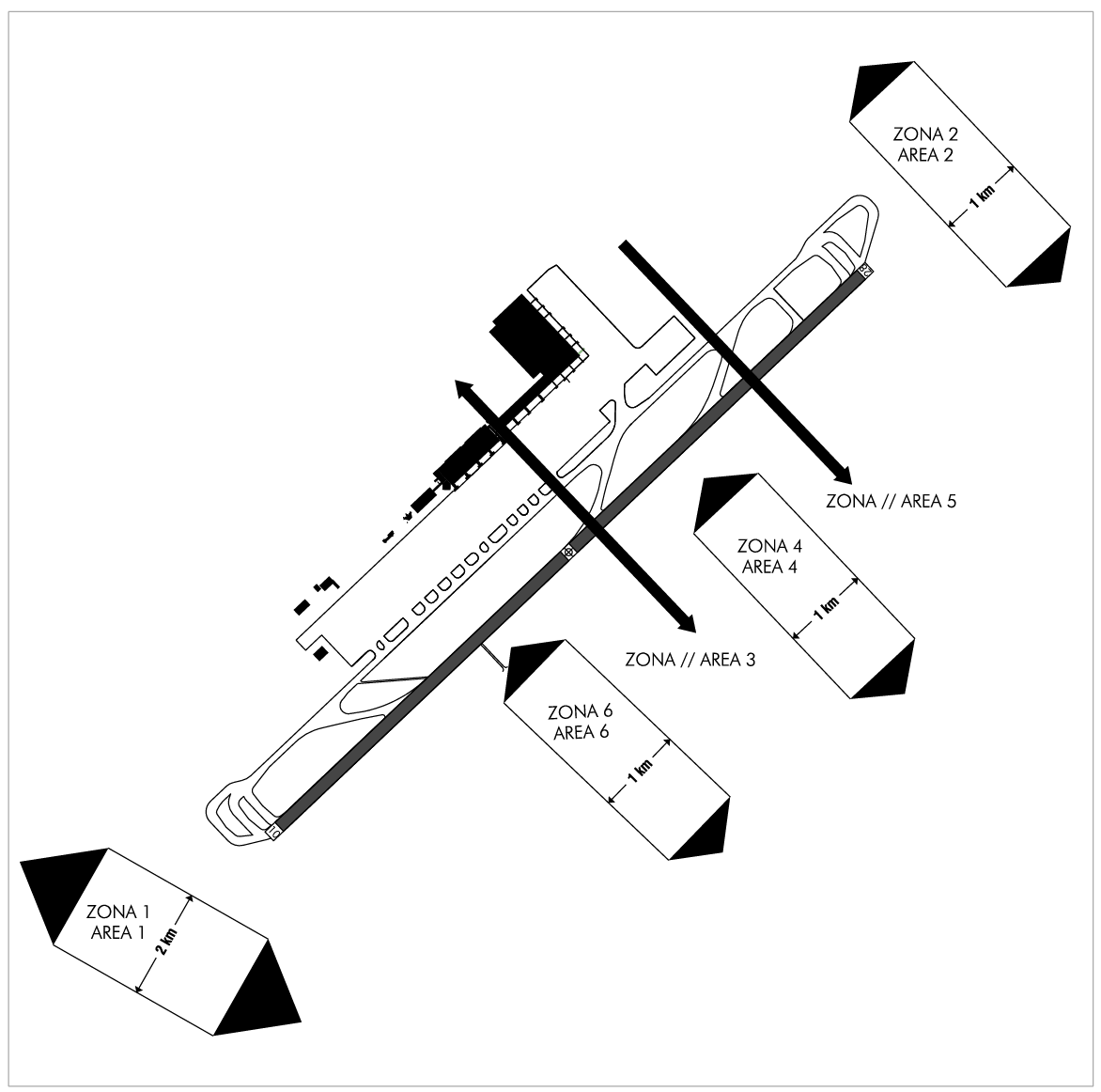
BIRD CONCENTRATION AREAS
AREA 1.- Crossing of seagulls and egrets at dawn and dusk, with a width of 2 km from THR RWY 10 in the direction of the approach to this runway.
AREA 2.- Crossing of seagulls and egrets at dawn and dusk, with a width of 1 km from THR RWY 28 in the direction of the approach to this runway.
AREA 3.- Sporadic crossing by pigeons in summer months at dawn and dusk.
AREA 4.- Night crossing of stone-curlews in lit areas.
AREA 5.- Night presence of stone-curlews in migration period (October)crossing the airfield from North to South.
AREA 6.- Presence of swallows in migration period (between August andOctober), crossing the airfield from North to South.
AERONAUTICAL CHARTS RELATED TO AN AERODROMECHARTS RELATED TO THE AERODROME
The list of charts related to the aerodrome can be found on the link below:
VISUAL SEGMENT SURFACE (VSS) PENETRATION
The instrument approach procedures affected can be found below:
IAC 1 - ILS Z RWY 10: Direct approach.
IAC 2 - ILS Y RWY 10: Direct approach.
IAC 3 - LOC Z RWY 10: Direct approach.
IAC 4 - LOC Y RWY 10: Direct approach.
IAC 5 - VOR Z RWY 10: Direct approach.
IAC 6 - VOR Y RWY 10: Direct approach.
IAC 7 - VOR Z RWY 28: Direct approach.
IAC 8 - VOR Y RWY 28: Direct approach.
IAC 9 - RNP Z RWY 28 (LPV ONLY): LPV.
IAC 10 - RNP Y RWY 28: LNAV, LNAV/VNAV.