GCLP AD 2 AERODROME DATA
AERODROME LOCATION INDICATOR AND NAME AERODROME LOCATION INDICATOR - NAME
GCLP - GRAN CANARIA
AERODROME GEOGRAPHICAL AND ADMINISTRATIVE DATA
ARP |
275555N 0152312W. See AD 2-GCLP ADC. |
|
Distance and direction from the city |
19 km S. |
|
Elevation |
24 m / 77 ft. |
|
Geoid undulation |
43.90 m ± 0.10 m. (1) |
|
Reference temperature |
28°C. |
|
Low average temperature |
18ºC. |
|
Magnetic variation |
3ºW (2025). |
|
Annual change |
9.6' E. |
|
AD administration |
CIV: Aena. MIL: Ejército del Aire y del Espacio. |
|
Address |
CIV: Aeropuerto de Gran Canaria, 35230 Las Palmas. MIL: Base Aérea de Gando. 35230 - Telde (Las Palmas). |
|
TEL |
CIV: +34-928 579 000 MIL: +34-928 328 300 |
|
FAX |
CIV: +34-928 579 117 MIL: +34-928 328 296 |
|
AFTN |
GCLP |
|
General information and specific aeronautical queries: lpaopestructura@aena.es; lpaopcpo@aena.es and lpaopsita@aena.es |
||
Approved traffic |
IFR/VFR (2). |
|
Remarks |
SITA: LPAAPYF (1) For all AD points. (2) For reasons of traffic capacity, VFR flights originating from or with destination in GCLP may not be granted authorisation during hours of high IFR traffic demand. VFR operations with arrival at/departure from Gran Canaria Airport must be coordinated by consulting the flight schedule at least 72 hours in advance via the e-mail addresses gclp_atssup@enaire.es; lpaopestructura@aena.es and lpaopcpo@aena.es, so that the feasibility of the operations may be analysed, which may not be coordinated (slot prior to flight plan) without confirmation from the airport. If the advance notice requirement is not met, permission will be denied. Except: hospital, SAR, emergency and State flights. |
OPERATIONAL HOURS
Airport |
H24 (1). |
|
Customs and Immigration |
H24. |
|
Health and Sanitation |
See GEN 1.4. |
|
AIS |
H24 (2). |
|
ARO |
H24 (3). |
|
OPV |
H24. |
|
MET briefing |
H24. |
|
ATS |
H24. |
|
Fuelling |
H24. |
|
Handling |
H24. |
|
Security |
H24. |
|
De-icing |
No. |
|
Remarks |
(1) Foreign State/military aircraft will request PPR at least 72 hours in advance, Monday to Friday from 0730 to 1400 (LT), from the AFTN address: GCLPYXYX. If this means is not available, it will be requested via FAX (+34-928 328 296), or to the e-mail: pvuelosgando@mde.es Military apron: military operations of aircraft carrying dangerous goods and arresting systems for military aircraft. See Item 20 "Local Regulations". (2) Centralised AIO Office - International NOTAM Office.
(3) Centralised ARO Office Geographical Area 15.
|
HANDLING SERVICES AND FACILITIES
Cargo facilities |
MIL: Up to 8000 kg. |
|
Fuel types |
CIV: JET A-1, AVGAS. MIL: F-34. |
|
Oil types |
No. |
|
Refuelling capacity |
CIV: Terminales Canarios:
CMD:
MIL:
|
|
De-Icing facilities |
No. |
|
Hangar space |
No. |
|
Repair facilities |
No. |
|
Remarks |
MIL: GPU: Unit of AC (up to 100 KVA) and DC (up to 2500 A). Ramp agents are authorized to perfom handling service to both commercial as well as general aviation. Ramp agents:
General Aviation:
Fuelling:
|
|
Remarks (cont) |
Handling agents for aircraft maintenance:
|
PASSENGER FACILITIES
Hotels |
No. |
|
Restaurant |
Yes. |
|
Transportation |
CIV: Buses, taxis, hire cars. MIL: No. |
|
| Medical facilities | First aid H24, 1 ambulance from 06:00 to 22:00 LT. | |
| Bank/Post Office | Banking machines/No. | |
| Tourist information | Yes. | |
| Remarks | None. |
RESCUE ANDFIREFIGHTING FIRE FIGHTING SERVICES
Fire category |
CIV: 9. MIL: 7. |
|
Rescue equipment |
In accordance with the fire category published. |
|
Removal of disabled aircraft |
CIV: Towing bars, conventional push-back, towing vehicle without bar, hydraulic jacks and compressors, for use by handling agents. The airport has specific equipment for lifting and towing ACFT available for the registered owner or operator of the ACFT affected:
MIL: Truck-mounted crane RSL-45900/A with a maximum lifting capacity of 30 TM (CRASH RECOVERY). |
|
Remarks |
Local contact details for disabled aircraft removal operation: Office CECOA (Airport coordination centre):
|
RUNWAY SURFACE CONDITION ASSESSMENT AND REPORTING, AND SNOW PLAN
Types of clearing equipment |
Not applicable. |
|
Clearance priorities |
Not applicable. |
|
Use of material for movement area surface treatment |
Not applicable. |
|
Specially prepared winter runways |
Not applicable. |
|
Remarks |
Runway surface condition assessment and reporting in accordance with the Global Reporting Format (GRF) methodology described in AD 1.2.2. Aerodrome in service during all seasons of the year. |
APRONS, TAXIWAYS AND CHECK LOCATIONS/POSITIONS DATA MOVEMENT AREA DETAILS
Apron |
Surface: CIV: Hidraulic concrete. MIL: Hidraulic concrete. Strength: CIV: South:
North: PCN 78/R/A/W/T.
MIL:
|
|
Taxiways |
Width: 23 m. Surface: Asphaltic concrete, except TWY R6, R7, R8, R9L, R9R, S1 and R18 Hydraulic concrete. Strength: CIV:
MIL:
|
|
Check locations |
Altimeter: Apron: ELEV 24 m/79 ft EXC PRKG L11, L12: 28 m/91 ft. VOR: No. INS: See AD 2-GCLP PDC. |
|
Remarks |
None. |
SURFACE MOVEMENT GUIDANCE AND CONTROL SYSTEM AND MARKINGS SURFACE MOVEMENT GUIDANCE AND CONTROL SYSTEM AND MARKINGS
Taxiing guidance system |
LGTD position indicators, NO ENTRY boards, LGTD mandatory instructions and information signs, runway holding positions, stop bars, no intrusion bars, visual guidance docking system (1), runway guard lights and stands. |
|
RWY markings |
Pre-threshold area, designators, centre line, threshold, touchdown zone, side stripe and aiming point. |
|
TWY markings |
Centre line, side stripe. |
|
Remarks |
LED lighting systems: Lights at vehicle holding position at: south of TWY Z7, north of TWY Z6, north and south of TWY Z8. Runway guard lights at: both sides of TWY R9L, R9R, S7 towards RWY 21L, S7 towards RWY 21R, R18, GATE K, S6, S5, Z1, Z2, R1, Z7, Z6 towards RWY 03R and Z6 towards RWY 03L and only on the north side of TWY R13. TWY stop bars: K, R1, R13, R18, R9L, R9R, S7, Z1, Z2, Z6 RWY 03L, Z6 RWY 03R, TWY Z7. TWY anti-intrustion bars: S1N, S1S, S2, S3, S8, Z3, Z5. (1) See AD 2-GCLP PDC. |
AERODROME OBSTACLES
Obstacles in Approach, Take-Off Climb, Conical, Inner Horizontal, Transitional, Inner Transitional and Balked Landing Surfaces established in ICAO Annex 14; and the areas 2A and 3 established in ICAO Annex 15. Those penetrating these surfaces are identified in the CSV file as "Relevante_Relevant = Si/Yes". |
See Item 10 and Data Set.s section. |
|
Remarks |
LED obstacle marker at: Mountains of Arinaga, Ámbar, Gando and Mountains of Vista Alegre Oeste THR 03R, South perimeter fencing, windsocks and apron lighting tower. |
METEOROLOGICAL INFORMATION PROVIDED METEOROLOGICAL INFORMATION
MET office |
CIV: EMAe Gran Canaria. MIL: OMD of Gando Air Base. |
|
HR |
CIV: H24. MIL: 7.5 HR (0730-1500 LT). |
|
METAR |
Half-hourly. |
|
TAF |
24 HR. |
|
TREND |
Yes. |
|
Briefing |
Aeronautical meteorological self-service: In person and by telephone. |
|
Flight documentation/Language |
Charts and plain language / Spanish. |
|
Charts |
Significant, forecasted at altitude (wind and temperature). |
|
Supplementary equipment |
Cloud, lightnings and radar information image display. |
|
ATS unit served |
TWR, APP, OPV. |
|
Additional information |
OMAe Las Palmas (GCGC); H24
EMAe Gran Canaria: H24
|
|
Remarks |
Aerodrome climatological summary available. Aerodrome warnings available. Aerodrome MET Guide available. |
RUNWAY PHYSICAL CHARACTERISTICS
RWY |
Orientation Direction |
DIM (m) |
THR PSN |
THR ELEV TDZ ELEV |
SWY (m) |
CWY (m) |
Strip (m) |
OFZ |
RESA (m) |
RWY/SWY SFC PCN |
|---|---|---|---|---|---|---|---|---|---|---|
03L (1) |
021.43°GEO 025°MAG |
3100 x 45 |
275507.94N 0152332.42W |
THR: 23.6 m / 77 ft TDZ: 23.6 m / 77 ft |
No |
No |
3220 x 280 |
No |
140 x 150 |
ASPH CONC (2) SWY: No |
21R (1) |
201.43°GEO 205°MAG |
3100 x 45 |
275641.70N 0152250.98W |
THR: 9.9 m / 32 ft TDZ: INFO NO AVBL |
No |
60 x 150 |
3220 x 280 |
No |
140 x 150 |
ASPH CONC (2) SWY: No |
03R (1) (3) |
021.42°GEO 025°MAG |
3099 x 45 |
275505.48N 0152325.25W |
THR: 21 m / 69 ft TDZ: No |
No |
No |
3219 x 280 |
No |
140 x 120 |
ASPH CONC (4) SWY: No |
21L (1) (3) |
201.43°GEO 205°MAG |
3099 x 45 |
275639.21N 0152243.84W |
THR: 8 m / 26 ft TDZ: No |
No |
60 x 150 |
3219 x 280 |
No |
140 x 150 |
ASPH CONC (4) SWY: No |
Remarks: (1) Runway designators do not correspond to the magnetic orientations. Works to change the designators are pending implementation by the airport. (2) RWY 03L/21R From THR 03L:
(3) Exemption from the regulatory requirement concerning the separation between the taxiway centre line and the runway centre line (175m): the distance between TWY R13 and TWY R18 at RWY 03R/21L is 123 m. (4) RWY 03R/21L From THR 03R:
|
||||||||||
Profile
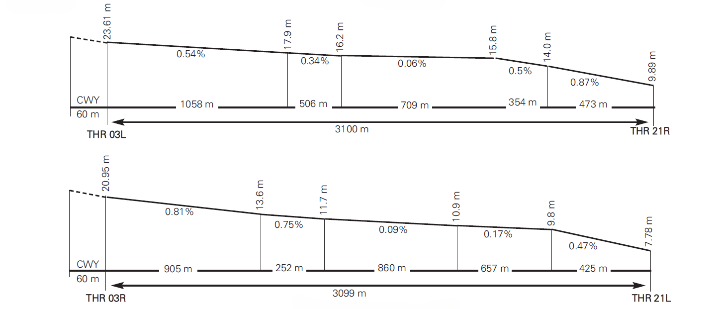
DECLARED DISTANCES
RWY |
TORA (m) |
TODA (m) |
ASDA (m) |
LDA (m) |
|---|---|---|---|---|
03L |
3100 |
3100 |
3100 |
3100 |
21R |
3100 |
3160 |
3100 |
3100 |
03R |
3099 |
3099 |
3099 |
3099 |
21L |
3099 |
3159 |
3099 |
3099 |
21L INT GCLP-02-C-B (1) |
2593 |
2653 |
2593 |
- |
Remarks: (1) GCLP-02-C-B. Bidirectional cable barrier. LOC 506 m FM THR 21L. See item 20. In the event that traffic taking off via RWY 21L requires taxiing until it crosses the runway arresting gear of said runway (GCLP-02-C-B), it shall notify ATC in the request for ATC clearance and, in any case, before commencing taxiing. |
||||
APPROACH AND RUNWAY LIGHTING
Runway |
03L |
|
Approach |
Precision CAT I, 900 m (LIH). Threshold identification lights. |
|
PAPI (MEHT) |
3º (18.40 m / 60 ft). (1) |
|
Threshold |
Green. |
|
Touchdown zone |
No. |
|
Runway centre line |
3100 m: 2500 m white+600 m yellow (LIH). Distance between lights: 15 m. |
|
Runway edge |
3100 m: 2500 m white+600 m yellow (LIH). Distance between lights: 50 m. |
|
Runway end |
Red. |
|
Stopway |
No. |
|
Remarks |
Rapid exit taxiway indicator lights (S2, S3). (1) PAPI not suitable for use by aircraft type B743, B744, B748 and A124. |
Runway |
21R |
|
Approach |
PALS CAT I 300 m. Threshold identification lights. |
|
PAPI (MEHT) |
3° (24.61 m / 81 ft). (1) |
|
Threshold |
Green. |
|
Touchdown zone |
No. |
|
Runway centre line |
3100 m: 2200 m white+600 m white and red+300 m red (LIH). Distance between lights: 15 m. |
|
Runway edge |
3100 m: 2500 m white+600 m yellow (LIH). Distance between lights: 50 m. |
|
Runway end |
Red. |
|
Stopway |
No. |
|
Remarks |
Rapid exit taxiway indicator lights (S1). (1) LED lighting. |
Runway |
03R |
|
Approach |
Precision CAT I, 900 m (LIH). Threshold identification lights. |
|
PAPI (MEHT) |
3° (20.45 m / 67 ft). |
|
Threshold |
Green. |
|
Touchdown zone |
No. |
|
Runway centre line |
3100 m: 2200 m white+600 m white and red+300 m red (LIH). Distance between lights: 15 m. |
|
Runway edge |
3100 m: 2500 m white+600 m yellow (LIH). Distance between lights: 50 m. |
|
Runway end |
Red. |
|
Stopway |
No. |
|
Remarks |
Rapid exit taxiway indicator lights (S6). |
Runway |
21L |
|
Approach |
Simple, 210 m (LIH). Threshold identification lights. |
|
PAPI (MEHT) |
3° (21.43 m / 70 ft). |
|
Threshold |
Green. |
|
Touchdown zone |
No. |
|
Runway centre line |
3100 m: 2200 m white+600 m white and red+300 m red (LIH). Distance between lights: 15 m. |
|
Runway edge |
3100 m: 2500 m white+600 m yellow (LIH). Distance between lights: 50 m. |
|
Runway end |
Red. |
|
Stopway |
No. |
|
Remarks |
Rapid exit taxiway indicator lights (S5). |
OTHER LIGHTING, SECONDARY POWER SUPPLY
ABN/IBN |
No. |
|
WDI |
1 near THR 03L, 1 near THR 21R, 1 near ARP. LGTD. |
|
TWY lighting |
Edge, R17 only in the west side. Centre line except in R13, R14, R18. |
|
Apron lighting |
Floodlighting poles. |
|
Secondary power supply |
Visual aid systems: uninterruptible power supply. Terminal building and apron lights: emergency stand-by equipment with a switch-over time of 15 seconds. |
|
Remarks |
LED lighting on apron towers (TM02-TM07) and windsocks. |
HELICOPTER LANDING AREA
Position |
|
|
Elevation |
|
|
Dimensions, surface, maximum weight, marking |
|
|
Direction |
INFO NO AVBL. |
|
Declared distances |
TODAH, RTODAH and LDAH: see item 20 for declared distances of RWY 03L/21R intersections with TWY S1 and S2; see item 13 for TODA and LDA of RWY 03L/21R, matching TODAH and LDAH. |
|
Lighting |
See item 14 for RWY 03L/21R lighting and item 15 for apron lighting. |
|
Remarks |
Air taxiing: Maximum dimensions of helicopters allowed. See AD 2-GCLP PDC 1. Apron lighting. |
Position |
TWY R15. |
|
Elevation |
INFO NO AVBL. |
|
Dimensions, surface, maximum weight, marking |
Width: 23 m, Asphaltic, concrete. PCN 21/F/A/W/T, centre line and edge. |
|
Direction |
021.42º GEO (025º MAG). |
|
Declared distances |
INFO NO AVBL. |
|
Lighting |
Edge and centre line. |
|
Remarks |
Exclusively for military helicopters under VMC. |
Position |
TWY R18. |
|
Elevation |
INFO NO AVBL. |
|
Dimensions, surface, maximum weight, marking |
Width: 23 m, Hidraulic concrete PCN 76/R/B/W/T, centre line and edge. |
|
Direction |
201.43º GEO (205º MAG). |
|
Declared distances |
INFO NO AVBL. |
|
Lighting |
Edge and centre line. |
|
Remarks |
Exclusively for military helicopters under VMC. |
Position |
GATE K. |
|
Elevation |
INFO NO AVBL. |
|
Dimensions, surface, maximum weight, marking |
INFO NO AVBL EXC PCN 52/F/A/W/T. |
|
Direction |
021.42º GEO (025º MAG) and 201.43º GEO (205º MAG). |
|
Declared distances |
INFO NO AVBL. |
|
Lighting |
Edge. |
|
Remarks |
Helicopter take-off and landing area without marking. Exclusively for military helicopters under VMC. |
AIR TRAFFIC SERVICES AIRSPACE ATS AIRSPACE
Designation |
CTR GRAN CANARIA. |
|
Lateral limits |
280938N 0152045W; 280713N 0151342W;280207N 0150554W; 274333N 0151800W; SFC ES/EN 274255N 0152610W; 274433N 0153047W; 274918N 0152850W; 275055N 0152729W; 275117N 0152831W; 280359N 0152552W; 280938N 0152045W. |
|
Vertical limits |
SFC-3100ft AMSL. |
|
Airspace class |
D. |
|
Unit Language |
GRAN CANARIA APP. |
|
Transition altitude |
1850 m/6000 ft. |
|
Hours of applicability |
- |
|
Remarks |
None. |
Designation |
CTR GRAN CANARIA ZONA A. |
|
Lateral limits |
274833.0N 0152919.9W; from this point following an arc of 2NM radius centred on 274646.7N 0153024.0W and clockwise to 274449.2N 0153051.9W; 274833.0N 0152919.9W. |
|
Vertical limits |
SFC-500 ft AGL-AMSL (3). |
|
Airspace class |
D. |
|
Unit Language |
GRAN CANARIA APP. |
|
Transition altitude |
- |
|
Hours of applicability |
- |
|
Remarks |
(3) Whichever is higher. |
Designation |
ATZ GRAN CANARIA. |
|
Lateral limits |
Circle radius 8 km centred on ARP (1). |
|
Vertical limits |
SFC-3000 ft HGT (2). |
|
Airspace class |
D. |
|
Unit Language |
GRAN CANARIA APP. |
|
Transition altitude |
- |
|
Hours of applicability |
- |
|
Remarks |
(1) Or the ground visibility, whichever is lower. (2) Or up to the cloud ceiling, whichever is lower. |
AIR TRAFFIC SERVICES COMMUNICATION FACILITIES ATS COMMUNICATION FACILITIES
Service |
Call sign |
FREQ |
HR |
Remarks |
|---|---|---|---|---|
APP |
Gran Canaria APP |
121.300 MHz |
H24 |
- |
124.300 MHz |
H24 |
- |
||
124.700 MHz |
H24 |
- |
||
363.550 MHz |
H24 |
MIL |
||
TWR |
Gran Canaria TWR |
118.300 MHz |
H24 |
- |
121.700 MHz |
H24 (1) |
GMC |
||
125.000 MHz |
(2) |
Clearance |
||
127.175 MHz |
H24 |
BACK UP |
||
121.500 MHz |
H24 |
EMERG |
||
243.000 MHz |
H24 |
EMERG |
||
257.800 MHz |
H24 |
MIL |
||
ATIS |
Gran Canaria Information |
118.600 MHz |
H24 |
|
(1) Or according to ATC or ATIS. (2) HR according to ATC or ATIS. |
||||
D-ATIS |
Gran Canaria Information |
NIL |
H24 |
Provision of ATIS information via data link not available. |
RADIO NAVIGATION AND LANDING AIDS RADIO NAVIGATION AIDS
Facility (VAR) |
ID |
FREQ |
HR |
Coordinates |
ELEV DME |
Remarks |
|---|---|---|---|---|---|---|
DVOR (3º W) |
GDV |
112.900 MHz |
H24 |
280437.5N 0152544.4W |
- |
|
DME |
GDV |
CH 76X |
H24 |
280437.6N 0152542.8W |
240 m |
DME errors and signal los from FM 160 NM at FL280. |
DVOR (3º W) |
LPC |
115.000 MHz |
H24 |
274942.7N 0152556.1W |
- |
- |
DME |
LPC |
CH 97X |
H24 |
274943.2N 0152555.9W |
60 m |
- |
LOC 21R (3º W) ILS CAT I |
RLP |
110.700 MHz |
H24 |
275457.4N 0152337.1W |
- |
205º MAG / 347 m FM THR 03L; COV 17 NM AVBL BTN 35º left & 32º right FM RCL at 2100 ft AMSL. |
GP 21R |
330.200 MHz |
H24 |
275632.1N 0152250.7W |
- |
3º; RDH 16.45 m; at 271 m FM THR 21R & 115 m FM RCL To the left in direction APCH. Full FLY-UP indications may not be received BLW GP beyond 5º left FM RCL. |
|
ILS/DME 21R |
RLP |
CH 44X |
H24 |
275632.0N 0152250.4W |
18 m |
REF DME THR 21R. |
LOC 03L (3º W) ILS CAT I |
ILP |
109.900 MHz |
H24 |
275648.8N 0152247.8W |
- |
025° MAG / 234 m FM THR 21R; COV 25 NM. COV 25 NM Not AVBL BTN ±10º from RCL BLW 4000ft AMSL. COV 17 NM Not AVBL BTN ±35º from RCL BLW 5400ft AMSL. |
GP 03L |
333.800 MHz |
H24 |
275518.5N 0152323.6W |
- |
3°; RDH 16.02 m; at 392 m FM THR 03L & 107 m FM RCL to the right in direction APCH. At 10 NM FLY-UP indications may not be received at full scalle at 1600 ft FM 7º to the left side of RCL. |
|
ILS/DME 03L |
ILP |
CH 36X |
H24 |
275518.5N 0152323.6W |
27 m |
REF DME THR 03L. |
TACAN (3ºW) |
TGN |
CH 103X |
H24 |
275524.3N 0152322.2W |
- |
- |
LOCAL AERODROME REGULATIONS LOCAL REGULATIONS
AD closed to aircraft without two-way radiocommunication.
Take-off or landing of any aircraft towing advertising posters or other objects are not allowed.
TWR contact phone numbers to be used in case of communications failure:
-
TEL: +34-928 577 143; +34-928 574 312
PREFERENTIAL RUNWAYS
North configuration shall be preferential. Other than with ATC clearance, operations shall be carried out on the basis of the following allocation:
- North configuration:
- Arrivals: RWY 03L
- Departures: RWY 03R
- South configuration:
- Arrivals: RWY 21R
- Departures: RWY 21L
The described use of runways involves a possible invasion of the ILS critical area, so signal fluctuations may be observed on final approach.
Pilots asking for the use of a runway different from the one described, must do so on requesting start-up and shall be responsible for the possible delays.
MINIMUM RUNWAY OCCUPANCY TIME
ARRIVAL
To minimise the runway occupancy time and the possibility of "go-around", pilots are reminded:
-
To vacate the runway rapidly and at the highest possible speed without prejudice to safety.
-
To adjust taxi speed after touchdown when it is evident that the aircraft will miss the planned RET, avoiding low speeds on the runway.
-
To vacate the runway completely before halting. Should they not be able to contact GMC, after leaving the runway free, they should hold until they establish that communication.
-
Report runway vacated on the LCL/TWR frequency before changing to the GMC frequency.
Arrivals to RWY 03R
In the event that an aircraft that has landed on RWY 03R cannot taxi over the cable, they must inform ATC as soon as possible, and where necessary they will be instructed to:
- Vacate RWY 03R via TWY S6-S3 if it is available.
- Vacate RWY 03R via TWY S8 or GATE K to proceed via TWY R18, and await ATC clearance to cross the runways and proceed via TWY R9-R8.
DEPARTURES
Pilots should be ready for departure when reaching the runway-holding position.
On receipt of line-up clearance pilots should ensure that they are able to taxi and line-up on the runway as soon as the preceding aircraft has commenced either its take-off roll or, in the case of an arrival, it has passed their location at the holding position.
Pilots who require additional separations (due to wake turbulence or other reason), shall notify ATC as soon as possible and before entering the runway.
Pilots should be able to commence the take-off roll immediately when takeoff Clearance is issued. Pilots unable to comply with this requirement shall notify ATC as soon as possible, in any case, before entering the runway, and await instructions. When appropriate, ATC could cancel the clearance and instruct the aircraft to vacate runway.
Departures from RWY 21L
In the case that an aircraft that is to take off from RWY 21L requires to taxi beyond the fixed braking cable on that runway (GCLP-02-C-B), it shall notify ATC in the request for ATC clearance and, in any case, before commencing taxiing.
The position of the fixed braking cable on RWY 21L (GCLP-02-C-B) and the declared distance for operation from that point are stated in items 20 and 13, respectively.
STANDARD TAXIING PROCEDURES
START-UP
- ATC will issue aircraft start-up clearances and aircraft push-back and taxi instructions. It will also issue taxiing instructions to aircraft entering and leaving the apron. Its tasks will include managing the process of engine start-up, push-back, towing and/or taxiing of aircraft, following the scheduled take-off times. In this way, it will organise the sequence of push-back/taxiing together with the arrival traffic on the apron, to achieve a safe, organised and optimal sequence upon request by the crews.
- Aircraft must be fully ready to start-up before submitting the request via DCL or calling on the appropriate frequency: CLR (125.000 MHz), GMC (121.700 MHz) or LCL/TWR (118.300 MHz). When CLR frequency is in service or frequencies are unified into TWR it shall be reported by ATIS.
- Aircraft should be ready for start-up no later than their estimated off-block time (EOBT).
- Pilots will contact GRAN CANARIA RODADURA (GMC 121.700 MHz) to request permission to start-up. On requesting start-up clearance, pilots shall report to ATC the complete call sign, aircraft type and series, stand occupied and the ATIS message received.
- In case of aircraft with 52 m or longer wingspan, pilot shall report it is a code letter aircraft E/F as appropriate.
- Pilots or aircraft operators who consider that their take-off run may be less than 300 m should notify ATC as soon as possible and should do so in any case before accessing the runway in service.
- Start-up clearance shall be issued as soon as requested, unless delays are expected to exceed 15 minutes, in which case ATC shall provide the appropriate engine start-up time.
- Usually, once engine start-up clearance or expected time has been provided, GRAN CANARIA TWR will issue the corresponding ATC clearance.
- In the start-up engines and simultaneous push-back with autonomous APU manoeuvre, aircraft shall maintain the idle regime until being lined-up with the apron taxiway.
- In the start-up engine manoeuvre with GPU at stands with boarding bridges and/or cross-bleed start in the taxiway, prior CECOA approval is required. Aircraft, subject to coordination and approval by CECOA, shall ensure that the boarding bridge is disconnected and that no passengers board or disembark on foot at stands T01 or N12 (M04 and N11 respectively). Unless otherwise advised by TWR, they shall start-up the engine located on the opposite side of the boarding bridge, shall accomplish the push-back manoeuvre maintaining the idle regime, and once lined-up with the apron taxiway, they will may increase the power to start-up the rest of engines. In this final case, the pilot shall inform TWR of their intention to perform cross-bleed start, increasing engine power in the taxiway before starting push-back.
- Taxiing after autonomous start-up from PRKG P00 to P58 shall be performed aligned with the centre line of the parking stand and the turn shall be performed following the markings to avoid jet blast affecting equipment and aircraft that may be parked in adjacent stands.
REQUEST FOR ATC CLEARANCE AND START-UP VIA DATALINK
Departure procedures via DCL are applied at Gran Canaria Airport for ATC clearance and start-up services. For more information on the DCL service, see AIP ENR 1.5, Section 3. DEPARTING FLIGHTS, ATC clearance and startup via datalink. In the event of discrepancies, voice communication shall prevail over the datalink.
The pilot may request ATC clearance via DCL up to 30 minutes prior to the EOBT.
-
The pilot shall request ATC clearance and start-up jointly via RCD. The RCD message must contain the following information:
- Aircraft call sign according to flight plan filed (FPL).
- Aerodrome of origin.
- Parking position.
- Destination aerodrome.
- Letter corresponding to ATIS information received.
- ICAO designator of aircraft type.
Free text included in the RCD by the pilot shall not be considered by the ATC. Special requirements must always be communicated by voice.
-
The pilot will receive an acceptance message "RCD RECEIVED" or a cancellation message "RCD REJECTED".
-
If accepted, the ATC will transmit a CLD message with the following fields:
-
Aircraft call sign.
-
Destination aerodrome.
-
Runway assigned for departure.
-
Departure procedure (SID). Note: The initial altitude shall correspond to the published SID.
-
Mode A SSR code (SQUAWK).
-
ADT (Approved Departure Time). Note: ADT=CTOT of flight, if available.
-
Next frequency.
-
Letter of the valid ATIS information.
-
Additional information, including the start-up clearance or instructions to request said clearance in the event that the start-up clearance parameters are not fulfilled according to the EOBT.
-
-
When an RCD message is sent within the valid EOBT range, ATC and startup clearance will be given. If not ready for start-up, the pilot shall not accept the clearance and shall contact the air controller by voice when ready.
-
When an FSM message "REVERT TO VOICE PROCEDURES" is received, the datalink communication shall be terminated and the switch to voice procedure shall apply.
- When the CLD message is received, the pilot shall act as follows:
- If any inconsistency in the received message is detected, the pilot will switch to voice to request a new clearance.
- If the CLD message clearance is deemed correct, the pilot will respond via datalink with a CDA message (Departure Clearance Echoback).
-
If the ATC system does not receive a CDA message within the holding time, or a CDA inconsistent with the previous CLD message is received, the datalink communication will be terminated and a "CDA REJECTED" message will be received on the FMS.
-
When a successful CDA message is received, the ATC system will transmit a "CLEARANCE CONFIRMED" message on the FMS to the aircraft and terminate the datalink communication.
EXCHANGE OF DATA WITH NMOC – ADVANCED ATC TWR
The airport of Gran Canaria exchanges information for departure flights by applying the Advanced ATC TWR procedures. Message exchanges from the local system to the ATM network uses the European standard for A-CDM airports, using the following message types:
-
A-DPI for all instrumental departure flights.
-
C-DPI when required.
When start-up approval has been announced and the aircraft starts to exit the stand, the target take-off time (TTOT) is calculated and transmitted to NMOC (Network Manager Operations Center) via an ADPI message. The use of the actual off-block time (AOBT) instead of the EOBT of the flight plan, along with the variable taxiing time, increases the precision of the take-off time. After reception of the A-DPI, DLA or CHG messages that change the flight plan data shall not be accepted. If regulated, the CTOT assigned before receiving the A-DPI shall be maintained.
If an aircraft has to abort taxiing for technical reasons, the airport shall send a C-DPI message to the NMOC (cancellation message of departure flight planning information). The result of the C-DPI is that the flight plan shall be suspended by informing the operator via an FLS message with the comment "Suspended by Departure airport". The flight plan can be activated again by updating the EOBT with a DLA or CHG message.
GROUND MOVEMENT
Avoidance of collisions with other aircraft or obstacles is the responsibility of:
-
Pilots, when taxiing on the apron and in the zones not visible from TWR.
- Ground handling companies, during the push-back manoeuvre and/or exit from the stand.
- All surface movements of aircraft, towed aircraft, personnel and vehicles on the manoeuvring area are subject to ATC clearance.
- GMC is responsible for:
- The control of every aircraft, personnel, and vehicles movement on the manoeuvring area except for the runway or runways is use.
- To issue clearances and instructions for towed push-back and taxiing of aircraft.
- Use of stop bars:
The airport of Gran Canaria has stop bars on the access-to-runway taxiways Z1, Z2, R1, Z7, R13; R9L; R9R; R18, as well as on the taxiway S7 in the direction RWY 03L/21R towards RWY 03R/21L, of manual switch-off and automatic switch-on.
The use of stop bars is associated to:
- Runway crossing and occupancy: In cases of runway closures for inspection or similar activities, or works.
- As a result of deterioration in the weather conditions and, in any case, in Phase I (Warning) of the PPOAM (see item 22).
Push-back manoeuvring and taxiing
- Aircraft must be ready for taxiing within the next 5 minutes to the approved start-up time (with or without push-back). In the case of carriers operating aircraft that require more time, ATC should be informed in advance.
- In all stands with autonomous exit, the exit manoeuvre shall be carried out at the minimum regime to initiate taxiing.
- All aircraft shall observe ATC instructions to reach the runway-holding position or runways in use.
- Aircraft shall report ATC vacating runway, and will be informed of their expected stand and any further instruction, if required to reach the stand.
- ATC clearances and instructions must be completely read-back.
- As a general rule, push-back manoeuvres at stands T (except T12 and T13 in north configuration) shall be performed facing the runway in use. If a push-back in the opposite direction is required, TWR shall be informed when requesting IFR ATC clearance. This non-standard manoeuvre may involve delays exceeding 15 minutes.
Powerback operations
Powerback operations require prior authorization of the Aerodrome Management and will be executed under the sole responsibility of the aircraft operator. The company agent must request this operation well in advance to the Aerodrome Management.
This type of operation is only allowed for:
-
Turboprop aircraft smaller than or equal to AT72 dimensions in the PRKG M (M01, M02, M03 and M04).
-
Turboprop aircraft larger than AT72 dimensions, the company agent must request well in advance the feasibility of this operation to e-mail: lpaopestructura@aena.es
The airport shall analyze the safety of the operation and the noise pollution caused by it.
Push and hold manoeuvring
When an aircraft is completely ready to operate (start-up) before the allocated slot, the pilot may request a "Push and Hold" to ATC. If appropriate, equipment for push-back will tow the aircraft out of PRKG T (Tango), and once in the taxiway, marshaller will guide it to a remote parking position with autonomous exit, so that if the company is granted an improved SLOT (REA), it may exit the stand and in this way shorten the time to get to the threshold.
When the aircraft requests "Push and Hold", the CECOA, subject to availability, will assign an intermediate stand in a remote position prior to its final exit.
Possible remote stand to perform this manoeuvre are:
-
With RWY 03L/R in service: From P36 to P56.
-
With RWY 21L/R in service: From P00 to P24.
Access to stands manoeuvring
Access to stands from taxiways may require oversteer manoeuvres.
AIRCRAFT STANDS CHARACTERISTICS
See AD 2-GCLP PDC.
RESTRICTIONS TO STANDS
- The use of 400 Hz facilities is mandatory at every stand where this service is available.
- The use of the aircraft Auxiliary Power Unit (APU) is forbidden in all stands where the 400 Hz / air-conditioning service is available, from 2 minutes after on-block to 5 minutes before off-block.
- Aircraft APU may only be used when the 400 Hz current supply facilities or mobile units are non-operational, or when the air-conditioning service is required and the equipment is not available.
- Aircraft operating at autonomous stands shall do it at the minimum regime required.
- During the winter season:
- No new overnight stays requested as from 1 October are authorized for arrivals between 10:00 and 19:00 UTC, for both general aviation and commercial flights (Friday–Saturday and Saturday–Sunday nights).
- Aircraft are not permitted to remain on the apron on Saturdays and Sundays between 10:00 and 19:00 UTC for stopovers exceeding 4 hours or for periods longer than one day when apron capacity is affected, for both general aviation and commercial flights.
TAXIING RESTRICTIONS
- Runway in use 03
The following restrictions due to turning radius exist on taxiways:
- The turn from TWY S2 to TWY R6 may be made by code letter C or lower aircraft.
- The turn from TWY R10 by GATE J to TWY R2 may not be made by aircraft as B777, A350 and A340.
- The turn from TWY S3 to TWY R7 may be made by code letter C or lower aircraft.
The following restrictions due to aircraft dimensions exist on taxiways:
- TWY Z1 shall serve to give access to RWY 03L from TWY R3 for code letter D or lower aircraft.
- There exist restrictions on the simultaneous use of the following taxiways:
Aircraft code letter holding at TWY Z1 |
MAX ACFT allowed to taxi from TWY R3 to TWY R2 |
|---|---|
A (LJ55; C421) (MAX wingspan 14.57 m) |
ALL (MAX wingspan 64.40 m) |
B (CRJ2; E145; SW4) (MAX wingspan 23.72 m) |
ALL (MAX wingspan 64.40 m) |
C (B738; A321; AT72) (MAX wingspan 35.80 m) |
ALL (MAX wingspan 64.40 m) |
D (B753; B763; C130) (MAX wingspan 51.90 m) |
ALL (MAX wingspan 64.40 m) |
(1) Code letter F aircraft shall follow their own procedure. |
|
Aircraft code letter holding at TWY Z2 |
MAX ACFT allowed to taxi from TWY R2 to TWY R1 |
|---|---|
A (LJ55; C421) (MAX wingspan 14.57 m) |
ALL (MAX wingspan 64.40 m) |
B (CRJ2; E145; SW4) (MAX wingspan 23.72 m) |
ALL (MAX wingspan 64.40 m) |
C (B738; A321; AT72) (MAX wingspan 35.80 m) |
ALL (MAX wingspan 64.40 m) |
D (B753; B763; C130) (MAX wingspan 51.90 m) |
D (B753; B763; C130) (MAX wingspan 51.90 m) |
E (1) (A330; A340; B744) (MAX wingspan 64.40 m) |
C (B738; A321; AT72) (MAX wingspan 35.80 m) |
(1) Code letter F aircraft shall follow their own procedure. |
|
- Hoding position on TWY S6: if there is an aircraft at TWY S6 holding short of RWY 03L/21R, ATC shall consider RWY 03R/21L occupied.
- A form of coordination is established between the taxiways from TWY R13 up to TWY R18 and RWY 03R/21L during the operation of code letter E aircraft, in such a way as to ensure there are no simultaneous operations on the runway and taxiways by the code letter E aircraft and code letter C or higher aircraft.
- Runway in use 21
- The turn from TWY R2 by GATE J to TWY R10 may not be made by aircraft as B777, A350 and A340.
- TWY Z1 may be used by code letter D or lower aircraft to vacate RWY 21R.
- Incompatibilities of TWY R9R with TWY R8 and R9L:
Aircraft code letter holding at at TWY R9R
MAX ACFT taxiing from TWY R8 to TWY R9L
A (LJ55; C421)
(MAX wingspan 14.57 m)
ALL
(MAX wingspan 64.40 m)
B (CRJ2; E145; SW4)
(MAX wingspan 23.72 m)
ALL
(MAX wingspan 64.40 m)
C (B738; A321; AT72)
(MAX wingspan 35.80 m)
D (B753; B763; C130)
(MAX wingspan 51.90 m)
D (B753; B763; C130)
(MAX wingspan 51.90 m)
C (B738; A321)
(MAX wingspan 35.80 m)
E (1) (A330; A340; B744)
(MAX wingspan 64.40 m)
A (LJ55; C421)
(MAX wingspan 14.57 m)
(1) Code letter F aircraft shall follow their own procedure.
- In order to prevent these incompatibilities, code letter D or E aircraft (B752 or bigger) shall usually be cleared to RWY 21 holding position at "ROMEO 9 LIMA".
- Caution when accessing R9L with aircraft on R9R.
- Holding position on TWY S7: If there is an aircraft at TWY S7 holding short of RWY 21L/03R, ATC shall consider RWY 21R/03L occupied.
- Holding position on TWY S7: If there is an aircraft at TWY S5 holding short of RWY 21R/03L, ATC shall consider RWY 21L/03R occupied.
TAXIING ROUTES
The main transfer points between the manoeuvring area and the apron coincide with the entry/exit gates of the apron.
There is no transfer of aircraft between air traffic services and apron services, as far as communications are concerned.
Once the aircraft arrives at one of the transfer points, the "FOLLOW ME" vehicle begins to guide it along the axis of the corresponding taxiway on the apron, keeping its distance from the rest of the aircraft and vehicles. If it detects any unauthorised manoeuvre, it will stop the vehicle, signalling the guided aircraft to stop.
Preferably, the apron entry and exit gates will be as follows:
-
NORTH configuration RWY 03: exit via GATE E and J (EXC aircraft as B777, A350 and A340), entry via GATE F and G
-
SOUTH configuration RWY 21: exit via GATE F and G, entry via GATE J (EXC aircraft as B777, A350 and A340), E and F.
Unless ATC advises differently, aircraft shall taxi following the standard taxiing routes defined hereafter.
Aircraft going to stand without signalman guidance must hold short of this point in all cases, and wait for the arrival of a marshaller in order to ensure the proper and safe aircraft parking.
NORTH CONFIGURATION RWY 03
Arrivals:
Additionally, in the case of aircraft which have been cleared to land on RWY 03R:
-
They shall vacate RWY 03R, whenever possible, via TWY S6 and, if they do not receive express clearance from ATC, they shall hold short of RWY 03L/21R at runway-holding position TWY S6. Once cleared on the LCL/TWR frequency (118.300 MHz), they shall cross RWY 03L/21R and vacate via TWY S3, following from that moment the routeings defined for RWY 03L.
-
If the aircraft vacates runway RWY 03R at the end, it shall hold short of runway RWY 21L at runway-holding position on TWY S7 and, after express clearance from ATC on the LCL/TWR frequency (118.300 MHz), it shall proceed via TWY S7 to cross RWY 03L/21R and continue via TWY R9R/L and R8 along the routeing defined for RWY 03L.
| ARRIVALS RWY 03L - CODE LETTER C or LOWER AIRCRAFT (1) | ||
|---|---|---|
To
|
From | |
| S3/R8 | S2 | |
P00-P26 |
R7 |
R7 |
P28-P52 |
R7-R4 |
R6-R4 |
P54-P66, L02, L04, L06, L08 |
R7-R3 |
R6-R3 |
L01, L03, L05, L07, L09-L12 |
R7, GATE F, R11-R10 |
GATE F, R11-R10 |
T01-T11 |
GATE G, R12 |
R7, GATE G, R12 |
T12-T21 |
R7, GATE F, R11 |
GATE F, R11 |
T21B-T23 |
R7, GATE F, R11-R10 |
GATE F, R11-R10 |
| ARRIVALS RWY 03L - CODE LETTER D or GREATER AIRCRAFT (1) | |||
|---|---|---|---|
| From | |||
To
|
R8 | S3 | S2 |
P00-P26 |
R7 |
GATE G-R12-GATE F-R7 |
R7 |
P28-P52 |
R7-R4 |
GATE G-R12-GATE F-R4 |
GATE F-R11-GATE E-R4 |
P54-P66 |
R7-R3 |
GATE G-R12-GATE F/GATE E-R3 |
GATE F-R11-GATE E-R3 |
T01-T11 |
GATE G, R12 |
GATE G-R12 |
R7, GATE G, R12 |
T12-T21 |
R7, GATE F, R11 |
GATE G, R12-R11 |
GATE F, R11 |
T21B-T23 |
R7, GATE F, R11-R10 |
GATE G-R12-R11-R10 |
GATE F, R11-R10 |
(1) See section 5, TAXIING RESTRICTIONS, TWY S3-R7 and TWY S2-R6 turning restrictions. |
|||
Departures:
| DEPARTURES NORTH CONFIGURATION (RWY 03L or 03R) | |
|---|---|
From |
To |
| R1, Z2 | |
N01, N11, N12, N02, N03 |
R12-R11, GATE E, R3-R2 |
T01-T11 |
R12-R11, GATE E, R3-R2 |
T12/T12A-T14 |
R11, GATE F (1), R6-R2 |
T15-T23 |
R11, GATE F (1), R6-R2 |
P54-P66 |
R10, GATE J, R2 (exit to Z2 via GATE E). |
L02, L04, L06, L08 |
R3-R2 |
(1) Caution: Do not enter TWY S2 when instructed to taxi via GATE F. (2) RWY 03L accessible only via TWY Z2. |
|
SOUTH CONFIGURATION RWY 21
Arrivals:
| ARRIVALS RWY 21R | |||
|---|---|---|---|
To |
From | ||
| R2 | S1 | S1N | |
P00-P26 |
R3-R7 |
R4, GATE E, R11, GATE F, R7 |
R6-R7 |
P28-P40 |
R3-R6 |
R4, GATE E, R11, GATE F, R6 |
R6 |
P42-P44 |
R3-R4 |
R4, GATE E, R11, GATE F, R6-R4 |
R6, GATE F, R11, GATE E, R4 |
P46-P52 |
R3-R4 |
R4 |
R6, GATE F, R11, GATE E, R4 |
P54-P66 |
R3 |
R4-R3 |
R6, GATE F, R11, GATE E, R3 |
L01, L03, L05, L07, L09-L12 |
GATE J, R10 |
R4, GATE E, R10 |
R6, GATE F, R11-R10 |
L02, L04, L06, L08 |
R3 |
R4-R3 |
R6, GATE F, R11, GATE E, R3 |
T01-T12A |
R3, GATE E, R11-R12 |
R4, GATE E, R10-R12 |
R6, GATE F, R12 |
T13-T21 |
R3, GATE E, R11 |
R4, GATE E, R11 |
R6, GATE F, R11 |
T21B-T23 |
R3, GATE E, R10 |
R4, GATE E, R10 |
R6, GATE F, R11-R10 |
Additionally, in the case of aircraft which have been cleared to land on RWY 21L:
- They shall vacate the runway at the end, hold short of RWY 03L at runway-holding position on TWY Z7 and, after express clearance from ATC on the LCL/TWR frequency (118.300 MHz), they shall proceed via TWY Z7/Z4 and continue via TWY R1 along the routeings defined for RWY 21R.
Departures:
| DEPARTURES SOUTH CONFIGURATION (RWY 21R or 21L) | |
|---|---|
From |
To |
| R9R / R9L | |
N01, N11, N12, N02, N03 |
R12, GATE G (1), R8 |
P00-P26 |
R12, GATE G (1), R8 |
T12-T23 |
R10-R11, GATE F (2), R7-R8 |
L02, L04, L06, L08 |
R3-R8 |
(1) Caution: Do not enter TWY S3 when instructed to taxi via GATE G. (2) Caution: Do not enter TWY S2 when instructed to taxi via GATE F. |
|
OPERATION OF HELICOPTERS
Military Helicopters:
The take-off/landing zones for the operation of military helicopters shall be, in accordance with the provisions of item 16:
- GATE K.
- TWY R15.
- TWY R18.
Military helicopters proceeding in emergency shall perform the approach to runway, except:
- When the emergency occurs during final approach to TWY R15 or TWY R18, in which case they shall finish the manoeuvre.
- When loss of manoeuvrability or performance does not allow to perform it in the runway.
Civil helicopters:
Helicopters can operate in a 24H schedule.
The stands for this type of aircraft are in the south-west zone of the civil apron.
There is one stand without turning manoeuvre for helicopters of a maximum of S61-SIKORSKY S-61N (LH02), and two stands without turning manoeuvre for a maximun helicopters type A139-AGUSTAWESTLAND AW139 (LH01 and LH03) and one stands with turning manoeuvre for a maximun helicopter type S61-SIKORSKY S-61N (LH04) (see AD 2-GCLP PDC).
- Helicopters will be instructed to land or take-off from the FATO defined on RWY 03L/21R. The following possible landing/take-off points for helicopters on the runway are defined below:
- THR (03L in north configuration or 21R in south configuration).
- Proximities of the ARP.
- Helicopters operating under a letter of exemptions (operational flights on missions such as attending emergencies) or others as required due to special circumstances (wind intensity greater than 20 kt) in performance 1, based on GCLP, and which are type SK61 or smaller and with prior coordination with ATC, may operate in the FATO E or FATO J.
Helicopters shall receive weather information in a first communication from ATC, and according to said information shall coordinate with ATC the FATO in which they are required to operate.
Declared distances, considered exclusively for operating helicopters:
RWY |
RTODAH (m) |
TODAH (m) |
LDAH (m) |
|---|---|---|---|
03L INT S1 (ARP) |
1550 |
1550 |
1550 |
21R INT S2 (ARP) |
1550 |
1550 |
1550 |
The following procedures shall generally be applied:
NORTH CONFIGURATION (RWY 03L):
DEPARTURES:
Departing helicopters will be authorised by ATC to taxi from the stand to TWY R10 and exit the apron via the following routes, which will be determined by ATC and operators based on wind conditions:
-
GATE J, taxi via TWY R2 to the holding point on TWY Z2, awaiting ATC instruction to enter RWY 03L/21R for take-off on RWY 03L.
-
GATE E, awaiting ATC instructions to taxi via R4 to the holding point on TWY R9R/R9L, then awaiting ATC instruction to enter RWY 03L/21R for take-off on RWY 03L. This route shall only be used when wind conditions preclude the taxiing procedure established in the previous item.
ARRIVALS:
Arriving helicopters shall comply with the following procedures:
-
Land on RWY 03L, vacate the runway via exit TWY Z2-R2 and be authorised by ATC to enter the apron via GATE J, following FOLLOW ME vehicle guidance via R10 to the stand.
-
Land at the ARP, vacate via S2 and be authorised by ATC to enter the apron via GATE F, following FOLLOW ME vehicle guidance via R10 to the stand.
SOUTH CONFIGURATION (RWY 21R):
DEPARTURES:
Departing helicopters will be authorised by ATC to taxi from the stand to TWY R10 and exit the apron via the following routes, which will be determined by ATC and operators based on wind conditions:
-
GATE E, taxi via TWY R4-R6-R7-R8 to the holding point on TWY R9R/R9L, awaiting ATC instructions to enter RWY 03R/21R for takeoff on RWY 21R.
-
GATE J, awaiting ATC instructions to taxi via TWY R2-Z2 to the holding point on TWY Z2, then awaiting ATC instructions to enter RWY 03L/21R for take-off on RWY 21L. This route shall only be used when wind conditions preclude the taxiing procedure established in the previous item.
ARRIVALS:
Arriving helicopters shall carry out the following procedures:
-
Land normally at the ARP, vacate the runway via TWY S1-R4 and be authorised by ATC to enter the apron via GATE E, following FOLLOW ME vehicle guidance via TWY R10 to the stand.
-
Landing on RWY 21R threshold, once authorised by ATC, the helicopter shall vacate RWY 03R/21L via TWY R9R/R9L, continuing taxiing via TWY R8-R7-R6-R4 to enter the apron via GATE E. From this point, follow FOLLOW ME vehicle guidance via TWY R11-R10 to the stand.
OPERATION OF CODE LETTER F AIRCRAFT
The procedure described below is valid for occasional operations of the following code letter F aircraft: A124, B748 and A380. The operation of aircraft of a length and/or wingspan greater than the one indicated (e.g. A225) requires specific prior analysis.
The arrival or stop over of code letter F aircraft is not authorised if it has not received prior authorisation by the Airport Management.
Two operations whith aircraft with a code letter F will not be authorized while simultaneously staying at the airport for part or all of the stopover time.
In the event of an unexpected operation for this type of aircraft (e.g. emergencies), the appropriate measures shall be taken and coordinated in line with this procedure.
- Runways: Code letter F aircraft shall preferably operate on RWY 03L/21R. If necessary, they can operate on RWY 03R/21L.
- Parking: Exit of the aircraft included in this procedure from the aircraft stand shall be carried out using push-back, nosing as per ATC instructions.
A124 and B748
The preferred aircraft stand is T21B, leaving PRKG LH01, T21, T22 and T23 out of service (free without parked aircraft).
Another aircraft stand is available with a capacity for aircraft with a wingspan over 65 m, T20, leaving PRKG T19, T21 and T21B out of service.
A124 – B748 |
|||
|---|---|---|---|
| Runway in use |
ARR / DEP |
Taxi route |
PRKG |
03L (preferred) |
ARR |
Vacate at end of runway, TWY R9R, R8 …, GATE E. |
T21B or T20 |
DEP |
TWY R10, GATE E, TWY R4, R3, R2, Z2. |
||
21R (preferred) |
ARR |
Vacate at end of runway, TWY Z3, R1, (alternative Z2), R2-R4, GATE E and TWY R10. |
|
DEP |
TWY R10, GATE E, TWY R6-R8 & R9R. |
||
03R |
ARR |
Vacate at end of runway, TWY S7, R9R, R8-R6, GATE E and TWY R10. |
|
DEP |
TWY R10, GATE E, TWY R4-R2, R1, Z4 & Z7. |
||
21L |
ARR |
Vacate at end of runway, (Z7, Z4, R1), R2-R4, GATE E and TWY R10. |
|
DEP |
TWY R10, GATE E, TWY R6-R8, R9R & S7. |
||
A380
This aircraft shall park in PRKG N02, leaving PRKG M01, M02, M03, M04, N11, N12, N01, N03 and P00, P02, P04 out of service (free without parked aircraft).
- Taxiing: aircraft shall always be accompanied by a "FOLLOW ME" vehicle, which shall go with the aircraft from the aircraft stand to the runway-holding positions, as well as from the runway-holding positions, after vacating it, to the stand on arrival.
The permitted taxi routes according to the type of aircraft are:
| A380 | |||
|---|---|---|---|
Runway in use |
ARR / DEP |
Taxi route |
PRKG |
03L |
ARR |
Vacate at end of runway, TWY R9R, R8 and GATE G. |
N02 |
DEP |
GATE G, TWY R8, R9R, S7, back-track via RWY 03R/21L and TWY Z7-TWY Z5 up to RWY 03L. |
||
21R |
ARR |
Vacate at end of runway, TWY Z5, Z7, back-track via RWY 21L/03R, TWY S6, RWY 21R/03L crossing, TWY S3 and GATE G, or by end of the runway. |
|
DEP |
GATE G, TWY R8 & R9R. |
||
03R |
ARR |
Vacate at end of runway, TWY S7, R9R, R8 and GATE G. |
|
DEP |
GATE G, TWY R8, R9R, back-track via RWY 03L/21R and by TWY Z5, Z7. |
||
21L |
ARR |
Vacate at end of runway, TWY Z7-TWY Z5. |
|
DEP |
GATE G, TWY R8, R9R & S7. |
||
Operational and Taxiing Restrictions:
- Under no circumstances, a code letter F aircacft will vacate runway via rapid exit taxiway when landing, it may only vacate the runway via its ends only (TWY R1, Z2 or R9R).
- The use of PAPI signals is not recommended, to prevent incorrect instructions during landing.
- During taxiing, if the code letter F aircraft is a four-engined model, it shall keep the outer engines idling to prevent the intake of FOD.
- Oversteering manoeuvres are required to correct the path on some curved sections of the taxiway.
- A124 and B748: apron access/exit via GATE E.
- A388: apron access/exit via GATE G.
- After the operation (landing, take-off, taxiing) of a code letter F aircraft, the taxiing route and runway shall be inspected.
OPERATIONAL SAFETY REPORTS
Pilots/operator shall report to the airport as soon as possible about any accidents, incidents, occurrences or events which may have a potential operational impact and in which they have been involved or witnessed. The aim of these reports is the compilation of the information in order to improve operational safety, independently of the compulsory report of the occurrence to the appropriate aeronautical authority.
Data may be sent in any format, including at least the following information:
- Date and time.
- Site.
- Parties involved (data used to identify vehicles, aircraft ... involved).
- Companies implicated.
- Description of the facts.
- Any other data considered relevant (e.g. lighting conditions, weather, phase of the operation such as takeoff / landing / stopover, pavement conditions...).
Contact e-mail address of the airport, for the reception of operational safety reports, is the following: Seguridad_Operacional_LPA@aena.es
In addition to notifying the airport by means of the indicated system, it is necessary to send at least basic data of the accident, incident, occurrence or event to the air traffic control service provider (ATC).
On the specific instance of safety reports related with the air traffic control service provider (manoeuvring area, flight phases and ATS airspace) these may be sent to the e-mail address: canariassafetymanagement@enaire.es
USE OF ENGLISH LANGUAGE IN RADIO COMMUNICATIONS
Whenever there is a pilot on the frequency/frequencies in use in the manoeuvring area who does not speak Spanish, the use of English in groundair communications between aircraft and the ATS unit shall be mandatory; without prejudice to the application of the provisions in SERA.2010 under 'Responsibilities of the pilot in command', and the decisions which may be taken by the pilot in command in such circumstances, and likewise in the emergency situations which could arise on board the aircraft, and in the adoption by the air traffic contoller of the measures it may deem necessary to maintain safety.
This is applicable, as appropriate, in the operational scenarios described in Annex IV to the Real Decreto 1180/2018:
-
The following operations of landing and take-off:
-
Clearances to land with traffic in the holding position.
-
Clearances to take off with traffic on final approach.
-
Clearances to enter and line up from congested holding positions.
-
-
Operations in which there are aircraft entering the active runway, but which are neither going to land or to take off. Typically, these operations are taxiing along the active runway or crossing the active runway.
In the foregoing operational scenarios, Spanish may be used in ground-air communications between the aerodrome traffic control units and flights operating under visual flight rules (VFR), always provided that the pilots do not possess appropriate English language proficiency.
Special operations, in the foregoing operational scenarios, are exempt from applying what is indicated in this section in relation to ground-air communication between aircraft and ATS unit.
POINT OF ENTRY FOR PASSENGERS WITH PET ANIMALS FROM THIRD COUNTRIES
To guarantee compliance with the Regulation (EU) No 576/2013 of the European Parliament and of the Council of 12 June 2013 on the noncommercial movement of pet animals and repealing Regulation (EC) No 998/2003, any Air Carrier wishing to operate at the Airport and transporting in the cabin, as a part of passenger hand baggage, the animals (pets) set out in part A of Annex I to the mentioned Regulation, must have engaged a handling agent who is to be responsible for managing the same in those cases where, during the checks undertaken by the Resguardo Fiscal of the Guardia Civil or Customs Personnel of the Passenger Terminal of Gran Canaria Airport, some breach of the health requirements established in the cited regulations is detected, prompting the animal's rejection at the point of entry.
The management for animal rejected at the border shall include, at least, transport to the designated facilities for its temporary stay at the airport, its subsistence, veterinary care and animal welfare, and even its return to the point of origin within the periods established by the public health authorities.
OPERATION OF TRANSPONDER IN MODE S WHEN THE AIRCRAFT IS ON THE GROUND
To enable the necessary cooperation with ground surveillance systems, aircraft operators seeking to use Gran Canaria airport shall ensure that the transponder mode S is available for operation when the aircraft is on the ground.
Pilots shall:
-
Select AUTO Mode and the assigned Mode A code.
-
Should AUTO Mode be unavailable, select ON (for example, XPDR) and the Mode A code assigned:
-
From the pushback or taxiing request, whichever comes first.
-
After landing, and uninterruptedly until the aircraft is completely parked at its stand.
-
-
When the aircraft is completely parked, STBY shall be selected.
Provided the aircraft is capable of reporting its Aircraft Identification (for instance, the indicator used during the flight), this must be entered (using the FMS or Transponder Control Panel) from the moment of the pushback or taxiing request, whichever comes first. The crew shall use the format defined by the ICAO to enter the Aircraft Identification (e.g., BAW123, AFR6380,..).
To ensure that the behaviour of the systems based on SSR frequencies (including TCAS equipment and SSR sets) is unaffected, the TCAS must not be selected before receiving clearance to line up, and must then be deselected after vacating the runway. For the maintenance of TCAS systems that require power-up, these shall be carried out in coordination with the airport.
Taxiing aircraft without a flight plan, shall select code 2000 in Mode A.
MILITARY AIRCRAFT OPERATION
Military operations of aircraft carrying dangerous goods classes 1.1-1.2 and 1.5: Aircraft may only be authorised for arrival after 18:00 LT on Friday, and departure before 12:00 LT on Sunday, subject to PPR from Gando Air Base.
Subject to prior authorisation by Gando Air Base, military operations of aircraft carrying dangerous goods classes 1.1-1.2 and 1.5 may be authorised from Monday to Thrusday if the operation is between 18:00 LT on the arrival day and 06:30 LT on the following day.
In addition to the restricted operating hours for aircraft with HAZMAT(DG), these will be subject to the applicant's express consent and undertaking that, if necessary and at the discretion of the Head of the Unit, the cargo will be unloaded for transfer to the designated location.
The use of military apron/runways is prohibited for aircraft whose MTOW exceeds the ACN/PCN limits of said apron/runways, unless expressly requested by applicant via PPR, accepting the limitation, and with express authorisation from the Head of the Unit. CAT E or higher category aircraft will require Base clearance. Military aircraft with hot or dangerous cargo are not allowed in the civil apron.
ARRESTING SYSTEMS FOR MILITARY AIRCRAFT
Nomenclature |
GCLP-01-C-B. |
|
Type |
BIDIRECTIONAL RETRACTABLE CABLE BARRIER. |
|
Location on |
RWY 03R THR + 559 m/1834 ft. RWY 21L THR + 2540 m/8333 ft. |
|
Characteristics |
1.25-inch steel cable, located below the pavement in the pit area, in the "rigged and down" position. |
|
Readiness status |
Permanently available at pilot request. |
Nomenclature |
GCLP-02-C-B. |
|
Type |
BIDIRECTIONAL CABLE BARRIER. |
|
Location on |
RWY 03R THR + 2593 m/8507 ft. RWY 21L THR + 506 m/1660 ft. |
|
CAUTION |
1.25-inch steel cable located permanently in "rigged and up" position at a height of between 0 and 8 cm above the pavement, held on "doughnuts support" with a 1.5 m separation. |
|
Readiness status |
Permanently available at pilot request. |
Nomenclature |
GCLP-03-R-U. |
|
Type |
UNIDIRECTIONAL NET BARRIER. |
|
Location on |
RWY 03R THR + 3135 m/10285 ft. |
|
Readiness status |
Permanently available at pilot request. |
DAILY RUNWAY INSPECTIONS (MONDAY TO FRIDAY)
Unavailability of runways due to scheduled maintenance:
-
RWY 03L/21R: Closed Monday to Friday 07:15 to 07:35 (LT) for inspection and maintenance of visual aids.
-
RWY 03R/21L: Closed Monday to Friday from 07:45 to 08:05 (LT) for inspection and maintenance of visual aids, except for military emergencies, with a runway vacation time of 5 minutes.
During these periods, the indicated runways may not be available for take-off or landing operations. Air carriers and crews are advised to plan their operations taking into account these restrictions, the possibility of a change in the departure or arrival runway.
Coordination with air traffic control (ATC) will ensure safe and efficient traffic flow during maintenance windows.
NOISE ABATEMENT PROCEDURES
GROUND ENGINE TEST
Request for engine testing clearance under power must be submitted in writing to:
-
CECOA / CEOPS
-
SITA: LPAAPYF
-
E-mail: lpaopsita@aena.es
Requests for engine performance testings at idling, as well as any questions regarding engine testing procedures, may also be made by contacting CECOA/CEOPS on the following phone numbers:
-
TEL: +34-928 579 097 / 098
-
Telephone extension: 79097 / 79098
-
FAX: +34-928 579 424
Engine perfomance tests at idling will be authorized in schedule H24 and may be conducted at any PRKG, excluding: T01 to T12, T12A, N11, N12, N01 to N03 and M01 to M04.
Run-up testing will only be authorized between 06:00 and 23:00 hours at the TWY cleared by TWR: TWY R9L or R1.
Exceptionally, run-up testing will be authorized between 23:00 and 06:00 hours subject to prior request by telex or FAX to CECOA / CEOPS. These tests will only be conducted at TWY R9L, with the aircraft nosing into the wind prevailing at the moment of testing.
Overflying the urban centres should be avoided as far as possible.
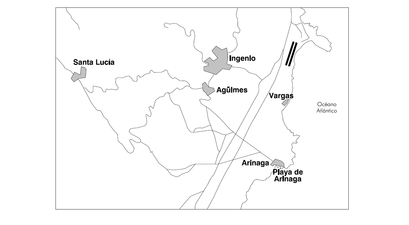
Zones sensitive to noise:
FLIGHT PROCEDURES
ATS SURVEILLANCE SYSTEMS
ATS surveillance systems at Gran Canaria Airport may be used in the provision of the aerodrome control service to carry out the following tasks:
-
Supervision of flight paths of aircraft on final approach;
-
Supervision of flight paths of other aircraft in the vicinity of the aerodrome;
-
Application of separation between consecutive departing aircraft, as laid down in RCA-4.6.7.3; and
-
Provision of navigation assistance to VFR flights.
All the functions above will be suspended in the event of a simultaneous unavailability of Gran Canaria radar.
Likewise, the provision of functions b) and d) in the eastern half of the ATZ below 400 ft AMSL and in the western half of the ATZ below 2300 ft AMSL, is not guaranteed.
LOW VISIBILITY PROCEDURES (LVP)
Low Visibility Procedures (LVP) are not available at Gran Canaria Airport.
THE MOVEMENT AREA OPERATIONAL STANDSTILL PROCEDURE (PPOAM)
Gran Canaria Airport has a "Movement Area Operational Standstill Procedure when RVR is lower than 550 m (PPOAM 550)" to maintain safety in the movement area in circumstances of low visibility, which consists of the following phases:
PHASE I: NOTICE
This will be initiated when:
- 800 m ≥ RVR≥ 550 m,
- 1000 m ≥ VIS ≥ 800 m, if the RVR value is not available, or, the prevailing visibility being greater than 1000 m, the visibility in the NNE-SSW direction is lower.
Notification to all concerned services and users to prepare.
PHASE II: OPERATIONAL STANDSTILL
This will be initiated when:
- RVR < 550 m or
- VIS < 800 m, if the RVR value is not available, or, the prevailing visibility being greater than 800 m, the visibility in the NNE-SSW direction is lower.
TWR shall not authorize operations while these conditions persist, except special operations provided for in the procedure.
PHASE III: RESUMPTION OF OPERATIONS
This will be initiated when:
-
RVR ≥ 800 m or
-
VIS ≥ 1000 m, either the prevailing or in the NNE-SSW direction (if the RVR value is not available)
Information for pilots: Defined meteorological minima for procedure.
PHASES |
RVR (m) |
VIS (1) |
|---|---|---|
Phase I - NOTICE |
< 800 and/and ≥ 550 m |
1000 m ≥ VIS ≥ 800 m |
Phase II - OPERATIONAL STANDSTILL |
< 550 m |
VIS < 800 m |
Phase III - RESUMPTION OF OPERATIONS |
≥ 800 m |
VIS ≥ 1000 m |
(1) VIS values only applicable when the RVR value is not available |
||
Uncertainty regarding the position on the manoeuvring area
When in doubt about the position of the aircraft relative to the manoeuvring area:
-
if you recognize that it is not on a runway, stop the aircraft and notify ATC immediately (including the last known position).
-
if you recognize that it is on a runway, notify ATC immediately (including the last known position) and vacate the runway as soon as possible, if you can find an appropriate taxiway nearby, unless ATC indicates otherwise, and then stop the aircraft.
SIDE STEP IN CONVENTIONAL MANOEUVRES
As there are parallel runways at Gran Canaria Airport, approaches to Thresholds 03L and 21R with side step may be cleared respectively on 03R and 21L.
The approach control service may clear a conventional approach manoeuvre with SIDE STEP to the parallel runway in the following procedures:
-
LOC Z RWY 03L
-
LOC Y RWY 03L
-
LOC X RWY 03L
-
VOR RWY 03L
-
LOC Z RWY 21R
-
LOC Y RWY 21R
-
VOR RWY 21R
In all cases, the approach altitude minima to be used to SIDE STEP shall be those of the circling.
In the event of a missed approach, the procedure shall be according to the IAC for which the aircraft was cleared.
SPEED CONTROL
Speed Control is essential for safe and smooth operations, especially in dense traffic and during final approach phase.
Spacing provided between aircrafts aims to achieve maximum runway utilization within the parameters of minimum separation (including wake turbulence separation).
These speeds are mandatory for separation purposes and standardized approach procedures at Gran Canaria Airport.
Except otherwise instructed by ATC, pilots shall comply with the following speed restrictions:
For ILS and LOC manoeuvres.
-
MAX IAS 250 kt at FL100 or MAX IAS corresponding to the designated points.
-
IAS 210 kt at 12.0 DME ILS.
-
IAS 190 kt at 9.0 DME ILS.
-
IAS 160 kt at 4.0 DME ILS; or equivalent distance to threshold in case of DME ILS U/S.
For the rest of manoeuvres, the speed restrictions will appear on your corresponding chart.
All speed restrictions are to be flown as accurately as possible. Aircraft unable to conform to these speeds due to weather conditions, aircraft performance or other operational reasons, should inform ATC immediately and state what speeds might be used. In the event of a new (non speed related) ATC clearance being issued, pilots are not absolved from the requirement to maintain a previously allocated speed.
Non-compliance with speed control instructions may lead an aircraft to be excluded from the planned approach sequence.
CONTINUOUS DESCENT OPERATIONS
Depending on traffic situation, and if no need for interrupting the descent is foreseen, aircraft will be cleared to proceed to a standard arrival (STAR), or by means of a "direct to" clearance to an intermediate fix of the STAR, to the IAF, to an intermediate approach fix or to the IF, to the minimum altitude of the IAF or the IF of the instrumental procedure (IAC), in order to allow a continuous descent operation.
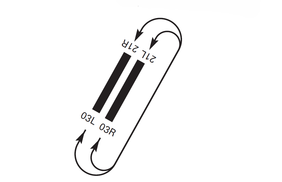
AD TRAFFIC CIRCUIT
POSSIBLE ILS SIGNAL INTERFERENCE
Due to aircraft crossing the runway or vacating it at the end, short-duration interference with the glide path or localizer signal may occur.
ADDITIONAL INFORMATION
OBLIGATORY USE OF HANDLING AGENT
All flights authorized to operate at the airport must have engaged an authorized ground Handling Agent, to be responsible for the transfer of passengers and/or flight crew within the restricted areas or those with security controls, as well as for possible carriage or movement of the aircraft in cases of emergency or when so requested by the airport.
It is mandatory to ensure that they possess the appropriate means for such carriage.
ANIMAL CONTROL SERVICE
Opening times: From sunrise to sunset.
AREAS WHERE BIRDS GATHER
Possible presence of birds due to the different points of attraction inside the airport and in the nearby environment, as described below:
-
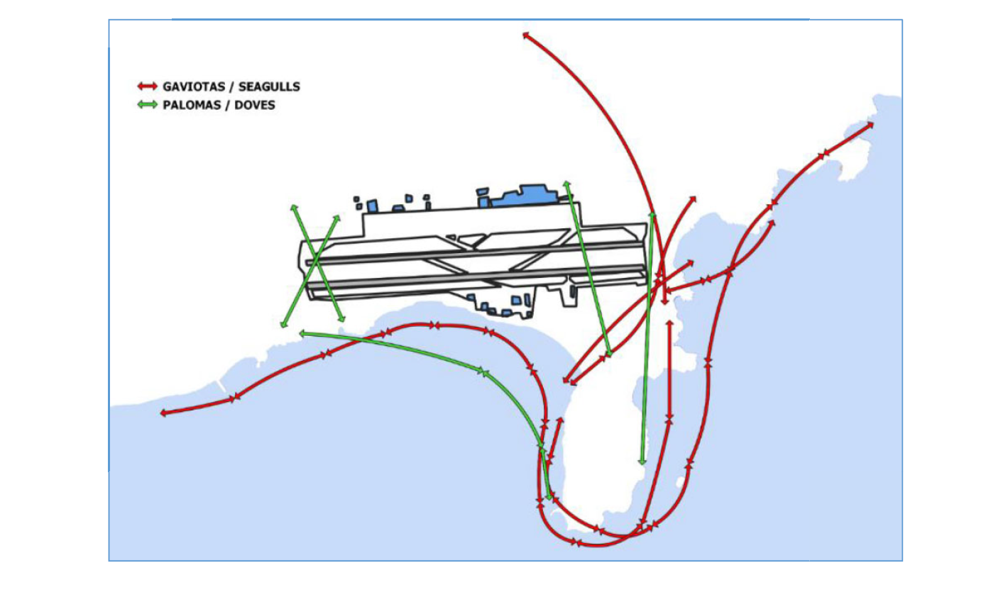
Possible presence of seagulls, especially the resident species yellow-legged gull, with nesting populations on the cliffs in the airport surroundings, with a greater presence of lesser black-backed gulls during the winter. Daily crossing at sunrise and sunset, to the North (Ecoparque Gran Canaria Norte) and to the South (Ecoparque Juan Grande), along the coast and crossing THR 21 towards the irrigation pools in the island inland.
-
Possible presence of wild rock doves, with homing pigeons representing the largest group, especially with the presence of dovecotes in towns near the airport. Crossing by both thresholds.
-
Possible presence of small birds of prey such as the common kestrel, especially during the first flights of chicks and the dispersion of juveniles, between May and July.
MOVEMENT OF BIRDS
WIND PHENOMENA
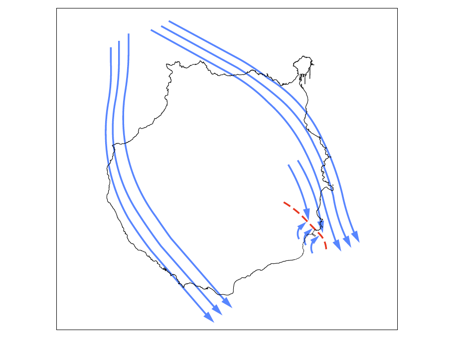
The shape and elevation of Gran Canaria island (1950 m), the location of the airport and the relief of its surroundings are decisive factors which make relief wind shear the meteorological phenomenon of greatest impact at the airport, although only in exceptional circumstances does it come to have a significant effect on operations.
North configuration (RWY 03). Situation of reinforced N-NW trade wind
The windward diffluence of the trade wind (~70% of the year), with a strong N-NW component, and most common in spring and early summer, generates a convergence line to the South of the airport, whose position may oscillate, depending on the direction of the synoptic wind, with relief wind shear present during different sectors of the approach, between Castillo de Romeral and RWY 03. Aircraft may find they are affected by tailwind during part of their approach path, and on crossing the convergence line, meet positive wind shear prompted by the sudden switch from tailwind to headwind. This wind shear is often reinforced by gusting winds, of more than 40 kt, with greater impact on operations at the airport.
The height of the thermal inversion typical of the trade wind is a factor which increases the disturbance of the flow due to the island effect. When the inversion is below 2000 m, the windward diffluence of the island is accelerated on the flanks, because it has been compressed at very low levels (on occasions, the inversion may be below 500 m). On the other hand, when the inversion layer is above 2000 m, and the synoptic wind exceeds 15-20 kt, part of the flow may be able to surmount the relief, giving rise to a strong, gusting downhill wind, which is often channelled along the gullies which open out in the vicinity of the airport, principally those of Tirajana and Guayadeque on the approach to RWY 03, and Silva on the approach to RWY 21, accentuating the wind shear in those areas.
South configuration (RWY 21). Situation of wind of SW component
The most common general synopsis is a squall to the W or NW of Canarias, with the islands standing in the sector of SW winds. A disturnace of the wind is generated on the East coast of the island of Gran Canaria, with a convergence line to the North of the airport, on the approach path to RWY 21, and the presence of relief wind shear which affects aircraft on the glide path. In these situations, the instability associated to the squall is superimposed, adding convective wind shear to that of the relief, and even gusts blowing down the slope or microbursts, depending on the position of the squall itself and its associated fronts. In the absence of inversion, the strong wind, in combination with the relief perturbation suffered and the convective vertical wind shear associated to the storms, makes these highly unstable situations those which may cause the wind shear of greatest impact, a fact underlined by the large number of missed operations prompted by this kind of squall in recent years. These circumstances tend to arise in autumn and winter.
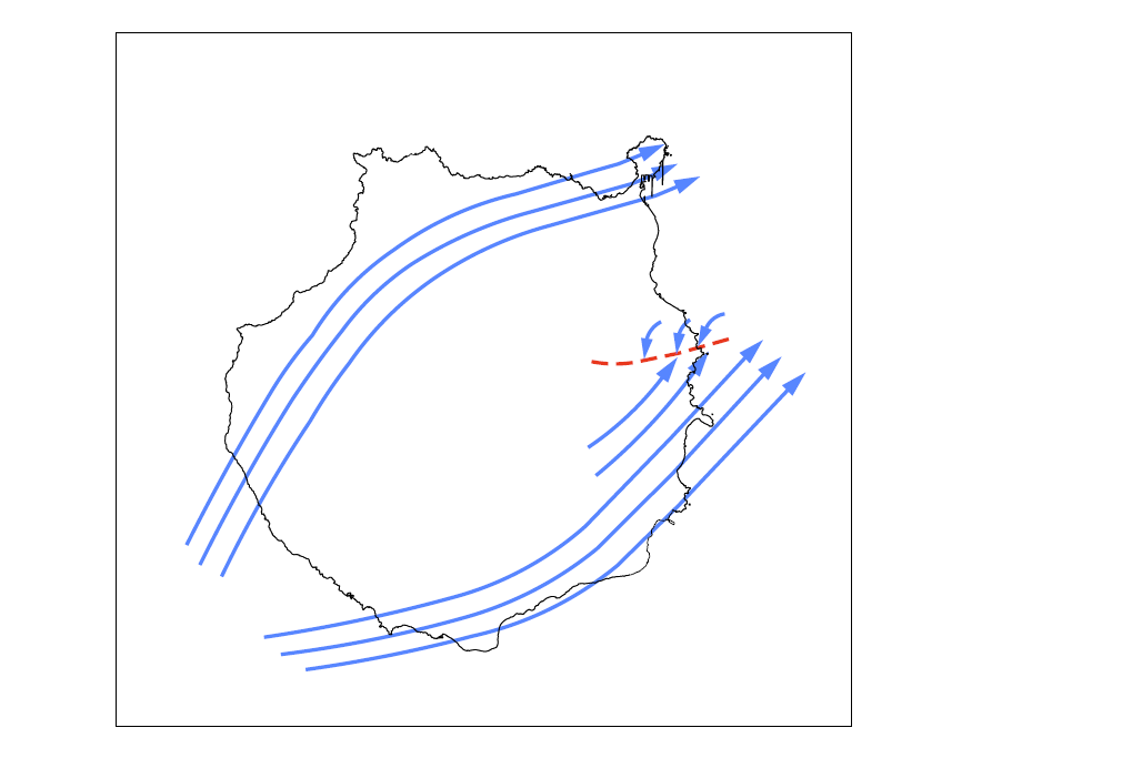
Apart from these situations, sea breeze wind shear may arise in circumstances of barometric swamp, especially at the end of the summer and early autumn. Pure West winds could prompt wind shear on the runway, with a wind of South component for RWY 03 or North for RWY 21, the convergence line being found at the airport itself, just between the two thresholds.
AERONAUTICAL CHARTS RELATED TO AN AERODROME CHARTS RELATED TO AN AERODROME
The list of charts related to the aerodrome can be found on the link below:
VISUAL SEGMENT SURFACE (VSS) PENETRATION
The instrument approach procedures affected can be found below:
IAC 1 ILS Z RWY 03L: direct approach.
IAC 2 ILS Y RWY 03L: direct approach.
IAC 3 ILS X RWY 03L: direct approach.
IAC 4 LOC Z RWY 03L: direct approach.
IAC 5 LOC Y RWY 03L: direct approach.
IAC 6 LOC X RWY 03L: direct approach.
IAC 8 RNP (LPV ONLY) RWY 03L: LPV.
IAC 9 RNP (LPV ONLY) RWY 03R: LPV.
IAC 11 RNP Y RWY 21L: LNAV, LNAV/VNAV.
IAC 16 VOR RWY 21R: direct approach.
IAC 18 RNP Y RWY 21R: LNAV, LNAV/VNAV.