LERS AD 2 AERODROME DATA
AERODROME LOCATION INDICATOR AND NAME AERODROME LOCATION INDICATOR - NAME
LERS - REUS
AERODROME GEOGRAPHICAL AND ADMINISTRATIVE DATA
| ARP | 410851N 0011002E. See AD 2-LERS ADC. | |
| Distance and direction from the city | 3 km E. | |
| Elevation | 71 m / 233 ft. | |
| Geoid undulation | 49.05 m ± 0.05 m. (1) | |
| Reference temperature | 29°C. | |
| Low average temperature | 8ºC. | |
| Magnetic variation | 1ºE (2020) | |
| Annual change | 7.6'E | |
| AD administration | Aena. | |
| Address | Aeropuerto de Reus; 43204 Reus; Tarragona. | |
| TEL | +34-977 779 885 / 04 | |
| FAX | No. | |
| AFTN | LERS | |
| REUcecoa@aena.es | ||
| Approved traffic | IFR/VFR. (2) | |
| Remarks | (1) For all the AD points. (2) Fees shall be paid preferably by card or virtual POS. (3) For reasons of apron capacity: Except for special reasons, all General Aviation, Business Aviation, Air taxis, Training flights, and State aircraft operations shall comply with the following procedure:
IFR and VFR flights without prior clearance may be rejected. |
OPERATIONAL HOURS
| Airport | V: 0600-2200 PS 1 HR PPR (1). I: 0700-2100 PS 1 HR PPR (1). |
|
| Customs and Immigration | HR AD. | |
| Health and Sanitation | No. | |
| AIS | H24 (2). | |
| ARO | HR AD (3). | |
| MET briefing | V: 0500-2200 1 HR PPR; I: 0600-2100 1 HR PPR. |
|
| ATS | V: 0545-2220, I: 0645-2120. In case PPR is activated: V: 0545-2320, I: 0645-2220. |
|
| Fuelling | HR AD. | |
| Handling | HR AD. | |
| Security | HR AD. | |
| De-icing | No. | |
| Remarks | Airport hours of activity: V: 0545-2220, I: 0645-2120. In case PPR is activated: V: 0545-2320, I: 0645-2220. (1) PPR for commercial aviation only. (2) Centralised AIO Office - International NOTAM Office.
(3) ARO service provided from the operations office of the airport. |
HANDLING SERVICES AND FACILITIES
| Cargo facilities | No. | |
| Fuel types | AVGAS 100LL, JET A-1. | |
| Oil types | W100. | |
| Refuelling capacity | JET A-1 (1):
AVGAS 100 LL (1): 1 tanker 3000 L, 2.33 L/s. |
|
| De-icing facilities | No. | |
| Hangar space | No. | |
| Repair facilities | No. | |
| Remarks | It is mandatory to have a handling agent for all commercial operations. For non-commercial operations, it is mandatory to have a handling agent for aircraft parked on ramp AG3 or commercial apron. On arrival operations, passengers and crews must wait for their handling agent. Ramp agents: SOUTH
Ramp agents may attend commercial aviation as well as general aviation. Ground handling agent with established maximum fee that may be charged as payment for services rendered to customers. These services include the passenger and crew transport from the aircraft and the terminal building and vice versa. General Aviation ramp agents: UNITED AVIATION SERVICES, SL (General Aviation).
JETEX EXECUTIVE AVIATION SPAIN (General Aviation).
GENERAL AVIATION SERVICES.
(1) Request for fuel supply: EXOLUM AVIATION S.A.
|
PASSENGER FACILITIES
| Hotels | No. | |
| Restaurant | Yes. | |
| Transportation | Buses, taxis and hire cars. | |
| Medical facilities | No. | |
| Bank/Post Office | Banking machine/Post box. | |
| Tourist information | Yes. | |
| Remarks | None. |
RESCUE AND FIREFIGHTINGFIRE FIGHTING SERVICES
| Fire category | 7 (1). | |
| Rescue equipment | In accordance with the fire category published. | |
| Removal of disabled aircraft | Brackets and hydraulic jacks for aircraft up to 2500 kg. Dollies for aircraft recovery with maximum load 5, 10 and 30 TM. Tow bars of 5 and 10/30 TM. Tractors and push-back bars of the handling companies. Cranes not belonging to AD, with no weight limit (2). | |
| Remarks | (1) Response time less than 3 min, with an operational objective of less than 2 min. (2) Responsability for the coordination of operations in the removal of disabled aircraft: CECOA office (Airport coordination centre). Contact data can be found in item 2. |
RUNWAY SURFACE CONDITION ASSESSMENT AND REPORTING, AND SNOW PLAN
| Type of clearing equipment | Not applicable. | |
| Clearance priorities | Not applicable. | |
| Use of material for movement area surface treatment | Not applicable. | |
| Specially prepared winter runways | Not applicable. | |
| Remarks | Runway surface condition assessment and reporting in accordance with the Global Reporting Format (GRF) methodology described in AD 1.2.2. Aerodrome in service during all seasons of the year. |
APRONS, TAXIWAYS AND CHECK LOCATIONS/POSITIONS DATAMOVEMENT AREA DETAILS
| Apron | Surface: Concrete. Strength: PRKG 1 to 7: PCN 15/R/A/W/T; 8 to 18: PCN 80/R/A/W/T; 31 to 34: PCN 110/R/A/W/T. |
|
| Taxiways | Width: 23 m, EXC T0: 20.85 m. Surface: Asphalt. Strength:
|
|
| Check locations | Altimeter: Apron ELEV 75 m/246 ft. VOR: No. INS: See AD 2-LERS PDC. |
|
| Remarks | None. |
Surface movement guidance and control system and markingsTAXIING GUIDANCE SYSTEM AND MARKINGS
| Taxiing guidance system | Runway-holding positions, stop bars (1), intermediate holding positions (1), runway guard lights, boards (1) and stands. | |
| RWY markings | Designators, threshold, displaced threshold RWY 07, aiming point, touchdown zone, side stripe and centre line. | |
| TWY markings | Edge and centre line. | |
| Remarks | (1) LED lighting. |
AERODROME OBSTACLES
| Obstacles in Approach, Take-Off Climb, Conical, Inner Horizontal, Transitional, Inner Transitional and Balked Landing Surfaces established in ICAO Annex 14; and the areas 2A and 3 established in ICAO Annex 15. Those penetrating these surfaces are identified in the CSV file as "Relevante_Relevant = Si/Yes". |
See Item 10 and Data Set.s section. |
| Remarks | See AD 2-LERS AOC. |
Meteorological information providedMETEOROLOGICAL SERVICE PROVIDED
| MET office | Reus EMAe. | |
| HR | V: 0500-2200 1 HR PPR; I: 0600-2100 1 HR PPR. Outside these hours, a half-hourly METAR AUTO will be issued. | |
| METAR | Half-hourly. | |
| TAF | 24 HR. | |
| TREND | No. | |
| Briefing | In person and by telephone. | |
| Flight documentation/Language | Charts and plain language / Spanish. | |
| Charts | Forecast significant, and wind and temperature at altitude, maps. | |
| Supplementary equipment | Clouds, lightning and radar information image display. | |
| ATS unit served | TWR, APP. | |
| Additional information | Valencia OMAe (LEVA): H24
Reus EMAe: HR AD
|
|
| Remarks | Aerodrome climatological summary available. Aerodrome warnings available. |
RUNWAY PHYSICAL CHARACTERISTICS
| RWY | Direction | DIM (m) | THR PSN | THR ELEV TDZ ELEV |
SWY(m) | CWY(m) | Strip (m) | OFZ | RESA(m) | RWY/SWY SFC PCN |
|---|---|---|---|---|---|---|---|---|---|---|
| 07 (1) | 068.94°GEO 068ºMAG |
2459 x 45 | 410841.84N 0010931.71E |
THR: 70 m/230 ft TDZ: No |
No | 240 x 150 | 2579 x 280 | No | 240 x 120 | RWY: ASPH PCN 72/F/A/W/T SWY: No |
| 25 (2) | 248.95°GEO 248°MAG |
2459 x 45 | 410907.34N 0011059.35E |
THR: 71.2 m/233 ft TDZ: 71.2 m/233 ft |
No | 150 x 150 | 2579 x 280 | No | 240 x 150 | RWY: ASPH PCN 72/F/A/W/T SWY: No |
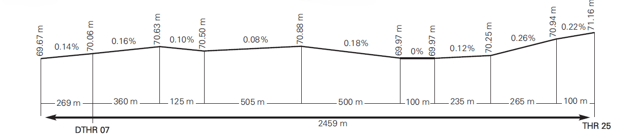
Remarks: (1) THR RWY 07 displaced 269 m, last 269 m of RWY 25 PCN 42/F/A/W/T. |
||||||||||
Profile
DECLARED DISTANCES
| RWY | TORA (m) | TODA (m) | ASDA (m) | LDA (m) |
|---|---|---|---|---|
| 07 | 2459 | 2699 | 2459 | 2190 |
| 25 | 2459 | 2609 | 2459 | 2459 |
| 07 INT A2 | 2157 | 2397 | 2157 | - |
| 25 INT C | 1828 | 1978 | 1828 | - |
| Remarks | None. | |||
APPROACH AND RUNWAY LIGHTING
| Runway | 07 | |
| Approach | Simple, 420 m. LIH. Sequential. | |
| PAPI (MEHT) | 3° (16.75 m / 55 ft). | |
| Threshold | Wing bars. | |
| Touchdown zone | No. | |
| Runway centre line | No. | |
| Runway edge | 2459 m: 269 m red; 1590 m white; 600 m yellow. LIH. Distance between lights: 47.5 m. |
|
| Runway end | Red | |
| Stopway | No. | |
| Remarks | None. |
| Runway | 25 | |
| Approach | Precision CAT I, 900 m. LIH. | |
| PAPI (MEHT) | 3° (14.94 m / 49 ft). (1) | |
| Threshold | Green with wing bars. | |
| Touchdown zone | No. | |
| Runway centre line | No. | |
| Runway edge | 2459 m: 1859 m white; 600 m yellow. LIH. Distance between lights: 47.5 m. |
|
| Runway end | Red. | |
| Stopway | No. | |
| Remarks | (1) PAPI not suitable for use by ACFT A332. |
OTHER LIGHTING, SECONDARY POWER SUPPLY
| ABN/IBN | No. | |
| WDI | 1 near THR 07, 1 near THR 25. LGTD (1). | |
| TWY lighting | Edge (1). | |
| Apron lighting | Floodlighting poles and reflective edge. | |
| Secondary power supply | Engine generators that provides the whole lighting system with a maximum switch-over time (light) of 15 seconds, according to Annex 14. | |
| Remarks | (1) LED lighting. |
HELICOPTER LANDING AREA
| Position |
|
|
| Elevation |
|
|
| Dimensions, surface, maximum weight, marking |
|
|
| Direction | INFO NO AVBL. | |
| Declared distances | INFO NO AVBL. | |
| Ligthing | No. (1) | |
| Remarks | (1) Apron lighting. FATO TLOF T0 is likewise declared, always under ATC coordination and authorisation. Following coordination with ATC, helicopters in hangars will taxi by air or by land, or they will be towed (depending on their origin), to the TLOF marked on TWY T0. Once they reach the marked TLOF, they will take-off in runway heading, parallel to it (aligned with the runway, heading 068º or 248º, depending on the runway in use). Taxiing will also be restricted for other aircraft on TWY T0 during the take-off manoeuvre. |
Air traffic services airspaceATS AIRSPACE
| Designation | CTR REUS. | |
| lateral limits | 405918N 0005554E, arc of 14.0 NM radius centred on DVOR/DME RES, 410712N 0005117E, 410724N 0005355E, arc of12.0 NM radius centred on DVOR/DME RES, 411034N 0005402E, 411414N 0010824E, 411425N 0011527E, 411718N 0012042E, arc of12.0 NM radius centred on DVOR/DME RES, 410858N 0012536E, following the coast line, 410758N 0012407E, 410300N 0011100E, 405918N 0005554E. | |
| Vertical limits | SFC-FL075. | |
| Airspace class | D. | |
Unit Language |
REUS TWR. ES/EN. |
|
| Transition altitude | 1850 m / 6000 ft. | |
| Hours of applicability | - | |
| Remarks | None. |
| Designation | ATZ REUS. | |
| Llateral limits | Cylinder radius 8 km centred on ARP (1). | |
| Vertical limits | SFC-3000 ft HGT (2). | |
| Airspace class | D. | |
Unit Language |
REUS TWR. ES/EN. |
|
| Transition altitude | - | |
| Hours of applicability | - | |
| Remarks | (1) Or the ground visibility, whichever is lower. (2) Or up to the cloud ceiling, whichever is lower. |
Air traffic services communication facilitiesATS COMMUNICATION FACILITIES
| Service | Call sign | FREQ | HR | Remarks |
|---|---|---|---|---|
| APP/TWR | Reus TWR | 128.880 C | HR ATS | - |
| 121.500 MHz | HR ATS | EMERG | ||
| 121.705 C | HR ATS | GMC | ||
| 257.800 MHz | HR ATS | MIL | ||
| 243.000 MHz | HR ATS | EMERG | ||
| VDF | Reus gonio | 128.875 MHz | HR ATS | - |
| ATIS | Reus Information | 120.255 C | HR ATS | - |
| D-ATIS | Reus Information | NIL | HR ATS | Provision of ATIS information via data link. |
RADIO NAVIGATION AND LANDING aidsFACILITIES
| Facility (VAR) | ID | FREQ | HR | Coordinates | ELEV DME |
Remarks |
|---|---|---|---|---|---|---|
| DVOR (1ºE) | RES | 116.850 MHz | H24 | 410837.7N 0010943.1E | - | COV 40 NM AVBL BTN:
|
| DME | RES | CH 115Y | H24 | 410837.2N 0010943.1E | 60 m | COV 40 NM AVBL BTN:
|
| NDB (1ºE) | RUS | 424.000 kHz | H24 | 410852.2N 0010846.1E | - | - |
LOC 25 (1ºE) ILS CAT I |
IRS | 110.100 MHz | H24 | 410834.2N 0010905.4E | - | 248° MAG / 2847 m FM THR 07 DESP. COV 17 NM AVBL at 3200 ft AMSL or ABV. COV 25 NM AVBL at 2800 ft AMSL or ABV. |
| GP 25 | - | 334.400 MHz | H24 | 410900.0N 0011049.0E | - | 3°; RDH 15 m; at 307 m FM THR 25 & 125 m FM RCL to the left in direction APCH. |
| ILS/DME 25 | IRS | CH 38X | H24 | 410900.0N 0011049.0E | 69 m | REF DME THR 25. |
Local aerodrome regulationsLOCAL REGULATIONS
The VFR/IFR flights will be cleared for practicing approaches and touch-and-goes, restricted according to the air traffic situation.
CROSS ENGINE START
ATC may clear cross engine start in TWY.
PREFERENTIAL RUNWAY
In Reus Airport, the preferential runway is RWY 25.
Operators shall not request operations on RWY 07 when RWY 25 is in use except for safety and/or aircraft performance reasons.
NIGHT - TIME VISUAL OPERATIONS (VFR-N)
VFR-N flights are allowed.
STANDARD TAXIING PROCEDURES
All surface movements of aircraft, towed aircraft, persons and vehicles in the manoeuvring area are subject to prior ATC clearance.
Oversteering manoeuvre may be necessary for access to stands from TWY.
Pilots shall proceed to verify the aircraft position at all times, checking that taxiing is being executed under conditions of complete safety.
Avoiding collisions with other aircraft and obstacles areas is the responsibility of:
- Pilots, when taxiing on the apron and taxiway segments not visible from TWR (see AD 2-LERS PDC)
- Ground handling companies during stand exit manoeuvres with push-back, and during towing.
- GROUND MOVEMENT
ARRIVALS:
Aircraft that have landed shall notify of the runway vacated and the exit taxiway used, awaiting taxiing instructions from TWR, with the exit taxiway being:
- When RWY 25 is in service (unless indicated otherwise by ATC):
- Via TWY A2, and aircraft shall await a "FOLLOW ME" vehicle in order to proceed with guidance to the stand.
- Via TWY A1, (only code letter A or B aircraft), and aircraft shall await a "FOLLOW ME" vehicle in order to proceed with guidance to the stand.
- Via TWY B (helicopters only), taxiing via TWY T2 until the apron boundary where they shall await a "FOLLOW ME" vehicle in order to proceed with guidance to the stand.
- When RWY 07 is in service:
- By the end of the runway, unless indicated otherwise by ATC, taxiing via TWY T4, TWY T3 and TWY T2 until the apron boundary, where they shall await a "FOLLOW ME" vehiclein order to proceed with guidance to the stand.
The "FOLLOW ME" vehicle guidance service shall also be provided in exceptional situations when requested by TWR or at the request of the pilot and when the Procedure for Halting Operations in the Manoeuvring Area (PPOAM in Spanish) is activated, or during adverse weather conditions.
DEPARTURES:
As instructed by ATC, the aircraft will access the runway for take-off via:
- RWY 25 in use:
- TWY DL/DR.
- INT C (prior coordination with ATC).
- RWY 07 in use:
- TWY A1.
- INT A2 (prior coordination with ATC).
- When RWY 25 is in service (unless indicated otherwise by ATC):
- TWY T1, T2, T3 AND T4 TAXIING INCOMPATIBILITIES
An aircraft taxiing via TWY T1, T2, T3 and T4 cannot taxi behind a code letter C or higher aircraft that is holding short of runway at intersections A2, B or C.
- TWY T0 TAXIING RESTRICTIONS
Taxiing via TWY T0 is restricted to aircraft with a wingspan of 22 m or less.
Taxiing via TWY T0 may be either during daytime or night-time.
Pilots on departure, before starting to taxi, shall always contact ATC to request traffic information. Taxiing via TWY T0 beyond the runway-holding position is not permitted, under the following conditions:
- When an aircraft is on short final approach for RWY 07.
- When an aircraft is performing push-back from PRKG 1 or 2, nosing to the east.
- RAMP AG3 TAXIING RESTRICTIONS
Taxiing in and out of Ramp AG3 is limited to aircraft with a maximum wingspan of 16.5 m.
Entry and exit to and from Ramp AG3 may be both at daytime and night-time.
- AIRCRAFT TAXIING RESTRICTIONS
For turns T1 - A1 and DL - T4, aircraft B767-400 ER must oversteer on both turns.
Taxiing restricted for access to AG1 parking areas for PA-42-1000 Cheyenne 4000 aircraft.
- CODE LETTER AND NUMBER BASED TAXIING RESTRICTIONS ON TAXIWAYS
Taxiways restricted to code letter and number aircraft: D-IV, except T0: B-III.
Taxiways on apron restricted to code letter and number aircraft: Access to AG3: B-III; Access to AG1, A-II.
- RAMP AG1 TAXIING RESTRICTIONS
Taxiing in and out of Ramp AG1 is limited to aircraft with a maximum wingspan of 15 m.
Entry and exit to and from Ramp AG1 shall be during daylight hours only.
SPECIAL FEATURES OF OPERATION ON RWY 07 AND 25
When RWY 07 is in use, ATC shall restrict the use of TWY T1 and TWY A1.
In addition, in order to protect the obstacle limitation surfaces of RWY 07 and 25:
- ATC shall minimize the average delay to operations providing, as far as possible, the estimated time when clearances will be issued.
- Aircraft shall not request push-back until they are fully ready to start this.
- The push-back manoeuvre must be accomplished within five minutes of clearance by ATC.
- Aircraft shall start taxiing as soon as possible once the push-back manoeuvre is finished.
RWY 25 HOLDING POSITIONS (TWY DL / DR) INCOMPATIBILITIES
| Aircraft stopped in | Maximum code letter aircraft taxiing to | ||
| TWY DL | TWY DR | ||
| TWY DL | Code letter C | - | Code letter C |
| Code letter D | - | Code letter C | |
| Code letter E | - | Not permitted | |
| TWY DR | Code letter C | Code letter D | - |
| Code letter D | Code letter C | - | |
| Code letter E | Not permitted | - | |
OPERATION OF CODE LETTERS D AND E AIRCRAFT
Applicable to aircraft exceeding the certified aerodrome design characteristics, i.e. Code Letter E aircraft and the following Code Letter D and larger aircraft:
- Airbus A300-B2/B4
- Boeing B757-300W
- Boeing B767-200
- Boeing B767-300ER
- Boeing B767-400ER
The taxiing routes and aircraft stands established for the aforementioned aircraft are as follows:
ARRIVALS
RWY 07 in use:
Preferred runway vacating via TWY DR and taxi via TWY T4, T3, T2 and T1 to enter the apron. In the event of an approach to RWY 07, the aircraft will be instructed during taxi to hold at the intermediate holding position located on TWY T2, where it shall await ATC clearance to continue taxi via TWY T1 to enter the apron.
NOTE: When vacating the runway via TWY DR/DL, aircraft shall oversteer on the turns between RWY 25–TWY DR, TWY DR–T4 and TWY DL–T4.
RWY 25 in use:
Preferred runway vacating via TWY A2 and taxi via TWY T1 to enter the apron. When vacating via TWY A1, the pilot shall report runway vacated when abeam TWY T1.
NOTE: When vacating via TWY A1/A2, aircraft shall perform oversteering at the turn between TWY A1/A2–T1.
DEPARTURES
RWY 07 in use:
Preferred departure via TWY A2. Push-back facing East and taxi via TWY T1 to TWY A2. When accessing the runway via TWY A1, push-back shall be facing West. In case of approach on RWY 07, the use of TWY T1 and A1 is restricted; therefore, aircraft shall hold position and await further ATC instructions.
NOTE: When accessing the runway via TWY A1/A2, aircraft shall perform oversteering at the turn TWY T1–A1/A2.
RWY 25 in use:
Push-back facing East. Exit the apron via TWY T1 and taxi via TWY T2, T3 and T4 to the holding position on TWY T4, then enter the runway via TWY DR.
PARKING
Code Letter E aircraft and the B767-400ER may only park at PRKG XL.
Code Letter D aircraft may only park at PRKG 1A, 2A, 3A and XL.
CONSIDERATIONS RELATING TO PAPI:
- RWY 25 in use: code letter E aircraft should not follow the PAPI indications.
- RWY 07 in use: code letter E aircraft should not follow the PAPI indications.
OPERATION OF HELICOPTERS
The procedures to be followed by those helicopters not operating with a letter of exemption are now described.
Since there is no specific area for helicopter operations, these shall receive the same treatment as fixed-wing aircraft and shall be authorized by ATC to take off and land at the runway.
TAXIING ROUTES
RWY 25 in use:
- Departures: Helicopters shall carry out air or ground taxiing (as appropriate) via TWY T0, T1, T2, T3 and/or T4 up to holding position A1, A2, B, C or DR, as appropriate, following ATC instructions.
- Arrivals: Helicopters shall complete the final approach to the runway and shall vacate it via TWY B, unless ATC should indicate otherwise. Helicopters shall carry out air or ground taxiing, as appropriate, to the assigned stand.
RWY 07 in use:
- Departures: Helicopters shall carry out air or ground taxiing (as appropriate) via TWY T0, T1, T2, T3 and/or T4 up to holding position A1, A2, B, C or DR, as appropriate, following ATC instructions.
- Arrivals: Helicopters shall complete the final approach to the runway and shall vacate it via TWY B, unless ATC should indicate otherwise. Helicopters shall carry out air or ground taxiing, as appropriate, to the assigned stand.
Once on the apron, both air and ground taxiing shall be carried out by the entry taxiway to the stand, following its centre line marking, both on arrival and departure.
The departure operation from TLOF on TWY T0 will only be allowed in the following cases:
- If weather conditions make it advisable not to operate from the runway to guarantee operational security, with winds of around 20 kt.
- Taxiing would occur with a crosswind or tailwind, in severe weather conditions.
- Emergency situations or when so required for operational reasons.
To reduce the response times as much as possible on missions, and to avoid unnecessary risks during long taxis, helicopters participating in urgent special operations under letter of exception conditions in the terms set forth in Article 2.3.9. of the Air Circulation Regulations, the operator will request permission from ATC, who, after assessing the situation and analysing the movement of the rest of the aircraft, will authorise the operation when conditions are favourable to do so safely.
ATC will separate departures and arrivals of helicopters using FATO TLOF T0 from aircraft using RWY 07/25 as if they were aircraft using the same runway. For take-offs from TWY T0, simultaneous operations with RWY 07/25 are not allowed. The helicopters larger than the AW139 cannot operate on TWY T0 or use TLOF T0.
OPERATIONAL SAFETY REPORTS
Pilots/operator shall report to the airport as soon as possible about any accidents, incidents, occurrences or events which may have a potential operational impact and in which they may have been involved or witnessed.
The aim of these reports is the compilation of information in order to improve operational safety, independently of the mandatory reporting of the occurrence to the appropriate aeronautical authority.
Data may be sent in any format, including at least the following information:
- Date and time.
- Site.
- Parties involved (data used to identify vehicles, aircraft... involved).
- Companies implicated.
- Description of the facts.
- Any other data considered relevant (e.g. lighting conditions, weather, phase of the operation such as take-off / landing / stopover, pavement conditions).
Contact e-mail address of the airport, for the reception of operational safety reports, is the following: REUSeguridadOperacional@aena.es
In addition to notifying the airport by means of the indicated system, it is necessary to send at least basic data of the accident, incident, occurrence or event to the air traffic control service provider (ATC).
On the specific instance of safety reports related with the air traffic control service provider (manoeuvring area, flight phases and ATS airspace) these may be sent to the e-mail address: lecb.safety@enaire.es
POINT OF ENTRY FOR PASSENGERS WITH PET ANIMALS FROM THIRD COUNTRIES
To guarantee compliance with the Regulation (EU) No 576/2013 of the European Parliament and of the Council of 12 June 2013 on the noncommercial movement of pet animals and repealing Regulation (EC) No 998/2003, any Air Carrier wishing to operate at the Airport and transporting in the cabin, as a part of passenger hand baggage, the animals (pets) set out in part A of Annex I to the mentioned Regulation, must have engaged a handling agent who to be responsible for handling the same in those cases where, during the checks undertaken by the Resguardo Fiscal of the Guardia Civil or Customs Personnel of the Passenger Terminal of Reus Airport, some breach of the health requirements established in the cited regulations is detected which prompts the animal's rejection at the border.
The management of an animal rejected at the border shall include, at least, transport to the designated facilities for its temporary stay at the airport, its subsistence, veterinary care and animal welfare, and even its return to the point of origin within the periods established by the health authorities.
NOISE ABATEMENT PROCEDURES
ENGINE TEST
Engine tests need prior authorization from the CECOA.
FLIGHT PROCEDURES
ATS SURVEILLANCE SYSTEMS WITHIN THE ATZ
This may be used in supplying the aerodrome control service to perform the following functions:
- Supervision of flight path of aircraft on final approach;
- Supervision of the flight path of other aircraft in the vicinity of the aerodrome;
- Application of separation as required by the R.C.A., section 4.6.7.3, between successive departing aircraft; and
- Provision of navigation assistance to VFR flights.
Similarly, provision of the functions b) and d) is not guaranteed in the northern half of the ATZ below 1300 ft AMSL
All the functions above will be suspended in the event of unavailability of BEGAS radar.
ATS SURVEILLANCE SYSTEMS OUTSIDE THE ATZ
Within the area of responsibility of the unit, this systems may be used to provide to the controller with procedures:
- Better position information about the aircraft that are under control;
- Supplementary information about other traffic;
- Information about any important deviation by the aircraft from what has been stipulated in the air traffic control clearances, including the cleared routes and flight levels, in accordance with the following clarifications:
- Below 4000 ft AMSL and if the three radars BEGAS, EVA AITANA and MONFLORITE are operational, the foregoing services are not guaranteed.
- Below 5000 ft AMSL and in the following cases: If the BEGAS radar is operational, or both the EVA AITANA and MONFLORITE radars are operational, the foregoing services are not guaranteed.
In the event of simultaneous unavailability of the BEGAS, EVA AITANA and MONFLORITE radars, all the foregoing functions will be suspended.
LOW VISIBILITY PROCEDURES (LVP)
Low Visibility Procedures (LVP) are not available at Reus Airport.
MOVEMENT AREA OPERATIONAL STANDSTILL PROCEDURE (PPOAM)
At Reus Airport movement area operational standstill procedure is available, when RVR is below 800 m (PPOAM 800)" to maintain the safety in the movement area in low visibility conditions, with the following phases:
- PHASE I. Warning: 1100 m ≥ RVR ≥ 800 m
- PHASE II. Operational standstill: 800 m > RVR
- PHASE III. Operational resumption: RVR > 900 m
INFORMATION FOR PILOTS:
- Uncertainty regarding the position on the manoeuvring area
When in doubt about the position of the aircraft in relation to the manoeuvring area:
- If you recognize that it is not on a runway, stop the aircraft and notify ATC immediately (including the last known position).
- If you recognize that it is on a runway, notify ATC immediately (including the last known position) and vacate the runway as soon as possible, if you can find an appropriate taxiway nearby, unless ATC indicates otherwise, and then stop the aircraft.
- Failure of an aircraft
Notify the situation to ATC and wait for the arrival of assistance. In the case it is on a runway, if possible and unless ATC indicates otherwise, vacate the runway.
- Loss of visual contact between traffic
In the event of loss of visual contact with another aircraft or a vehicle with which you are maintaining your own separation, notify ATC immediately and stop the aircraft.
- Communications failure
- Departing aircraft: the aircraft shall continue by the assigned route and shall stop at the ATC clearance limit, taking extreme care, where it shall hold and wait for the arrival of an assistance vehicle.
- Arriving aircraft: if the aircraft has just landed, it shall hold after vacating the runway and wait for the arrival of an assistance vehicle.
- If the aircraft already holds ATC taxiing clearance, it shall continue by the assigned route up to the clearance limit, taking extreme care, where it shall hold and wait for the arrival of an assistance vehicle.
DESCENT PLANNING DUE TO ATC REQUIREMENTS
Unless ATC advises otherwise, arrivals to Reus AD shall plan their descent to cross the intitial points of the procedure and the speed limit points (SLP) at the flight levels specified in the standard instrument arrival (STAR).
In the case of being authorized to proceed on a direct route other than a STAR, they shall adjust their descent and speed at the appropriate regulation point.
SPEED ADJUSTMENT
Within TMA BARCELONA, unless otherwise advised by ATC, speed adjustment under radar control on departures and arrivals to Reus AD shall be in accordance with the following:
- IAS 250 kt at FL100 or below, in all departures.
- IAS 230 kt while in holding, at FL140 or below.
- IAS 250 kt at SLP.
- Speed adjustment on approach:
- IAS 220 kt when leaving an IAF.
- IAS between 180 kt and 170 kt on receiving the final interception heading for the localizer.
- IAS 160 kt when intercepting the glide path on the FAP; this speed shall be maintained up to 4 NM from the threshold.
- Aircraft with a cruising IAS below those indicated above shall maintain cruising speed up to the adjustment point affecting them.
ATC shall be informed of the speeds that may be maintained, if unable to comply with the speed adjustments above.
AIRCRAFT AIR/GROUND COMMUNICATIONS FAILURE PROCEDURES
An aircraft which experiences a communications failure shall immediately respond on the SSR mode 7600.
- When failure occurs during a STAR procedure before the IAF: Proceed to the assigned IAF for the authorized STAR, maintaining the last approved flight level or altitude acknowledged and begin holding. Initiate the descent after completing one holding pattern, or at the EAT when received, whichever is later, to accomplish a published IFR approach to the RWY in service for arrival, in order to land within the following 30 minutes.
- When failure occurs on radar vector before the IAF: Proceed to the STAR in the most direct way and up to the IAF, following the communications failure procedure while on the STAR procedure.
- When failure occurs on radar vector after the IAF: Maintain the last acknowledged authorized altitude and proceed to the final path for approach to accomplish this and land. If unable to do so, accomplish the missed approach procedure with comunications failure.
- When failure occurs during the missed approach: Do not initiate the missed approach before the MAPT. Intercept the missed approach procedure in accordance with the corresponding IAC for approach. Execute at least one holding pattern at the holding fix to accomplish the approach and landing.
- When failure occurs during a SID: Follow the SID up to the TMA exit point, climbing to the last approved flight level acknowledged or to the minimum safety altitude, whichever is higher; maintain this level for 3 minutes, complying in any case with the maximum flight levels specified for aircraft with communications failure on the appropriate departure chart, and then continue flight in accordance with the updated FPL.
- When failure occurs during a departure with radar vector: Intercept in the most direct way the last SID procedure given by ATC, climbing to the last approved flight level acknowledged or at the minimum safety altitude, whichever is higher; complying in any case with the maximum flight levels specified for aircraft with communications failure on the appropiate departure chart, and then continue flight in accordance with the updated FPL.
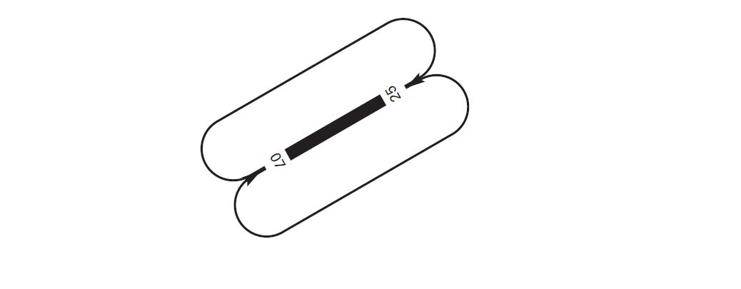
AD TRAFFIC CIRCUIT
ADDITIONAL INFORMATION
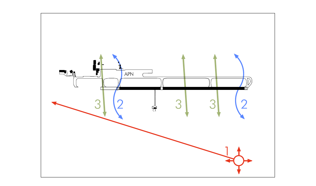
BIRDS MOVEMENT AREAS
Caution is adviced due to the presence of birds in RWY 07/25.
Flows of birds:
- Gulls.
- Swifts, during spring and summer, especially on hot days with little wind.
- Pigeons, throughout all the year, very frequent from January to April.
Many other birds (lapwings, grey herons, cattle egrets, buzzards, owls, eaglets, etc) may be seen throughout the year, with no recognizable patterns which could allow to forecast their presence.
ACTIVITIES IN THE VICINITY OF THE AERODROME
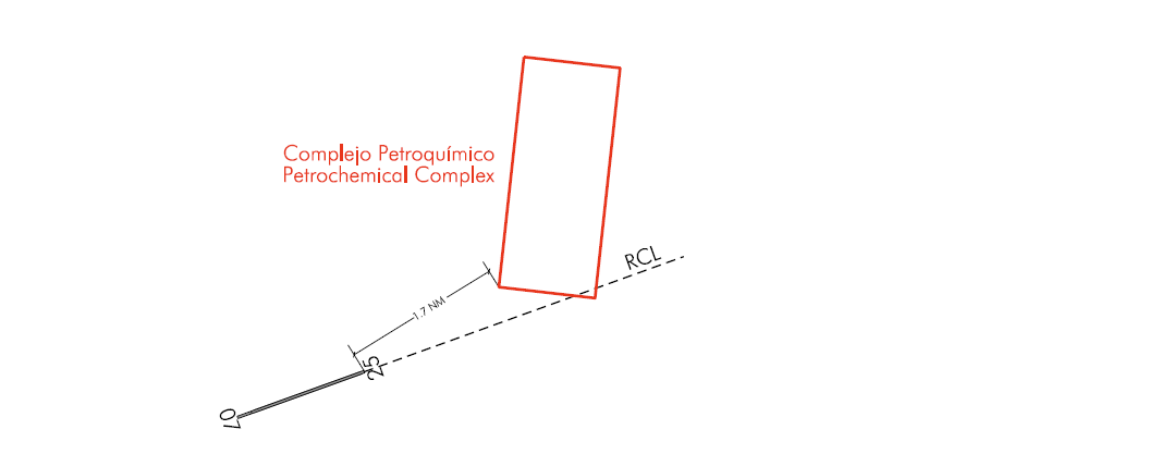
A petrochemical complex is located to the north-east of the aerodrome where hot gases are released which, when overflown, may induce vibrations. This complex is located within the area defined by the coordinates 411215.61N 0011259.36E, 411210.30N 0011414.99E, 410953.71N 0011358.95E and 410959.01N 0011243.38E.
Aeronautical charts related to an aerodromeCHARTS RELATED TO THE AERODROME
The list of charts related to the aerodrome can be found on the link below:
VISUAL SEGMENT SURFACE (VSS) PENETRATION
The instrument approach procedures affected can be found below:
IAC 1 VOR RWY 07: Direct approach.
IAC 3 RNP Y RWY 07: LNAV, LNAV/VNAV.
IAC 4 ILS Z RWY 25: Direct approach.
IAC 6 LOC Z RWY 25: Direct approach.
IAC 8 VOR RWY 25: Direct approach.