LEVT AD 2 AERODROME DATA
AERODROME LOCATION INDICATOR AND -NAME
LEVT - VITORIA
AERODROME GEOGRAPHICAL AND ADMINISTRATIVE DATA
ARP |
425258N 0024328W. See AD 2-LEVT ADC. |
|
Distance and direction from the city |
8 km NW. |
|
Elevation |
513 m / 1682 ft. |
|
Geoid undulation |
50.75 ± 0.05 m (1). |
|
Reference temperature |
26°C. |
|
Low average temperature |
3ºC. |
|
Magnetic variation |
1°E (2025). |
|
Annual change |
9.8'E. |
|
AD administration |
Aena. |
|
Address |
Aeropuerto de Vitoria, 01196 Vitoria-Gasteiz - Araba-Álava. |
|
TEL |
+34-945 163 500/518 |
|
| FAX | No. |
|
AFTN |
LEVT. |
|
Approved traffic |
IFR/VFR. |
|
Remarks |
SITA: VITOOYA. (1) For all AD points. |
OPERATIONAL HOURS
Airport |
H24. |
|
Customs and Immigration |
HR AD. |
|
Health and Sanitation |
See GEN 1.4. |
|
AIS/ARO |
H24 (1) (2). |
|
MET briefing |
H24. |
|
ATS |
H24. |
|
Fuelling |
HR AD. |
|
Handling |
HR AD. |
|
Security |
H24. |
|
De-icing |
HR AD. |
|
Remarks |
(1) Centralised AIO Office - International NOTAM Office
(2) ARO service provided from operations office of the airport. |
HANDLING SERVICES AND FACILITIES
Cargo facilities |
Up to 11000 kg. |
|
Fuel types |
JET A-1, 100LL. (1) |
|
Oil types |
AEROSHELL, W-100. |
|
Refuelling capacity |
No limitations. |
|
De-Icing facilities |
In all stands, except those of general aviation (107 to 116), with hot water and glycol for removing ice from the ACFT. |
|
Hangar space |
No. |
|
Repair facilities |
No. |
|
Remarks |
(1) Fuel: SLCA
Ramp agents: SOUTH
WFS Servicios Aeroportuarios, S.A. (Only cargo)
AviaVIP (Only Executive Aviation)
|
PASSENGER FACILITIES
Hotels |
No. |
|
Restaurant |
No. |
|
Transportation |
Taxies. |
|
Medical facilities |
No. |
|
Bank/Post Office |
No / No. |
|
Tourist information |
Yes. |
|
Remarks |
None. |
RESCUE AND FIREFIGHTING SERVICES
Fire category |
7, HR AD (1) (2). |
|
Rescue equipment |
In accordance with the fire category. |
|
Removal of disabled aircraft |
The Airport has its own equipment to remove disabled aircraft weighing up to 10 tonnes. Aircraft weighing more than 10 tonnes shall be removed via external services, prior request and in the presence of the aircraft owner/operator and at itself expense. Contact information of the Aerodrome coordinator for transport of aircraft out of service:
|
|
Remarks |
(1) For other fire categories, prior request, consult NOTAM in force. (2) Response time of the rescue and fire fighting services is less than 3 MIN, with an operational objective less than 2 MIN. |
RUNWAY SURFACE CONDITION ASSESSMENT AND REPORTING, AND SNOW PLAN
Types of clearing equipment |
Trucks fitted with plough blades, bulldozers and dissolvent spreaders. |
|
Clearance priorities |
Runway, taxiways serving the runway, apron 1 and PRKG 7 to 12 in apron 2, service roads 1 and 2, and access roads to them. |
|
Use of material for movement area surface treatment |
Potassium acetate (KAC) and urea (UREA). |
|
Specially prepared winter runways |
Not applicable. |
|
Remarks |
Period of application of snow plan: 1-NOV to 31 MAR. Runway surface condition assessment and reporting in accordance with the Global Reporting Format (GRF) methodology described in AD 1.2.2. Aerodrome in service during all seasons of the year. |
APRONS, TAXIWAYS AND CHECK LOCATIONS/POSITIONS DATAMOVEMENT AREA DETAILS
Apron |
Surface: Hydraulic concrete. Strength: APN 1: Ramp 1: PCN 45/R/B/W/T. APN 2: Ramp 2:
|
|
Taxiways |
Width: 23 m. Surface: Hydraulic concrete. Strength:
|
|
Check locations |
Altimeter: Apron: ELEV 507 m/1663 ft. VOR: TWY E (425255.05N 0024351.49W), R-286 VFD / 0.3 DME VFD. Only code letter C or lower aircraft. INS: No. |
|
Remarks |
TWY centre line: see INSIGNIA and Data Set. |
SURFACE MOVEMENT GUIDANCE AND CONTROL SYSTEM AND MARKINGSTAXIING GUIDANCE SYSTEM AND MARKINGS
Taxiing guidance system |
NO-ENTRY lighted sign, runway-holding positions, intermediate holding positions, runway guard lights, stop bars, intermediate holding position lights and stands. |
|
RWY markings |
Designators, threshold, centre line, side stripe, touchdown zone, aiming point, rapid exit taxiway indicator markings on RWY 22 (C1). |
|
TWY markings |
Centre line, side stripe and enhanced centre line in T1 and T7. |
|
Remarks |
Retroreflective markers on the edge of aprons 1 and 2, and TWY (except TWY E). |
AERODROME OBSTACLES
Obstacles in Approach, Take-Off Climb, Conical, Inner Horizontal, Transitional, Inner Transitional and Balked Landing Surfaces established in ICAO Annex 14; and the areas 2A and 3 established in ICAO Annex 15. Those penetrating these surfaces are identified in the CSV file as "Relevante_Relevant = Si/Yes". |
See Item 10 and Data Set. |
|
Remarks |
See AD 2-LEVT AOC. |
METEOROLOGICAL INFORMATION PROVIDEDMETEOROLOGICAL SERVICE PROVIDED
MET office |
Vitoria EMAe. |
|
HR |
H24. |
|
METAR |
Half-hourly. |
|
TAF |
24HR. |
|
TREND |
No. |
|
Briefing |
In person and by telephone. |
|
Flight documentation/Language |
Charts and plain language / Spanish. |
|
Charts |
Significant forecasted and wind and temperature in altitude maps. |
|
Supplementary equipment |
Clouds, lightning image and radar information display. |
|
ATS unit served |
TWR, APP. |
|
Additional information |
Santander OMAe (LESD): H24
Vitoria EMAe: H24
|
|
Remarks |
Aerodrome climatological summary available. Aerodrome warnings available. |
RUNWAY PHYSICAL CHARACTERISTICS
RWY |
Direction |
DIM (m) |
THR PSN |
THR ELEV TDZ ELEV |
SWY (m) |
CWY (m) |
Strip (m) |
OFZ |
RESA (m) |
RWY/SWY SFC PCN |
|---|---|---|---|---|---|---|---|---|---|---|
04 |
035.93° GEO 035° MAG |
3498 x 45 |
425212.36N 0024413.28W |
THR: 503.4 m / 1651.5 ft TDZ: 505.5 m / 1658 ft |
No |
100 x 150 |
3618 x 300 |
Yes |
240 x 150 |
Hydraulic concrete (1) R-1: PCN 72/R/B/W/T R-2 & R-3: PCN 80/R/B/W/T R-4: PCN 96/R/B/W/T SWY: No |
22 |
215.95° GEO 215° MAG |
3498 x 45 |
425344.17N 0024242.76W |
THR: 513 m / 1681.4 ft TDZ: No |
No |
100 x 150 |
3618 x 300 |
No |
228 x 150 |
Hydraulic concrete (1) R-1: PCN 72/R/B/W/T R-2 & R-3: PCN 80/R/B/W/T R-4: PCN 96/R/B/W/T SWY: No |
Remarks: (1) Asphalt overlay of 10 cm throughout the runway length. |
||||||||||
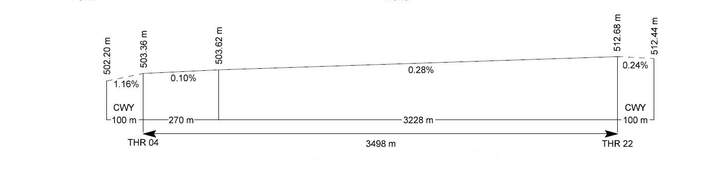
Profile
DECLARED DISTANCES
RWY |
TORA (m) |
TODA (m) |
ASDA (m) |
LDA (m) |
|---|---|---|---|---|
04 |
3498 |
3598 |
3498 |
3498 |
22 |
3498 |
3598 |
3498 |
3498 |
Remarks: None. |
||||
APPROACH AND RUNWAY LIGHTING
Runway |
04 |
|
Approach |
Precision CAT II/III 900. LIH. Threshold identification lights. |
|
PAPI (MEHT) |
3° (19.90 m/65 ft). |
|
Threshold |
Green, with wing bars. |
|
Touchdown zone |
900 m white. |
|
Runway centre line |
3498 m: 2598 m white + 600 m white and red + 300 m red. LIH. Distance between lights: 15 m. |
|
Runway edge |
3498 m: 2898 m white + 600 m yellow. LIH. Distance between lights: 50 m. |
|
Runway end |
Red. |
|
Stopway |
No. |
|
Remarks |
PAPI unfit for AN124 and AN225 aircraft. |
Runway |
22 |
|
Approach |
Simple 420 m LIH. Threshold identification lights. |
|
PAPI (MEHT) |
3° (22.23 m/73 ft). |
|
Threshold |
Green. |
|
Touchdown zone |
No. |
|
Runway centre line |
3498 m: 2598 m white + 600 m white and red + 300 m red. LIH. Distance between lights: 15 m. |
|
Runway edge |
3498 m: 2898 m white + 600 m yellow. LIH. Distance between lights: 50 m. |
|
Runway end |
Red. |
|
Stopway |
No. |
|
Remarks |
Rapid exit taxiway indicator lights TWY C1. PAPI unfit for AN124 and AN225 aircraft. |
OTHER LIGHTING, SECONDARY POWER SUPPLY
ABN/IBN |
No. |
|
WDI |
1 near THR 04, 1 near TWY B2, 1 near THR 22. LGTD. |
|
TWY lighting |
Centre line: A, B1, B2, C1, C2, D, E, T1, T2, T3, T4, T5, T6, TA6 and T7. Edge: E. |
|
Apron lighting |
Floodlighting poles (4 in Ramp 1 and 9 in Ramp 2). |
|
Secondary power supply |
Uninterrupted power system that provide a switchover time (light) for CAT II/III according to Annex 14. |
|
Remarks |
None. |
HELICOPTER LANDING AREA
Position |
|
|
Elevation |
|
|
Dimensions, surface, maximum weight, marking |
|
|
Direction |
No. |
|
Declared distances |
No. |
|
Lighting |
No. |
|
Remarks |
Apron lighting, see AD 2-LEVT PDC 1. Air taxiing: Maximum speed 37 km/h. |
(*)
PRKG |
ELEV (M) |
|---|---|
1H | 507.49 |
4 | 507.49 |
5 | 506.96 |
6 | 506.46 |
7 | 507.58 |
8 | 507.13 |
101 | 507.32 |
105 | 507.38 |
106 | 507.56 |
AIR TRAFFIC SERVICES AIRSPACE ATS AIRSPACE
Designation |
CTR VITORIA. |
|
Lateral limits |
Space within: 430112N 0023753W; 425935N 0023433W; 425502N 0022456W; 425014N 0022206W; 424646N 0022300W; 424554N 0022427W; 424155N 0023107W; 424547N 0024156W; 424327N 0024407W; 424120N 0024907W; 423621N 0025401W; 424016N 0030140W; 425017N 0025155W; 425208N 0025300W; 425523N 0025037W; 425803N 0024716W; 425910N 0024502W; 425913N 0024019W; 430112N 0023753W. |
|
Vertical limits |
SFC-6000 ft AMSL. |
|
Airspace class |
D. |
|
Unit Language |
VITORIA TWR. ES/EN. |
|
Transition altitude |
1850 m / 6000 ft. |
|
Hours of applicability |
- |
|
Remarks |
None. |
Designation |
ATZ VITORIA. |
|
Lateral limits |
Circle radius 8 km centred on ARP (1). |
|
Vertical limits |
SFC-3000 ft HGT (2). |
|
Airspace class |
D. |
|
Unit Language |
VITORIA TWR. ES/EN. |
|
Transition altitude |
- |
|
Hours of applicability |
- |
|
Remarks |
(1) Or the ground visibility, whichever is lower. (2) Or up to the cloud ceiling, whichever is lower. |
AIR TRAFFIC SERVICES COMMUNICATION FACILITIESATS COMMUNICATION FACILITIES
Service |
Call sign |
FREQ |
HR |
Remarks |
|---|---|---|---|---|
APP/TWR |
Vitoria TWR |
118.450 MHz |
HR ATS |
- |
121.500 MHz |
HR ATS |
EMERG |
||
121.805 C |
HR ATS |
GMC |
||
257.800 MHz |
HR ATS |
MIL |
||
243.000 MHz |
HR ATS |
EMERG |
||
ATIS |
Vitoria información |
119.355 C |
HR ATS |
- |
D-ATIS |
Vitoria información |
NIL |
HR ATS |
Provision of ATIS information via data link. |
RADIO NAVIGATION AND LANDING AIDSRADIO NAVIGATION & LANDING FACILITIES
Facility (VAR) |
ID |
FREQ |
HR |
Coordinates |
ELEV DME |
Remarks |
|---|---|---|---|---|---|---|
VOR (1ºE) |
VRA |
116.600 MHz |
H24 |
424354.8N 0025156.1W |
- |
|
DME |
VRA |
CH 113X |
H24 |
424354.8N 0025156.1W |
570 m |
R-259 possible signal loss at FL120 FM 40 NM. |
DVOR (1ºE) |
VFD |
112.900 MHz |
H24 |
425250.3N 0024327.7W |
- |
U/S BTN R-355/R-005 & R-220/R-315. |
DME |
VFD |
CH 76X |
H24 |
425249.8N 0024327.3W |
510 m |
- |
NDB (1ºE) |
VTA |
345.000 kHz |
H24 |
425541.1N 0024046.6W |
- |
035°: Possible signal oscillations greater than ±10° BTN 24 & 18 NM FM DME VRA. |
LOC 04 (1ºE) ILS CAT III |
VTO |
108.900 MHz |
H24 |
425352.3N 0024234.8W |
- |
035° MAG / 310 m FM THR 22. COV 17 NM ±35° FM RCL AVBL at 5500 ft AMSL or ABV. COV 25 NM ±10° FM RCL AVBL at 6000 ft AMSL or ABV. |
GP 04 |
- |
329.300 MHz |
H24 |
425218.1N 0024400.5W |
- |
3°; RDH 15.5 m; at 314 m FM THR 04 & 130 m FM RCL to the right in the direction of APCH. |
ILS/DME 04 |
VTO |
CH 26X |
H24 |
425218.1N 0024400.5W |
507 m |
REF DME THR 04. COV 17 NM AVBL BTN 13° to the right & 31° to the left FM RCL at 5500 ft AMSL or ABV. |
LOCAL AERODROME REGULATIONSLOCAL REGULATIONS
ILS CATEGORY II/III OPERATIONS
RWY 04, subject to service availability of the appropriate approach and landing aids, is suitable for carrying out CAT II/III operations by those air operators whose operational minima has been approved by the aeronautical civil authority.
The ILS Y RWY 04 manoeuvre is suitable for CAT III operations only with a missed approach slope of 3% or greater. The defining obstacles for the CAT II minima of this manoeuvre are:
OBST |
LAT |
LONG |
ELEV (ft) |
|
|---|---|---|---|---|
CAT II 3% |
LEVT-OBS-00911-000-2018 TORRE MEGA |
425307.2N |
0024341.3W |
1787.9 |
CAT II 2.5% |
RADAR METEOROLÓGICO KAPILDUI |
424557.5N |
0023216.0W |
4028.9 |
-
ILS Category II/III practice approaches:
Pilots seeking to practice CAT II/III precision approaches shall request the appropriate clearance from ATC well in advance.
Practice CAT II/III precision approaches will not be cleared when the RVR is less than 2000 m, or the same visibility value if the transmissometers are out of service, or the cloud ceiling is at or below 800 ft.
If ILS critical and/or sensitive areas are not protected, the crew shall be notified. Any other incident affecting the training operations shall also be reported.
STANDARD TAXIING PROCEDURES
-
Arriving aircraft
Aircraft shall report RWY vacated and TWY used for exit.
After vacating the RWY, if no taxiing instructions have been received, the aircraft will stop on the taxiway before entering the apron, and await taxiing instruction from the guidance vehicle.
-
Departing aircraft
Pilots will request clearance to start up engines to control tower.
When an aircraft is ready for taxiing, pilots shall request permission from the control tower before starting it.
-
Code letter D aircraft require carrying out an "oversteering" manoeuvre to correct the track:
Entry to / exit from PRKG 1, 2, 3, 4, 5, 6, 9, 10 and 11 on Ramp 2.
In all curves of the taxiing route assigned.
-
Code letter E aircraft are required to perform an "oversteer" manoeuvre to correct the manoeuvre:
In all curves of the taxiing route assigned.
Entry to / exit from PRKG 1A and 2A on Ramp 2.
Helicopters must carry out air taxiing, unless ATC advises differently, (see below HELICOPTER TAXIING PROCEDURE).
Collision avoidance with other aircraft or obstacles is the responsibility of the pilots when taxiing on the apron.
Power of engines on apron is limited to idle.
The back-track manoeuvre is not authorised at Vitoria Airport, except in winter contingency conditions of ice and snow and in special situations, as indicated in all cases by TWR Control.
OPERATING PROCEDURE FOR CODE LETTER E AIRCRAFT
- IN GENERAL
Aircraft with this code letter must perform an oversteer manoeuvre in all turns of the route.
Surface movements shall be carried out with TOAM guidance as indicated in the following points.
These aircraft are not allowed to use TWY: A, B1, B2, C1, TA6 and stretch E between E1 and E2.
- PARKING
Code letter E aircraft must park at the autonomous stands 1A and 2A on Ramp 2. PRKG 1A is incompatible with PRKG 1, 1H and 2; PRKG 2A is incompatible with PRKG 2 and 3. For entry/exit of both stands, aircraft must carry out a "turn with oversteer".
The TOAM will guide the aircraft both on arrival and departure, following the taxiing listed in the following "SURFACE MOVEMENT" section.
- GROUND MOVEMENT
- Arrivals:
RWY 04.- Vacate RWY via T1. The aircraft will wait for the support guidance vehicle for guiding, holding on T1 short of T2. The vehicle will guide it to the stand. Taxiing will be done through the parallel TWY T2, T3, T4 and T5, all the way to access gate D to Apron 2, TWY to access the apron towards the defined stand taxiing via E.
RWY 22.- Vacate RWY via T7. The aircraft will wait for the support guidance vehicle for guiding, holding on T7 short of T6. The vehicle will guide it to the stand. Taxiing will be done through the parallel TWY T6, all the way to access gate D to Apron 2, TWY to access the apron towards the defined stand taxiing via E.
The aircraft must perform an oversteer manoeuvre in all turns of the route.
- Departures:
RWY 04.- Starting from the defined stand, the vehicle will guide the aircraft to runway-holding position T7. Taxiing will take place exiting the apron through C2 until T5, taxiing via T5 and T6 and entering the RWY via T7 until THR 04.
RWY 22.- Starting from the defined stand, the vehicle will guide the aircraft to runway-holding position T1. Taxiing will take place exiting the apron through C2 until T4, taxiing via TWY T4, T3 and T2 and entering the RWY via T1 until THR 22.
The aircraft must perform an oversteer manoeuvre in all turns of the route.
- Arrivals:
OPERATING PROCEDURE FOR CODE LETTER F AIRCRAFT
-
IN GENERAL
Following the risk analysis performed, it has been shown that Vitoria Airport guarantees an adequate safety level for operation on Apron 2 of the following code letter F aircraft: A380-800, B747-800, AN-124 and AN-225.
During the operation of a code letter F aircraft, no taxiing will be allowed for any other aircraft throughout the movement area except on Apron 1. Taxiing of these aircraft will be performed at reduced speed, whenever possible with external motors off (if not possible, at idle speed), and with the other engines at idle speed.
Code letter F aircraft will receive guidance service for all manoeuvres.
PAPI of both thresholds are not suitable for the operation of AN124 and AN225 aircraft.
-
PARKING
The autonomous stand 2A on Ramp 2 has been allocated for code letter F aircraft, its use being incompatible with that of PRKG 2 and 3. The service roadway adjacent to said position will be part of PRKG 2A while these aircraft are parked on it and it will only be used to assist these aircraft.
For entry/exit to PRKG 2A on Ramp 2, aircraft must carry out a "turn with oversteer".
-
GROUND MOVEMENT
- Arrivals:
RWY 04.- Vacate RWY via T1. The aircraft will wait for the support guidance vehicle for guiding holding on T1 short of T2. The vehicle will guide it to the stand. Taxiing will be done through the parallel TWY T2, T3, T4 and T5, all the way to access gate D to Apron 2, TWY to access the apron towards the defined stand taxiing via E.
RWY 22.- Vacate RWY via T7. The aircraft will wait for the support guidance vehicle for guiding holding on T7 short of T6. The vehicle will guide it to the stand. Taxiing will be done through the parallel TWY T6, all the way to access gate D to Apron 2, TWY to access the apron towards the defined stand taxiing via E.
- Departures:
RWY 04.- Starting from the defined stand, the vehicle will guide the aircraft to the runway-holding position T7. Taxiing will take place exiting the apron via C2 until T5, taxiing via TWY T5 and T6 and entering the RWY via T7 until THR 04.
RWY 22.- Starting from the defined stand, the vehicle will guide the aircraft to the runway holding position T1. Taxiing will take place exiting the apron via C2 until T4, taxiing via TWY T3 and T2 and entering the RWY via T1 until THR 22.
The aircraft will need to make an "oversteer" manoeuvre at the same taxiing points marked in the Standard Taxiing Procedures for code letter E aircraft.
- Arrivals:
OPERATING PROCEDURE FOR CODE LETTER D AIRCRAFT WITH A WINGSPAN UP TO 38.05 m (B757-300) ON APRON 1
- IN GENERAL
Following the risk analysis performed it has been shown that Vitoria Airport guarantees an adequate safety level for operation on Apron 1 of code letter D aircraft with a wingspan up to B757-300 (38.05m).
During the operation of code letter D aircraft on Apron 1, no taxiing will be allowed for any other aircraft on Apron 1.
- PARKING
The autonomous stands 101A, 103A and 105A on Ramp 1 have been allocated for code letter D aircraft, their use being incompatible with that PRKG 101/102, 103/104 and 105/106, respectively. During arrival and departure operations to the stand, caution should be exercised to avoid the possible effects of the jet blast.
-
SURFACE MOVEMENT
- Arrivals:
- RWY 04.- Vacate RWY via A, B1 or T1, taxiing through the parallel TWY T2, T3, if appropriate, until the B2 access gate to Apron 1, TWY accessing Apron 1 towards the defined stand.
- RWY 22.- Vacate RWY via C1, B1 or T7, taxiing through the parallel TWY T6, T5, T4, if appropriate, until the B2 access gate to Apron 1, TWY accessing Apron 1 towards the defined stand.
- Departures:
- RWY 04.- Exit from the apron via B2, taxiing via TWY T4, T5 and T6 and entering the RWY via T7 until THR 04.
- RWY 22.- Exit from the apron via B2, taxiing via TWY T3 and T2 and entering the runway via T1 until THR 22.
- Arrivals:
HELICOPTER TAXIING PROCEDURE
IN GENERAL
At Vitoria Airport, operations with rotary wing aircraft take place. This activity is allowed during the airport's operational hours. Helicopters may operate under visual (VFR) and instrumental (IFR) flight rules.
The scope of this procedure are all helicopters with arrival/departure at Vitoria Airport. This procedure is also applicable to operations carried out by State aircraft, CNP, GUARDIA CIVIL and DGT (group B) when they are using the aerodrome public use facilities, including cases where they are carrying out emergency flights (operational).
All helicopters will conduct approaches, landings and take-offs in the same way as fixed wing aircraft, except for the following exceptions:
- Helicopters are allowed to leave RWY 04 via TWY C1.
In the event of low-visibility conditions, helicopters shall operate in accordance with the procedure described in item 22. Helicopter operations are not allowed for values of RVR<350 m. A FATO matching with the RWY and a TLOF matching with the FATO are defined. For air taxiing/skates, a TLOF is defined at the stand assigned to helicopters (1H).
TLOFS AND TOUCHDOWN AND LIFT OFF POINTS
Helicopters shall perform approaches and take-offs in the same way as fixed-wing aircraft, therefore they approach to RWY 04 or RWY 22 (based on weather conditions) as the designated FATO coincides with this runway.
There are two types of taxiing for helicopters: ground taxiing (wheel-type landing gear) or air taxiing (skid-type landing gear; wheel-type landing gear).
In case of ground taxiing helicopters, a FATO coinciding with the runway and a TLOF coinciding with the FATO are designated. For air taxiing, the TLOF is designated in the allocated helicopter stands (PRKG 101, 105 and 106 of APN 1 and PRKG 1H, 4, 5, 6, 7, and 8 of APN 2).
In the case of helicopters with wheel-type landing gear that decide to ground taxi, they land on the same runway by virtue of having an assigned TLOF coinciding with the FATO. Once on the ground, they taxi to the assigned stand in accordance with this procedure.
In the case of helicopters with skid-type landing gear or ones with wheel-type landing gear that decide to air taxi, the aircraft approaches the FATO and once hovering, air taxies to the TLOF of the assigned stands in accordance with this procedure. Departure operations are executed in the same way.
PARKING
There are nine helicopter stands that coincide with PRKG 1H, 4, 5, 6, 7 and 8 in APN 2 and PRKG 101, 105 and 106 in APN 1. These stands will be for helicopters with a maximum total length D = 23 m and 18.6 m rotor diameter.
Preferential assignment of stands will follow the following order of priority:
- PRKG 1H (R2)
- PRKG 7 (R2)
- PRKG 8 (R2)
- PRKG 106 (R1)
- PRKG 105 (R1)
- PRKG 101 (R1)
- PRKG 4 (R2)
- PRKG 5 (R2)
- PRKG 6 (R2)
STAND RESTRICTIONS
With regard to entry and exit operations at stands by means of autonomous ground rotation, the following restrictions apply to simultaneous operations:
- When a helicopter is exiting via autonomous ground taxiing at PRKG 101, a simultaneous operation at PRKG 102 shall not be permitted.
- When an aircraft is entering/exiting via autonomous ground taxiing at PRKG 105, a simultaneous operation at PRKG 106, 104 and 103A shall not be permitted. Furthermore, when entering via air taxiing, a simultaneous operation with PRKG 104 shall not be permitted.
- When an aircraft is entering/exiting via autonomous ground taxiing at PRKG 106, a simultaneous operation at PRKG 105 shall not be permitted. Furthermore, when entering via air taxiing, a simultaneous operation with PRKG 105 shall not be permitted.
There shall also be operational restrictions at stands, service roads, paths, ESA, etc.:
- At PRKG 101:
- When entry via air taxiing is performed, the service road to the left of the stand shall be restricted.
- When exiting by means of a hovering turn, the service road to the left of the stand and the equipment staging area shall be restricted.
- When exiting by means of autonomous ground turning, it is necessary to restrict pedestrian roads located in front of the stand.
- When a helicopter is exiting by means of a hovering turn at PRKG 105, there shall be no aircraft parked at PRKG 104 or 103A.
- When a helicopter is exiting by means of a hovering turn at PRKG 106, a simultaneous operation at PRKG 105 shall not be permitted.
- When a helicopter is exiting by means of a hovering turn at PRKG 7 and 8, the road to the left of both parking stands as well as the service road in front of PRKG 7 shall be restricted.
- When a helicopter is exiting by means of autonomous ground turning at PRKG 7, the service road in front of the stand shall be restricted.
On the other hand, when an aircraft is entering/exiting PRKG 7, no aircraft shall be parked at PRKG 8.
TAXIING ROUTES
As mentioned above, Vitoria Airport does not have a defined specific area for helicopters operations. Helicopters are treated as fixed wing aircraft and shall be cleared by ATC for take-off and landing on runways.
TWY enabled for helicopters are the same as those used by planes. There are no TWY exclusively for helicopters.
At Vitoria Airport no air taxiways are enabled outside those defined for taxiing.
Helicopters will be cleared to exit or enter via RWY 04/22, according to the indicated below. No helicopter arrival or departure operations other than those indicated in these proceedings shall be allowed.
For helicopter arrivals from both thresholds of RWY 04/22 that shall park on APN 2 (PRKG 1H, 4, 5, 6, 7 or 8), they shall vacate the runway preferably via exit TWY C1, where necessary for operational reasons, vacating may be made via other taxiways following fixed-wing aircraft markings. They shall then have the option of taxiing along TWY C2 towards TWY E or along TWY T5 and D towards TWY E. Finally, from TWY E they shall taxi to the assigned helicopter stand. When the operating helicopter is assigned PRKG 1H, the entry to the stand shall be made following the apron markings for that PRKG, with the stand and stand perimeter signs.
In the event that a stand other than PRKG 1H is assigned, the entry to the stand must be performed under the following conditions:
- PRKG 4, 5 and 6: entry to the stand shall be guided by the markings for fixed-wing aircraft, up to the appropriate horizontal marking in accordance with regulations is in place. The helicopter touchdown and lift off positioning shall, in any case, be guided with marshalling by the handling agent (or by the TOAM service, if necessary), with the helicopter remaining within the safety margins of the fixed-wing aircraft stand.
- PRKG 7 and 8: entry to the stand shall be guided by the markings for fixed-wing aircraft, until the appropriate horizontal marking in accordance with regulations is in place. The helicopter touchdown and lift off point shall be established using the fixed-wing aircraft stop bar as a visual reference in which the helicopter must stop, remaining within the safety margins of the fixed-wing aircraft stand.
The flight crews/occupants of helicopters that have been assigned stands on APN 2 shall leave the manoeuvring area via vehicles authorised to circulate on the apron or by using the pedestrian roads available. Under no circumstance shall they move freely in the rest of the manoeuvring area.
For helicopter arrivals from both thresholds of RWY 04/22 that shall park on APN 1 (PRKG 101, 105 or 106), they shall vacate the runway preferably via exit TWY B1, where necessary for operational reasons, vacating may be made via other taxiways following fixed-wing aircraft markings. They shall then taxi along TWY B2 towards TWY E, and then they shall taxi to the assigned helicopter stand.
- PRKG 101, 105 and 106: entry to the stand shall be guided by the markings for fixed-wing aircraft, up to the appropriate horizontal marking in accordance with regulations is in place. The helicopter touchdown and lift off positioning shall, in any case, be guided with marshalling by the handling agent (or by the TOAM service, if necessary), with the helicopter remaining within the safety margins of the fixed-wing aircraft stand. Additionally, the turn signal for fixed-wing aircraft shall be available as a visual reference for the touchdown and lift off positioning of the helicopter.
In the event that an APN 1 stand is assigned, entry to the stand must be performed under the following conditions, with no exceptions:
The flight crews/occupants of helicopters that have been assigned parking stands on APN 1 shall leave the manoeuvring area via vehicles authorised to circulate on the apron or by using the pedestrian roads available adjacent to PRKG 101, 105 and 106. Under no circumstance shall they move freely in the rest of the manoeuvring area.
DEPARTURES TO RWY 04/22 FROM APN 2
The preferred routes to be followed via taxiway to each threshold shall be as follows:
- If parked at PRKG 1H and departing via RWY 22: head to TWY C2, then taxi to the intermediate holding position on that TWY and then along TWY T4, T3, T2 and T1 up to the threshold 22.
- If parked at PRKG 1H and departing via RWY 04; head to TWY C2, then taxi to the intermediate holding position on that TWY and then along TWY T5, T6, T7 up to the threshold 04.
- If parked at PRKG 4, 5, or 6 and departing via RWY 22, head to TWY C2, then taxi to the intermediate holding position on that TWY and then along TWY T4, T3, T2 and T1 up to the threshold 22.
- If parked at PRKG 4, 5, or 6 and departing via RWY 04, head to TWY D, then taxi to the intermediate holding position on that TWY and then along TWY T6 and T7 up to the threshold 04.
- If parked at PRKG 7 or 8 and departing via RWY 22, head to TWY D, then taxi to the intermediate holding position on that TWY and then along TWY T5, T4, T3, T2 and T1 up to the threshold 22.
- If parked at PRKG 7 or 8 and departing via RWY 04, head to TWY D, then taxi to the intermediate holding position on that TWY and then along TWY T6 and T7 up to the threshold 04.
DEPARTURES TO RWY 04/22 FROM APN 1
The preferred routes to be followed via taxiway to each threshold shall be as follows:
- Departing via RWY 22: head to TWY B2, then taxi to the intermediate holding position on that TWY and then along TWY T3, T2 and T1 to the threshold 22.
- Departing via RWY 04: head to TWY B2, then taxi to the intermediate holding position on that TWY and then along TWY T4, T5, T6, T7 to the threshold 04.
TAXIING LIMITATIONS
As for infrastructure, there are no taxiing limitations. Any helicopter can make use of any existing taxiways regardless of their ground run or air performance.
HANGAR ENTRY AND EXIT
Aircraft will enter and exit the hangars from the 3 taxiways adjacent to the general aviation parking stands as given below:
- Entry to/exit from Hangar 1 via the taxiway north of PRKG 112-116.
- Entry to/exit from Hangars 2 and 3 via the taxiway between the 2 rows of general aviation PRKG 107-111 and 112-116.
- Entry to/exit from Hangar 4 via the taxiway between PRKG 106 and the row of general aviation PRKG 107-111.
These manoeuvres will be performed with the engines off, and the aircraft towed by tractor or in the case of small aircraft, pushed. When entering, engines will be switched off at the end of the taxiway centre line, the point at which towing begins; when exiting, the aircraft will be towed to the same point, where the towing ends and the engines are started up.
Roadways crossed during the hangar entry/exit manoeuvres are signposted with STOP AIRPLANE PASSING signs, so that the manoeuvres may be carried out safely.
HANGAR ENTRY AND EXIT FOR AIRCRAFT WITH A WINGSPAN GREATER THAN 12 M AND FOR HELICOPTERS
In the event that aircraft with a wingspan greater than 12 m or helicopters must enter or exit the hangars, the procedure will be as follows:
- Fixed-wing aircraft with a wingspan greater than 12 m: aircraft with a maximum wingspan of 17.5 m are permitted.
- Entry to hangars: the aircraft will taxi under its own power to the MAX SPAN 12 m marking, where it will stop and shut down engines. Next, it will request TWR for push-back clearance and once cleared, it will be towed or pushed, always following the taxiway centre line markings. All post-flight checks required by the aircraft must be carried out once it is in the hangar.
- When proceeding to Hangar 1, the aircraft will use the taxiway between the row of PRKG 112-116 and the perimeter roadway. The following restrictions must be taken into account:
- No vehicles may circulate on the adjacent roadway during the entry manoeuvre.
- PRKG 107 and PRKG 112 to 116 must be empty, without parked aircraft, vehicles, persons and objects.
- Entry to hangars: the aircraft will taxi under its own power to the MAX SPAN 12 m marking, where it will stop and shut down engines. Next, it will request TWR for push-back clearance and once cleared, it will be towed or pushed, always following the taxiway centre line markings. All post-flight checks required by the aircraft must be carried out once it is in the hangar.
- When proceeding to Hangars 2 or 3, the aircraft will use the taxiway between the row of PRKG 107-111 and the row of PRKG 112-116 (width of taxiway: 20 m). The following restrictions must be taken into account:
- PRKG 107-116 must be empty, without parked aircraft, vehicles, persons and objects.
- When proceeding to Hangar 4, the aircraft will use the taxiway between PRKG 106 and the row of PRKG 107-111 (width of taxiway: 24 m). The following restrictions must be taken into account:
- The equipment staging area of PRKG 106 must be empty of people, objects and vehicles.
- Exit from the hangars: similar to the entry, taking into account the same restrictions. The following should also be taken into account:
- All pre-flight checks required by the aircraft must be carried out inside the hangar, before the start of towing or pushing.
- Push-back clearance must be obtained from TWR prior to towing or pushing the aircraft from the hangar to the MAX SPAN 12 m marking.
- Once the MAX SPAN 12 m marking is reached and the area has been checked, TWR must be notified that the push-back manoeuvre is completed, and start-up and taxiing clearance requested. Once clearance is obtained, the aircraft may start its engines and taxi under its own power.
- Helicopters: Helicopters with rotor diameter ≤ 17.5 m are permitted.
- Entry to hangars: the helicopter will taxi under its own power to the MAX SPAN 12 m marking, where it will stop and shut down engines. Next, it will request TWR for push-back clearance and once cleared, it will be towed or pushed, always following the markings of the taxiway centre line. All post-flight checks required by the aircraft must be carried out once it is in the hangar.
In the absence of TLOF marking before the MAX SPAN 12 m marking, helicopters air taxiing to that point will use the taxiway centre line as a longitudinal guide and the MAX SPAN 12 m marking as a transversal guide, as visual references.
- When proceeding to Hangar 1, the helicopter will use the taxiway between the row of PRKG 112-116 and the perimeter roadway. The following restrictions must be taken into account:
- No vehicles may circulate on the adjacent roadway during the entry manoeuvre.
- In case of rotor diameter over 12 m (and always ≤ 17.5 m), PRKG 107 and PRKG 112 to 116 must be empty, without parked aircraft, vehicles, persons and objects.
- When proceeding to Hangars 2 or 3, the helicopter will use the taxiway between the row of PRKG 107-111 and the row of PRKG 112-116 (width of taxiway: 20 m). The following restrictions must be taken into account:
- When entering Hangar 2, PRKG 115 and 116 must be empty.
- When entering Hangar 3, PRKG 110 and 111 must be empty.
- In case of rotor diameter over 12 m (and always ≤ 17.5 m) and proceeding to Hangar 2 or 3, PRKG 107 to 116 must be empty, without parked aircraft, vehicles, persons and objects.
- When proceeding to Hangar 4, the helicopter will use the taxiway between PRKG 106 and the row of PRKG 107-111 (width of taxiway: 24 m). The following restrictions must be taken into account:
- The equipment staging area of PRKG 106 must be empty of people, objects and vehicles.
In all 3 cases, once the end of the centre line marking is reached, the aircraft will proceed as described in the section HANGAR ENTRY AND EXIT. Once the helicopter has been towed or pushed, the personnel of the AAT/Operating Company that has towed or pushed the helicopter will conduct a check of the area through which the helicopter has been towed, including the vehicle roadway crossing, in order to ensure that the manoeuvre has not damaged the pavement or generated FOD; If there is any damage, they will inform the Airport Operations Coordination Centre (CEOPS) by telephone and CEOPS may, if it deems it necessary, request the RFFS to conduct an extraordinary check of the area. After towing and checking the area, TWR will be informed that the push-back manoeuvre is completed.
- Exit from the hangars: similar to the entry, taking into account the same restrictions. Only the following points must be taken into account:
- All pre-flight checks required by the aircraft must be carried out inside the hangar, before the start of towing or pushing.
- Push-back clearance must be obtained from TWR prior to towing or pushing the aircraft from the hangar to the MAX SPAN 12 m marking.
- Once the MAX SPAN 12 m marking is reached and the area has been checked, TWR must be notified that the push-back manoeuvre is completed, and start-up and taxiing clearance requested. Once clearance is obtained, the aircraft may start its engines and taxi under its own power.
- Towing helicopters on the vehicle roadway: helicopters with a maximum width of 3 metres (including rotors) and final destination one of the hangars (1, 2, 3 or 4) or a location outside the Airport Air Side, which may be towed on a service road lane (lane width 3.5 m) without exceeding the lane limits due to their small size, may be towed following the Apron Safety Guidelines (NSP), and the towing personnel will ensure compliance with all safety measures applicable to the hangar and/or stand exit and entry. To do so, the helicopter will position itself at one of the stands suitable for helicopters on APN 1 (PRKG 101, 105 or 106), as notified by TWR after the stand is assigned by CEOPS, and then towed via the roadway to the appropriate hangar or to leave the air side. Once the stand is vacated, both TWR and CEOPS must be notified so they are aware that the stand is available.
When the helicopter is exiting the hangar, or arriving from outside the airport, the procedure will be the same: it will be towed via the roadway to PRKG 101, 105 or 106.
In all 3 cases, once the end of the centre line marking is reached, the aircraft will proceed as described in the section HANGAR ENTRY AND EXIT. Once the aircraft has been towed or pushed, the personnel of the AAT/Operating Company that has towed or pushed the aircraft will check the area through which the aircraft has been towed, including the vehicle roadway crossing, in order to ensure that the manoeuvre has not damaged the pavement or generated FOD. If there is any damage, they shall inform the Airport Operations Coordination Centre (CEOPS) by telephone and CEOPS may, if deemed necessary, request RFFS to conduct an extraordinary check of the area. After towing and checking the area, TWR will be informed that the push-back manoeuvre is completed.
DE-ICING AND OPERATING PROCEDURES IN WINTER CONDITIONS
The airport has de-icing and operating procedures in winter conditions. For information on these, please contact the CEOPS Office:
- TEL: +34-945 163 518
- e-mail: VITCEOPS@aena.es
NIGHT VISUAL OPERATIONS (VFR-N)
VFR-N flights are permitted.
OPERATIONAL SAFETY REPORTS
Pilots/the operator shall report to the airport as soon as possible about any accidents, incidents, occurrences or events which may have a potential operational impact and in which they have been involved or witnessed.
The aim of these reports is to compile information in order to improve operational safety, regardless of the compulsory report of the occurrence to the appropriate aeronautical authority.
Data may be sent in any format, including at least the following information:
- Date and time.
- Site.
- Parties involved (data used to identify vehicles, aircraft … involved).
- Companies involved.
- Description of the facts.
- Any other data considered relevant (e.g. lighting conditions, weather, phase of the operation such as take-off/landing/stopover, pavement conditions…).
The contact airport e-mail address for receiving operational safety reports is the following: VITSeguridadOperacional@aena.es
In addition to notifying the airport by means of the indicated system, it is necessary to send at least basic data of the accident, incident, occurrence or event to the air traffic control service provider (ATC).
On the specific instance of safety reports related with the air traffic control service provider (manoeuvring area, flight phases and ATS airspace) these may be sent to the e-mail address: lecm.safety@enaire.es
AIRPORT EMERGENCY PLAN
See AD 1.1.
NOISE ABATEMENT PROCEDURES
MOTOR TESTS
- ENGINE IDLING TEST
These tests may be conducted, with CEOPS authorisation and in coordination with the TWR, at any time during operational hours, on all stands except PRKG 101 and 101A.
In any case, these tests shall not be authorised when pedestrian boarding and debarking, handling activities, refuelling or any other activity that involves the movement of people and/or vehicles are underway or will be underway at the adjacent stands.
- POWER TESTS
The test may be conducted, with CEOPS authorisation and in coordination with the TWR, at an intermediate holding position on TA6, at an intermediate holding point on T6, or at PRKG 12 on Apron 2, depending on availability at the time and based on the code letter of the aircraft to conduct the test (PRKG 12, code letter D; TWY TA6, code letter D; TWY T6, code letter E). The test shall not be authorised at PRKG 12 when pedestrian boarding and debarking, handling activities, refuelling or any other activity that involves the movement of people and/or vehicles are underway or will be under way at PRKG 11.
In any case, the orientation of the aircraft shall be coordinated between TWR-CEOPS and the requesting Air Carrier.
FLIGHT PROCEDURES
LOW VISIBILITY PROCEDURES (LVP)
IN GENERAL
RWY 04 is equipped with ILS CAT II/III, and CAT III approaches are cleared.
Reduced visibility take-offs are cleared in RWY 04/22.
Low Visibility Procedures (LVP) will be applied when these operations are carried out. When this is the case, pilots will be notified via ATIS or RTF. In any case, LVP will be active when RVR is equal to or less than 1700 m at any RVR gauge (or VIS equal to or less than 1700 m in case of failure of all gauges) or the cloud ceiling is below 600 ft.
GROUND MOVEMENT
ATC may use lighted intermediate holding positions as well as stop bars as clearance limits in order to manage ground movements.
The following measures will be taken:
- Aircraft requiring guidance after landing or aborted take-off shall vacate the runway and stop once established on the taxiway and having cleared the ILS sensitive area, unless otherwise stated by the pilot or ATC.
- Taxiways:
- The use of TWY TA6 is prohibited.
- With RVR less than 550 m (unless cleared by ATC):
- RWY 04 in use: it is forbidden to vacate the RWY by TWY B1.
- RWY 22 in use: it is forbidden to vacate the RWY by TWY B1 and TWY C1.
- Aircraft stands: all entrances and exits to and from all aircraft stands shall be with guidance vehicle, when the RVR is under 550 m. This is with the exception of PRKG 101.
- Helicopters shall operate like any fixed-wing aircraft and shall be guided by guidance vehicle, when the RVR is under 550m.
Departures
- In order to optimise the traffic sequence, crews shall not request start-up, push-back or taxiing clearances when weather conditions are below their operational minima.
- When requesting start-up clearance, the parking stand where the aircraft is located must be reported to ATC.
-
When the RVR is less than 200 m or the taxiway centre line lights are out of service and the RVR is under 550 m, taxiing aircraft shall be guided by guidance vehicle, up to:
- RWY 04 in use: TWY T6-T7 intersection; where the FOLLOW ME lights shall be switched off and TWY T vacated via the service road until the vehicle shall turn off the YES lights and leave TWY T along the service road to the vehicle waiting point. The aircraft will continue taxiing until TWY T7.
- RWY 22 in use:TWY T1-T2 intersection; where the FOLLOW ME lights shall be switched off and TWY T vacated via the service road until the vehicle will turn off the YES lights and leave TWY T along the service road to the vehicle waiting point. The aircraft will continue taxiing until TWY T1.
- If the aircraft must return to the apron, the crew shall inform ATC and await further instructions for taxiing with guidance vehicle.
- Preferred taxiing routes for departures:
| EXIT ROUTES FROM APRON 1 AND APRON 2 TO THE RUNWAY | ||
|---|---|---|
| TO RWY | FROM APRON 1 | FROM APRON 2 |
| 04 | B2, T4, T5, T6, T7 | C2, T5, T6, T7 or D, T6, T7 |
| 22 | B2, T3, T2, T1 | D, T5, T4, T3, T2, T1 or C2, T4, T3, T2, T1 |
Arrivals
- When vacating the RWY, pilots shall report the ILS sensitive area (LSA) and exit taxiway used. The ILS sensitive area ends when the exit TWY centre line lights have all turned green, instead of green and yellow.
- Aircraft that have landed shall vacate the runway in use and stop if they do not receive taxiing instructions. Once cleared, they shall proceed to APRON 1 or APRON 2 via one of the taxiways assigned by ATC.
| RWY | Exit TWY | Route to APRON 1 | Route to APRON 2 |
|---|---|---|---|
| 04 | T1 | T2, T3, B2 | T2, T3, T4, C2 or T2, T3, T4, T5, D |
| A | T3, B2 | T3, T4, C2 or T3, T4, T5, D | |
| B1 | B2 | T4, C2 or T4, T5, D |
- When the RVR is less than 200 m or the taxiway centre line lights are out of service and the RVR is under 550 m, taxiing aircraft shall be guided by guidance vehicle.
- Where appropriate, they shall inform ATC when they have "Guidance vehicle in sight". They shall not commence guided taxiing until they receive the appropriate ATC clearance to taxi and follow the guidance vehicle.
ABNORMAL SITUATIONS IN THE MANOEUVRING AREA
Communications failure
- Departures
Aircraft shall continue taxiing until the limit of ATC clearance and await the arrival of assistance.
- Arrivals
- If the aircraft has just landed, it shall maintain its position when vacating the ILS sensitive area and await the arrival of an assistance vehicle
- If the aircraft has already received taxiing clearance from ATC, it shall continue along the designated route to the limit of the ATC clearance, exercising extreme caution, where it shall maintain its position and await the arrival of an assistance vehicle.
Position on the manoeuvring area uncertain
- Except as provided in the paragraph below, if a pilot is in doubt as to the position of the aircraft in relation to the manoeuvring area, he/she shall immediately stop the aircraft and notify ATC of this fact (including the last known position).
- In situations where the pilot is uncertain as to the position of the aircraft in relation to the manoeuvring area, but recognises that the aircraft is on a runway, the pilot shall immediately notify ATC (mentioning the last known position), evacuate the runway as soon as possible, if able to locate a suitable nearby taxiway, unless otherwise instructed by ATC, and then stop the aircraft.
- In the event that ATC becomes aware that an aircraft or vehicle has lost its position on the manoeuvring area, or is unsure of its position, appropriate action shall be taken immediately to safeguard operations and to assist the aircraft or vehicle in question to determine its position.
Loss of visual contact between mobile craft
- In the event that an aircraft loses visual contact with another aircraft or with a vehicle with which it maintains separation, ATC shall be informed immediately and the aircraft shall be stopped. ATC will take any measures it deems appropriate.
Aircraft failure
- ATC shall be notified of the situation and the aircraft shall wait for assistance to arrive. If on a runway, when able and unless otherwise instructed by ATC, measures to evacuate shall be adopted.
CONTINUOUS DESCENT OPERATIONS
Depending on traffic situation, and if no need for interrupting the descent is foreseen, aircraft will be cleared to proceed to a standard arrival (STAR), or by means of a "direct to" clearance to an intermediate fix of the STAR, to the IAF, to an intermediate approach fix or to the IF, to an appropriate altitude of the instrumental procedure (IAC), in order to allow a continuous descent operation.
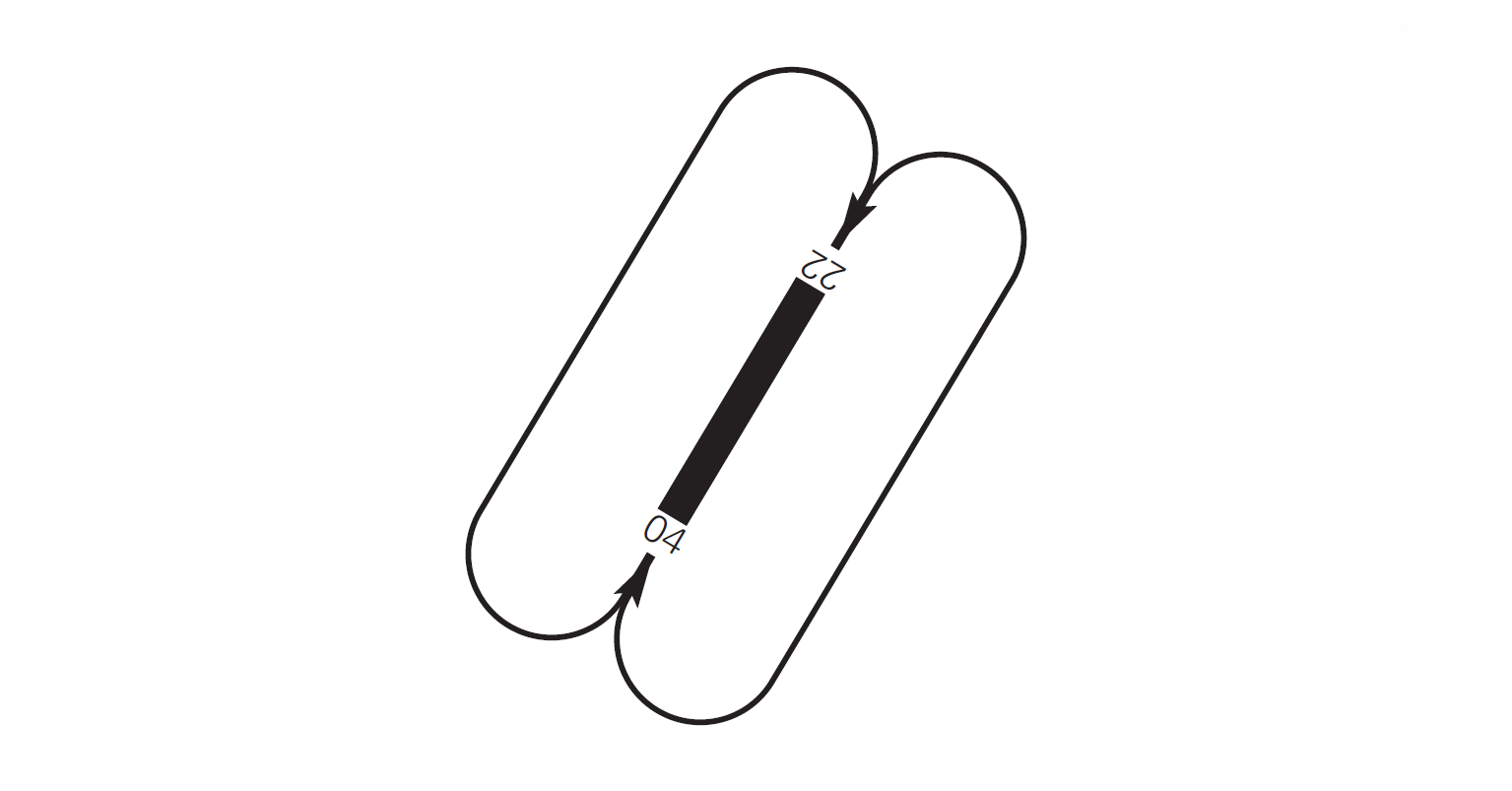
AD TRAFFIC CIRCUIT
ADDITIONAL INFORMATION
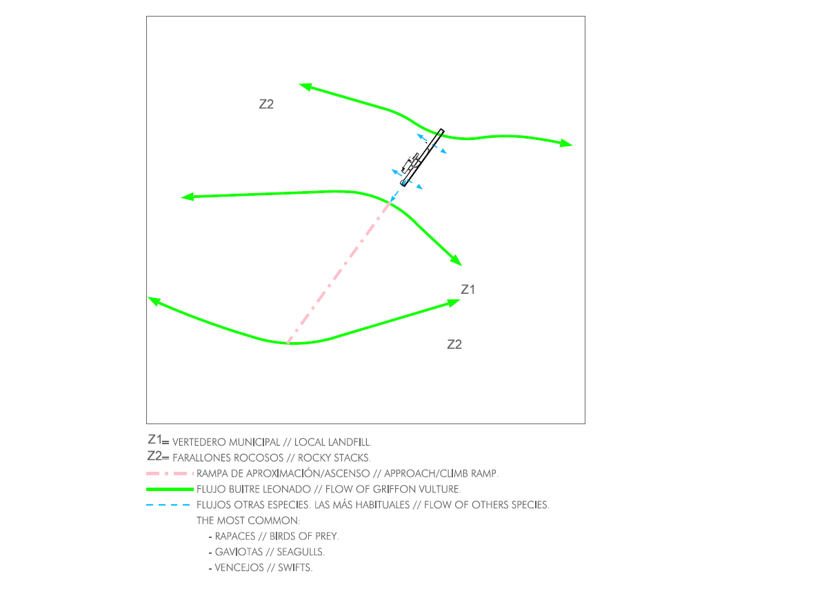
Caution due to the occasional presence of birds. Possible presence of vultures in approach.
When the wind speed exceeds 130 km/h, operations will be suspended at the airport.
BIRD CONCENTRATION AREAS
AERONAUTICAL CHARTS RELATED TO AN AERODROMECHARTS RELATED TO THE AERODROME
The list of charts related to the aerodrome can be found on the link below:
VISUAL SEGMENT SURFACE (VSS) PENETRATION
IAC 8 RNP Y RWY 04: LNAV, LNAV/VNAV.
IAC 9 VOR RWY 22: Directed approach.
IAC 10 RNP Z RWY 22 (LPV ONLY): LPV.
IAC 11 RNP Y RWY 22: LNAV, LNAV/VNAV.