LEST AD 2 AERODROME DATA
AERODROME LOCATION INDICATOR AND NAME
LEST - SANTIAGO/Rosalía de Castro
AERODROME GEOGRAPHICAL AND ADMINISTRATIVE DATA
| ARP | 425347N 0082455W. See AD 2-LEST ADC. | |
| Distance and direction from the city | 10 km NE. | |
| Elevation | 369 m / 1211 ft. | |
| Geoid undulation | 49.54 m ± 0.05 m (1). | |
| Reference temperature | 25°C. | |
| Low average temperature | 7ºC. | |
| Magnetic variation | 1ºW (2025). | |
| Annual change | 10.5'E. | |
| AD administration |
CIV: Aena.
MIL: Ejército del Aire y del Espacio. |
|
| Address |
CIV: Aeropuerto de SANTIAGO/Rosalía de Castro, Lavacolla, s/n. 15820 Santiago de Compostela (A Coruña).
MIL: Aérodromo militar de Santiago, Lavacolla, s/n. 15820 Santiago de Compostela (A Coruña). |
|
| TEL |
CIV: +34-981 547 561/0/3
MIL: +34-981 897 402 |
|
| FAX |
CIV: +34-981 547 564
MIL: +34-981 897 410 |
|
| AFTN | LEST | |
|
CIV:
listascqcoordinacion@aena.es
MIL: amsan@ea.mde.es |
||
| Approved traffic | IFR/VFR. | |
| Remarks |
(1) For all AD points.
SITA: SCQOPYA. |
OPERATIONAL HOURS
| Airport |
CIV: H24. I: MON-THU: 0700-1330, FRI: 0700-1300. |
|
| Customs and Immigration | H24. | |
| Health and Sanitation | See item 5 and GEN 1.4. | |
| AIS/ARO/OPV | H24 (3) | |
| MET briefing | H24. | |
| ATS | H24. | |
| Fuelling | (4). | |
| Handling | H24. | |
| Security | H24. | |
| De-icing | H24. | |
| Remarks |
(1) Exceptions: - Spanish military aircraft acting under specific orders and instructions from the corresponding Command. - NATO Integrated Air and Missile Defence System (NATINAMDS). (2) Other hours on request. It is compulsory for foreign state/military aircraft to request PPR at least 72 hours in advance to:
Centralised AIO Office - International NOTAM Office
|
HANDLING SERVICES AND FACILITIES
| Cargo facilities | No limitations. | |
| Fuel types | 100LL, JET A-1. | |
| Oil types | AEROSHELL 100. | |
| Refuelling capacity | No limitations. | |
| De-Icing facilities | Service provided by handling operator with hot water and glycol equipment. See item 20: Local regulation, Aircraft de-icing. | |
| Hangar space | No. | |
| Repair facilities | No. | |
| Remarks |
MIL: GPU: Unit of AC (up to 100 KVA) and CC (up to a peak of 2500 A / permanent 1000 A).
It is mandatory to have a handling agent for all operations, non-commercial operations included, except for aircraft parked on the military apron, rescue flights , State flights and flights providing a service to the Comunidades Autonomas and other local authorities whenever they are providing non-commercial public services. In arrival operations, passengers and crews must wait for their handling agent.
SOUTH
Ramp agents may attend both commercial aviation and general aviation.
Ramp agents (General Aviation):
SANTIAGO (LEST/SCQ)
Handling agent (General aviation):
|
PASSENGER FACILITIES
| Hotels | No. | |
| Restaurant | Yes. | |
| Transportation | CIV:Buses, taxis and hire cars. MIL: Crew minibus O/R. | |
| Medical facilities | First aid. (1) | |
| Bank/Post Office | Cash dispenser / Post box. | |
| Tourist information | Yes. | |
| Remarks |
(1) Request for availability to the Airport Coordination Center.
|
RESCUE AND FIREFIGHTING SERVICES
| Fire category | 7. (1) | |
| Rescue equipment | In accordance with the fire category published. | |
| Removal of disabled aircraft | Tractors and push-back bars belonging to the handling companies. Lifting bags up to 31 TM, debogging equipment with capacity up to 40 TM, aircraft hoisting equipment with capacity up to 30 TM. Service commitment from local companies that are able to handle loads up to 500 TM. (2) | |
| Remarks |
Operational objective of response time up to RWY 17/35 end less than 2 MIN.
|
RUNWAY SURFACE CONDITION ASSESSMENT AND REPORTING, AND SNOW PLAN
| Types of clearing equipment | One snowplough vehicle with 4000 mm scoop and 5 m3. urea spreader. | |
| Clearance priorities | Runway, TWY E3, apron P4, apron taxiways and stands in contact with the terminal and rest f the movement área. | |
| Use of material for movement area surface treatment | Potassium acetate (KAC) and urea (UREA). | |
| Specially prepared winter runways | Not applicable. | |
| Remarks |
Period of application of snow plan: 01-NOV to 31-MAR. Runway surface condition assessment and reporting in accordance with the Global Reporting Format (GRF) methodology described in AD 1.2.2.
Aerodrome in service during all seasons of the year. |
APRONS, TAXIWAYS AND CHECK LOCATIONS/POSITIONS DATA
| Apron |
Surface: Concrete and asphalt.
Strength: P1: PCN 74/R/A/W/T P2: PCN 44/F/B/W/T P3: PCN 69/R/A/W/T P4: PCN 46/R/A/W/T |
|
| Taxiways |
Width: 23 m, except T (BTN E2 & E3): 46 m.
Surface: Asphalt. Strength: D1: PCN 74/R/A/W/T. D2: PCN 52/F/B/W/T. D3: PCN 115/F/A/W/T. D4: PCN 115/F/A/W/T. E1: PCN 74/F/A/W/T. E2: PCN 92/F/A/W/T. E3: PCN 92/F/A/W/T. E4: PCN 56/F/B/W/T. R: PCN 115/F/A/W/T. T (BTN E1 & D1): PCN 135/F/A/W/T. T (BTN D1 & E2): PCN 52/F/B/W/T. T (BTN E2 & D3): PCN 44/F/A/W/T. T (BTN D3 & E4): PCN 56/F/B/W/T. Y: PCN 32/R/A/W/T. Z: PCN 52/F/B/W/T. |
|
| Check locations |
Altimeter: Apron P1: 361 m / 1184 ft. Apron P3: 365 m / 1196 ft. Apron P4: 368 m / 1207 ft.
VOR: No. INS: See AD 2-LEST PDC. |
|
| Remarks | None. |
SURFACE MOVEMENT GUIDANCE AND CONTROL SYSTEM AND MARKINGS
| Taxiing guidance system | Runway-holding positions, stop bars, stands, intermediate holding positions, pre-threshold area, LGTD mandatory instruction and information signs, runway guard lights, visual docking guidance systems at parking stands. | |
| RWY markings | Displaced thresholds, designators, centre line, touchdown zone, aiming point and side stripe. | |
| TWY markings | Centre line, edge. E1, E2, E3, E4, D1, D2, D3, D4, R, T and Y: edge reflective markers. | |
| Remarks | Apron markings by means of reflective markers. |
AERODROME OBSTACLES
| Obstacles in Approach, Take-Off Climb, Conical, Inner Horizontal, Transitional, Inner Transitional and Balked Landing Surfaces established in ICAO Annex 14; and the areas 2A and 3 established in ICAO Annex 15. Those penetrating these surfaces are identified in the CSV file as “Relevante_Relevant = Si/Yes”. | See Item 10 and Data Set. | |
| Remarks | See AD 2-LEST AOC. |
METEOROLOGICAL INFORMATION PROVIDED
| MET office | Santiago EMAe. | |
| HR | H24. | |
| METAR | Half-hourly. | |
| TAF | 24HR. | |
| TREND | Yes. | |
| Briefing | In person and by telephone. | |
| Flight documentation/Language | Charts and plain language / Spanish. | |
| Charts | Forecast significant, wind and temperature at altitude maps. | |
| Supplementary equipment | Cloud and lightning image and radar information display. | |
| ATS unit served | TWR, APP. | |
| Additional information |
Santander OMAe (LESD): H24
Santiago EMAe: H24
|
|
| Remarks | Aerodrome climatological summary available. Aerodrome warnings available. There is a meteorological station sited at 4253N 00831W, near the AD area, which launches observation balloons weekly, on Tuesdays from 0630 to 0745. See ENR 5.3. Aerodrome MET guide available |
RUNWAY PHYSICAL CHARACTERISTICS
| RWY | Direction | DIM (m) | THR PSN | THR/TDZ ELEV | SWY (m) | CWY (m) | Strip (m) | OFZ | RESA (m) |
RWY/SWY SFC
PCN |
|---|---|---|---|---|---|---|---|---|---|---|
| 17 (1) (2) |
166.15° GEO
167° MAG |
3140 x 45 |
425438.71N
0082511.92W |
THR: 356.6 m / 1170 ft
TDZ: 364.0 m / 1194 ft |
No | 120 x 150 | 3260 x 280 (5) | Sí | 150 x 90 (6) |
RWY: ASPH (7)
SWY: No |
| 35 (3) (4) |
346.16° GEO
347° MAG |
3170 x 45 |
425306.49N
0082441.00W |
THR: 365.7 m / 1200 ft
TDZ: 369.1 m / 1211 ft |
No | 90 x 150 | 3290 x 280 (5) | No | 115 x 90 (6) |
RWY: ASPH (7)
SWY: No |
|
Remarks: (1) DTHR 17 120 m. Coordinates of the beginning of the take-off run: 425442.47N 0082513.18W. |
||||||||||
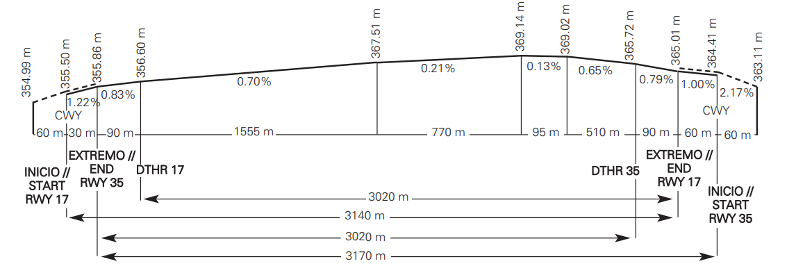
Profile:
DECLARED DISTANCES
| RWY | TORA (m) | TODA (m) | ASDA (m) | LDA (m) |
|---|---|---|---|---|
| 17 (1) (2) | 3140 | 3260 | 3140 | 3020 |
| 35 (3) (4) | 3170 | 3260 | 3170 | 3020 |
| 17 INT E2 | 1838 | 1958 | 1838 | — |
| 17 INT E3 | 1554 | 1674 | 1554 | — |
| 35 INT E2 | 1294 | 1384 | 1294 | — |
| 35 INT E3 | 1578 | 1668 | 1578 | — |
|
Remarks: (1) DTHR 17 120 m. Coordinates of the beginning of the take-off run: 425442.47N 0082513.18W. |
||||
APPROACH AND RUNWAY LIGHTING
| Runway | 17 | |
| Approach | Precision CAT II/III, 900 m LIH. | |
| PAPI (MEHT) | 3° (15.66 m / 51 ft). (1) | |
| Threshold | Green with wing bars. (3) | |
| Touchdown zone | 900 m. | |
| Runway centre line | 3080 m: 2180 m white + 600 m red/white + 300 m red. LIH. Distance between lights: 15 m. | |
| Runway edge | 3200 m: 120 m red + 2480 m white + 600 m yellow. LIH. Distance between lights: 50 m. | |
| Runway end | Red. (3) | |
| Stopway | No. | |
| Remarks |
(1)PAPI not available for aircraft of type B747 and A333.
(3) Threshold and end LED lighting. |
| Runway | 35 | |
| Approach |
Precision CAT I, 420 m LIH.
Threshold identification lights. |
|
| PAPI (MEHT) | 3° (16.97 m / 56 ft). (2) | |
| Threshold | Green. (3) | |
| Touchdown zone | No. | |
| Runway centre line |
3050 m: 2150 m white + 600 m red/white + 300 m red. LIH.
Distance between lights: 15 m. |
|
| Runway edge | 3200 m: 150 m red + 2450 m white + 600 m yellow. LIH. Distance between lights: 50 m. | |
| Runway end | Red.(3) | |
| Stopway | No. | |
| Remarks |
(2) PAPI not available for aircraft of type B747.
(3) Threshold and end LED lighting. |
OTHER LIGHTING, SECONDARY POWER SUPPLY
| ABN/IBN | No. | |
| WDI | 1 near DTHR 17 and 1 near DTHR 35. LGTD | |
| TWY lighting | E1, E2 E3, E4, D1, D2, D3, D4, R, T and Y: Centre line. (1) | |
| Apron lighting | 14 floodlighting poles. (2) | |
| Secondary power supply | Visual aid systems with uninterruptible power supply (UPS + Continuity Group) with a switch-over (light) time of 0 seconds, supported by generator sets with a maximum response time of 15 seconds. | |
| Remarks |
(1) LED lighting in runway holding positions in TWY E1 and E2, and in TWY D1, D2 and T centre lines.
(2) All the aprons (P1, P2, P3 and P4) have lighting available by means of floodlighting poles. |
HELICOPTER LANDING AREA
| Position |
Geoid undulation: see item 2.
FATO: RWY 17/35. Coordinates THR 17 and THR 35, see item 12. Ground taxiing: TLOF same as RWY 17/35. ARP coordinates, see item 2. Air taxiing: TLOF same as PRKG A6, A7 and A8. |
|
| Elevation |
FATO: RWY 17/35. Elevation THR 17 and THR 35, see item 12.
Ground taxiing: TLOF same as RWY 17/35. ARP elevation, see item 2. Air taxiing: TLOF same as PRKG A6, A7 and A8. |
|
| Dimensions, surface, maximum weight, marking |
FATO: RWY 17/35.
Ground taxiing: TLOF same as RWY 17/35. ARP coordinates, see item 2. Air taxiing: TLOF same as PRKG A6, A7 and A8. |
|
| Direction | INFO NO AVBL. | |
| Declared distances | FATO: RWY 17/35, see item 13. | |
| Ilumination | No. (1) . | |
| Remarks | (1) Apron lighting |
AIR TRAFFIC SERVICES AIRSPACE
| Designation | CTR SANTIAGO. | |
| Lateral limits | 430823N 0081635W, 430527N 0081859W, 424207N 0080744W, 423811N 0082928W,430953N 0084012W, 431542N 0083528W,430823N 0081635W. | |
| Vertical limits |
SFC-3000 ft AMSL.
|
|
| Airspace class | D. | |
|
Unit
Language |
SANTIAGO APP.
ES/EN. |
|
| Transition altitude | 1850 m / 6000 ft. |
| Designation | ATZ SANTIAGO. | |
| Lateral limits | Circle radius 8 km centred on ARP (1). | |
| Vertical limits | SFC-3000 ft HGT (2). | |
| Airspace class | D. | |
|
Unit
Language |
SANTIAGO TWR.
ES/EN. |
|
| Transition altitude | ||
| Hours of applicability | ||
| Remarks |
(1) Or the ground visibility, whichever is lower.
(2) Or up to the cloud ceiling, whichever is lower. |
AIR TRAFFIC SERVICES COMMUNICATION FACILITIES
| Service | APP | TWR | ATIS | D-ATIS | |
| Call sign | Santiago APP | Santiago TWR | Santiago Information | Santiago Information | |
| FREQ |
120.200 MHz
118.200 MHz 257.800 MHz 363.200 MHz |
118.755 C
121.705 C 121.500 MHz 243.000 MHz |
127.755 C | NIL | |
| HR |
H24
H24 H24 H24 |
H24
H24 H24 H24 |
H24 | H24 | |
| Remarks |
MIL MIL |
GMC EMERG EMERG |
Provision of ATIS information via data link. |
RADIO NAVIGATION AND LANDING AIDS
| Facility (VAR) | ID | FREQ | HR | Coordinates | ELEV/DME | Remarks |
|---|---|---|---|---|---|---|
| DVOR (1º W) | STG | 116.400 MHz | H24 | 425536.7N 0082531.4W |
R-071 COV AVBL:
- FL100 at 50 NM (ROXER), - FL120 at 56 NM, - FL130 at 60 NM (overlap with VES). |
|
| DME | STG | CH 111X | H24 | 425536.1N 0082531.2W | 390 m |
R-071 COV AVBL:
- FL100 at 50 NM (ROXER), - FL120 at 56 NM, - FL130 at 60 NM (overlap with VES). |
|
LOC 17
|
IGO | 110.300 MHz | H24 | 425254.1N 0082436.8W | 167° MAG / 394 m FM THR 35; | |
| ILS CAT III (1º W) | COV 25 NM a 4300 ft AVBL BTN +/- 10º FM RCL | |||||
| GP 17 | — | 335.000 MHz | H24 | 425430.4N 0082503.7W | 3°; RDH 17.5 m at 294 m FM THR 17 & 120 m FM RCL to the left on direction APCH. | |
| ILS/DME 17 | IGO | CH 40X | H24 | 425430.4N 0082503.7W | 360 m | REF DME THR 17, COV 17 NM at 3200 ft AVBL BTN 18º 18º left & 35º right FM RCL |
| L (1ºW) | SO | 390.000 kHz | H24 | 425808.8N 0082622.8W |
347° MAG / 6679 m FM THR 17
COV 30 NM |
|
|
LOC 35
|
ISO | 111.500 MHz | H24 | 425447.0N 0082514.7W | 347° MAG / 263 m FM THR 17 | |
| ILS CAT I (1º W) | ||||||
| GP 35 | — | 332.900 MHz | H24 | 425317.4N 0082439.2W |
3°; RDH 19 m at 318 m FM THR 35 & 120 m FM RCL to the right on direction APCH.
It may not be received FLY-UP indications up to bottom BLW GP FM 2º at right of RCL. |
|
| ILS/DME 35 | ISO | CH 52X | H24 | 425317.4N 0082439.7W | 372 m | REF DME THR 35 |
LOCAL AERODROME REGULATIONS
ILS CATEGORY II AND III OPERATIONS
RWY 17, subject to service availability of the appropiate approach and landing aids, is suitable for carrying out CAT II and III operations by those air operators whose operational minima have been approved by the civil aeronautical authority.
MINIMUM RUNWAY OCCUPANCY TIME
DEPARTURES: Pilots shall be ready for departure when they reach the runway holding position whenever possible. When clearance to line up is received, pilots must be ready to taxi and line up on the runway as soon as the preceding aircraft has started its take-off run. Pilots who require additional separation (because of wake turbulence or for some other reason), shall notify ATC as soon as possible, and always before entering the runway. Pilots shall start the take-off run immediately after receiving clearance for take-off. Pilots who cannot comply with this requirement shall inform ATC as soon as possible and await instructions. If necessary, ATC may cancel the clearance and instruct the aircraft to vacate the runway.
ATC PROCEDURES
REQUEST FOR ATC CLEARANCE AND START-UP VIA DATA LINK
Pilots may request ATC clearance and permission to start up on the corresponding frequency.
In addition, at SANTIAGO/Rosalía de Castro Airport, DCL departure procedures are applied for the ATC and start-up clearance services. For more information about the DCL service, see AIP ENR 1.5, section 3. DEPARTING FLIGHTS: ATC and start-up clearance via data link.
In cases of discrepancies, voice commands will always prevail over data link.
The pilot may request ATC clearance via DCL no earlier than 30 minutes before the EOBT.
The pilot shall request ATC and start-up clearance simultaneously via RCD. The RCD message should contain the following data:
- Aircraft call sign according to the submitted flight plan (FPL).
- Aerodrome of origin.
- Stand occupied.
- Destination aerodrome.
- Letter corresponding to the ATIS information received.
- ICAO aircraft type designator.
Any free text sent via the RCD by the pilot will not be considered by ATC. Special requests must always be made via voice command.
- The pilot will receive a message of acceptance, "RCD RECEIVED", or cancellation, "RCD REJECTED".
-
In the case of acceptance, ATC will issue a CLD message with the following fields:
- Aircraft call sign.
- Destination aerodrome.
- Runway assigned for departure.
- Departure procedure (SID). Note: The initial altitude will be that of the published SID.
- SSR code mode A (SQUAWK).
- CTOT, if one is held.
- Next frequency.
- Letter of the current ATIS information.
- Additional information, which shall include clearance to start up or instructions for requesting this, in the case of failure to comply with the start-up approval parameters in accordance with the EOBT.
- When an RCD message is sent in the valid range of EOBT, ATC and start-up clearance will be received. If the pilot is not ready for start-up, he/she shall not accept the clearance and shall contact the controller by voice when ready.
- When an FSM message of the type "REVERT TO VOICE PROCEDURES" is received, data link communication will be terminated and the revert to voice procedure shall apply.
-
When a CLD message is received:
A. If any inconsistency is detected in the received message, the pilot shall revert to voice procedures and request a new clearance.
B. If the pilot considers the CLD clearance message to be correct, he/she must respond via data link with a CDA message (Departure Clearance Echoback). - If the ATC system does not receive a CDA message from the pilot within the waiting time, or a CDA inconsistent with the previous CLD message is received, communication via data link will be terminated and a "CDA REJECTED" message will be received in the FMS.
- When a correct CDA message is received, the ATC system will send the aircraft a "CLEARANCE CONFIRMED" message in the FMS and will terminate the communication via data link.
TAKE-OFF FROM INTERSECTION
ATC may authorize take-off from intersections with TWY E2 and E3. Pilots unable to comply with this clearance must notify ATC before reaching these intersections.
STANDARD TAXIING PROCEDURES
a) The management of aircraft movements on the ground is affected by the existence of airfield areas which are not visible from TWR. See AD 2-LEST ADC, GMC and PDC. In these areas, pilots shall proceed with extreme caution while taxiing.
The use of cameras whose location provides a different view for ATC is considered a navigation aid. ATC must not make decisions based only on information from the cameras.
b) All ground movements of aircraft, towed aircraft, persons and vehicles in the manoeuvring area are subject to prior ATC clearance.
All movements of aircraft, towed aircraft, persons and vehicles on the apron shall be regulated by the Apron Safety Regulations.
Avoidance of collisions with other aircraft or obstacles is the responsibility of:
- Pilots, when taxiing on the apron and areas not visible from TWR (see AD 2-LEST GMC).
- Ground handling companies during parking stand exit manoeuvres with push-back, and during towing.
- ATC, within the manoeuvring area.
c) D1, D2, D3, D4, R, Y and Z are considered apron taxiways.
d) Aircraft must report the stand number occupied when requesting start- up clearance from ATC, as well as the ATIS message received.
e) In the stands which are not visible from TWR, the "FOLLOW ME" vehicle must notify ATC when the aircraft is on the assigned stand.
f) ATC will manage ground movements using the intermediate holding positions and stop bars (see AD 2-LEST GMC and PDC).
g) Taxiing routes for helicopters are the same than indicated for the rest of aircraft.
3.1 ARRIVING AIRCRAFT
Aircraft parked at aprons P1, P2 and PRKG A8, 16, 17 and 18 will be provided with the “FOLLOW ME” guidance vehicle service if the LVP procedures are ACTIVE and RVR < 2000 m in any of the RVR measuring system.
Aircraft parked at PRKG A1, A2, A3, A4, A5, A6, A7, A8, 1, 5, 15, 16, 17, 18, 19, 20, 21, 22, 23, 24, 25, 26, 31, 32, 33, 34, 41, 42, 43 and 44 will be provided guidance services only by means of markings at the stand.
Aircraft parking at any other stand will not be provided the “FOLLOW ME” guidance vehicle service unless expressly requested by the aircraft or ATC.
Aircraft which after landing exceed E2/E3 must continue taxiing to vacate RWY at the end, unless, ATC indicates otherwise for operational reasons.
Once the aircraft has landed and is about to vacate the RWY, ATC will report the assigned stand.
ATC shall establish priority if a taxiing aircraft coincides with push-back of an aircraft.
Unless ATC indicates another route, the following routes will be employed preferentially:
- PRKG from A1 up to A7 and from 1 up to 3: Taxiing via TWY T and D4.
- PRKG from 4 up to 10. If an aircraft exits the RWY via E4: Taxiing via TWY T, D4 and R. Otherwise taxiing via T, D3 and R.
- PRKG from 11 up to 15: Taxiing via TWY T and D3.
- PRKG A8 and from 16 up to 18: Taxiing via TWY T, D3 and Y. If LVP procedures are active and RVR < 2000 m in any of the RVR measuring system, they shall stay close to TWY Y and wait for the “FOLLOW ME” vehicle which shall guide them to the assigned stand.
- PRKG from 19 up to 26: Taxiing via TWY T.
- PRKG 31 and 33: Taxiing via TWY T.
- PRKG 32 and 34: Taxiing via TWY T, D2 and Z. If the LVP procedures are active and RVR < 2000 m in any of the RVR measuring system, these stands are not assigned.
- P2 apron: Taxiing via TWY T and D2. If the LVP procedures are active and RVR < 2000 m in any of the RVR measuring system, they shall stay close to the intermediate holding position of TWY T with D2 and wait for the “FOLLOW ME” vehicle which shall guide them to apron P2. The P2 apron is for military use and exclusively for cleared aircraft.
- P1 apron: Taxiing via TWY T and D1. Aircraft shall report to ATC when they have left TWY T. If the LVP procedures are active and RVR < 2000 m in any of the RVR measuring system, they shall stay close to TWY D1 and wait for the “FOLLOW ME” vehicle which shall guide them to the assigned stand.
3.2 DEPARTING AIRCRAFT
Guidance service by “FOLLOW ME” vehicle will be provided to aircraft parking on aprons P1, P2 and PRKG A8, 16, 17 and 18, if the LVP procedures are active and RVR < 2000 m in any of the RVR measuring system.
ATC shall establish priority if a taxiing aircraft coincides with push-back of an aircraft, or if two push-backs could interfere with each other.
ATC will approve the push-back manoeuvre when it is necessary.
Unless ATC indicates another route, the following routes will be employed preferentially:
- PRKG from A1 up to A7 and from 1 up to 4: Taxiing via TWY D4 and T.
- PRKG from 5 up to 10: If the aircraft is taking off from RWY 17, taxiing via TWY R, D3 and T. For RWY 35, taxiing via TWY R, D4 and T.
- PRKG from 11 up to 15: Taxiing via TWY D3 and T.
- PRKG A8 and from 16 up to 18: Taxiing via TWY Y, D3 and T. If the LVP procedures are active and RVR < 2000 m in any of the RVR measuring system, the aircraft shall be guided by a “FOLLOW ME” vehicle on TWY Y.
- PRKG from 19 up to 26: Taxiing via TWY T.
- PRKG 31 and 33: Taxiing via TWY T in the event of towed exit and via TWY Z and T in the event of autonomous exit. If the LVP procedures are active and RVR < 2000 m in any of the RVR measuring system, taxiing via Z is not allowed, so only towed exit is allowed.
- PRKG 32 and 34: Taxiing via TWY Z, D2 and T in the event of towed exit and via TWY T in the event of autonomous exit. If the LVP procedures are active and RVR < 2000 m in any of the RVR measuring system, taxiing via Z is not allowed, so only towed exit is allowed.
- Apron P2: taxing via TWY D2 and T. If the LVP procedures are active and RVR < 2000 m in any of the RVR measuring system, the aircraft shall be guided by a “FOLLOW ME” vehicle in D2.
- Apron P1: taxing via TWY D1 and T. If the LVP procedures are active and RVR < 2000 m in any of the RVR measuring system, the aircraft shall be guided by a “FOLLOW ME” vehicle in D1.
3.3 TAXIING RESTRICTIONS
A. GENERAL
Aircraft classification according to REG. UE 139/2014:
| CODE LETTER | WINGSPAN | EXTERNAL WIDTH OF THE MAIN LANDING GEAR |
|---|---|---|
| A | Up to 15 m | Up to 4.5 m |
| B | From 15 m to 24 m (exclusive) | From 4.5 m to 6 m (exclusive) |
| C | From 24 m to 36 m (exclusive) | From 6 m to 9 m (exclusive) |
| D | From 36 m to 52 m (exclusive) | From 9 m to 14 m (exclusive) |
| E | From 52 m to 65 m (exclusive) | From 9 m to 14 m (exclusive) |
| F | From 65 m to 80 m (exclusive) | From 14 m to 16 m (exclusive) |
B. TAXIING
| TWY | MAX CODE LETTER | REMARKS |
|---|---|---|
| E1 | E | Code letter E aircraft shall carry out oversteering on the RWY E1 turn. Code letter E and D aircraft shall carry out oversteering on the E1-T turn. |
| E2 | C | Closed with active LVP and RVR < 2000 m. |
| E3 | C | Closed with active LVP and RVR < 2000 m. |
| E4 | E | Code letter E and D aircraft shall carry out oversteering on the RWY-E4 and E4-T turn. |
| D1 |
C (BTN T & APN P1)
C (MAX SPAN 31 m) (APN P1) |
— |
| D2 | D (MAX SPAN 42.4 m & OMGWS 7.5 m) | — |
| D3 |
E (MAX SPAN 60.5 m) (BTN T & R)
D (BTN R & PRKG 15) |
Code letter E and D aircraft shall carry out oversteering on the T-D3-R turn. |
| D4 |
D (BTN TWY T & R)
C (BTN R & PRKG 1) |
Code letter D aircraft shall carry out oversteering on the T-D4-R turn. |
| T | E | — |
| R | E (MAX SPAN 60.5 m) | — |
| Y | B | — |
| Z | B | Closed with active LVP and RVR < 2000 m. |
The following restrictions apply to aircraft taxiing on TWY T if there are aircraft at the holding positions on TWY E2 or E3.
| Code letter of aircraft taxiing on TWY T | Maximum wingspan of aircraft taxiing on TWY T | Maximum aircraft stopped on TWY E2/E3 |
|---|---|---|
| E | 65 |
FA20 / F2TH
(LEN = 20.23 m) |
| D | 52 |
CRJ2
(LEN = 26.77 m) |
| C | 36 |
B712
(LEN = 37.80 m) |
| B | 24 |
A321
(LEN = 44.51 m) |
| A | 15 |
B762
(LEN = 48.51 m) |
C. OPERATION OF CODE LETTER F AIRCRAFT
In SANTIAGO/Rosalía de Castro Airport, the operation of code letter F aircraft is not allowed.
PROCEDURE FOR THE REQUEST OF FIRE CATEGORY ON DEMAND
SANTIAGO/Rosalía de Castro Airport provides SEI category 7 continuously and 8 or 9 on demand. To operate with category 8 or 9, companies interested must request this via:
- E-mail: listascqcoordinacion@aena.es
- FAX: +34-981 547 564
The request must be made at least 15 days before the scheduled flight, and it shall contain the following data:
- Flight number.
- Flight class.
- Aircraft type.
- Expected date and time.
Confirmation of Category 8 or 9 shall be made by the same means used when requested.
ENERGY-SAVING POLICY
Between 00:00 LT and 06:00 LT, SANTIAGO/Rosalía de Castro Airport will apply energy-saving procedures, if there are no aircraft operations expected, consisting of switching off the surface aeronautical lights of runway and taxiways.
AIRCRAFT DE-ICING
The aircraft de-icing will be carried out on the stands in which aircraft are parked on the apron except for PRKG from A1 to A8, 16, 17 and 18, from 31 to 34 and from 41 to 44, where de-icing is not allowed.
Aircraf that require de-icing and that are parked on the stand in which this operation is not allowed, shall request the change of stand to CCA through their handling agent. See item 0.4 De-Icing facilities.
OPERATION IN WINTER CONDITIONS
In the event of forecast or ice/snow formation on pavement, the airport will prevent and remove it by applying urea and using equipment with snow ploughs. See item 7. Seasonal availability / Obstacle clearing.
NIGHT VISUAL OPERATIONS (VFR-N)
Night visual operations are cleared.
OPERATIONAL SAFETY REPORTS
Pilots/operators shall report to the airport as soon as possible regarding any accidents, incidents, occurrences or events that may have a potential operational impact and in which they have been involved or witnessed.
The aim of these reports is the compilation of information in order to improve operational safety, independently of the compulsory report of the occurrence to the appropriate aeronautical authority. Data may be sent in any format, including at least the following information:
- Date and time.
- Site.
- Parties involved (data used to identify vehicles, aircraft ... involved).
- Companies involved.
- Description of the facts.
- Any other data considered relevant (e.g. lighting conditions, weather, phase of the operation such as take-off / landing / stopover, pavement conditions, etc.).
The airport contact e-mail address for receiving operational safety reports is the following:
Seguridad_Operacional_SCQ@aena.es
On the specific instance of safety reports related with the air traffic control service provider (manoeuvring area, flight phases and ATS airspace) these may be sent to the e mail address:
lecm.safety@enaire.es
APRON OPERATIONS
All aircraft which protrude beyond the nosewheel bar when parked must perform towed exit.
Autonomous exit from the stand shall be carried out at idling power. Autonomous exit at higher power is not permitted.
Turning manoeuvre to vacate the stand (usually 180º) is only permitted when taxiing immediately afterwards. When holding position to give way to another aircraft taxiing behind, turning manoeuvre is prohibited (unless duly justified, prior coordination with ATC required). In case of giving way to another aircraft, it must be done before turning.
Reduce speed in stands with docking guidance. In the case of fault with the docking guidance system, wait for the “FOLLOW ME” vehicle, which will provide signals for parking the aircraft at the corresponding nosewheel bar.
AIRPORT EMERGENCY PLAN
By virtue of article 9.1.2 of the Order FOM 2086/2011 and ADR.OPS.B.005 b) of the EU Regulation 139/2014, as well as the Aena regulation EXA 59 “Criteria applicable to airport Emergency Plans”, at SANTIAGO/Rosalía de Castro Airport, the operation of aircraft by air carriers with no designated representative at the airport will not be permitted, for the purposes of coordinating the actions arising out of the response to an emergency, this representative may be another air carrier or a designated handling agent. This requirement is applicable, as of one year from its publication in the AIP, to regular passenger revenue flight and chartered flight companies that perform 24 or more arrivals or departures at the airport within three consecutive months.
SCHOOL FLIGHTS
School VFR flights are not permitted, except for SANTIAGO/Rosalia de Castro based schools.
Unless previously and expressly cleared by the Airport Coordination Centre, touch-and-go landings by VFR traffic are not permitted, with the exception of schools based at SANTIAGO/Rosalía de Castro Airport.
The performance of training approach manoeuvres without touchdown, as well as low passes, may be permitted, with prior express clearance of the Airport Coordination Centre, subject to ATC clearance in real time and conditional on the traffic present at the time of the manoeuvre.
AIRCRAFT GUIDANCE IN THE EVENT OF LOW VISIBILITY OR HEAVY RAINFALL
The flight crew may request FOLLOW ME vehicle guidance when required due to low visibility or heavy rainfall. The request shall be made to TWR, which will indicate the aircraft position and its final destination to the FOLLOW ME vehicle.
NOISE ABATEMENT PROCEDURES
GROUND ENGINE TEST
Requests for engine test clearance at any power, as well as any question regarding the engine testing procedure, must be addressed to:
-
Centro de Coordinación del Aeropuerto (CCA):
- TEL: +34-981 547 561 / 60 / 63
- E-mail: listascqcoordinacion@aena.es
- FAX: +34-981 547 564
Indicate: registration number/airline/expected test hours.
CCA will authorize or decline the request.
Engine test at idling may be accomplished on any aircraft stand with prior CCA clearance.
Engine test higher than idling may be accomplished with prior CCA clearance and it will be carried out on the TWY, at a point close to a holding position (E1 or E4).
For this, TWR will provide wind information for the aircraft and will coordinate the specific place and time for testing with the pilot in command and with the CCA. If necessary, TWR will approve the push-back manoeuvre and will clear the taxiing route to be followed by the aircraft.
It is mandatory to notify TWR by radio of the beginning and ending of the test.
FLIGHT PROCEDURES
LOW VISIBILITY PROCEDURES (LVP)
GENERAL
1.1 RWY 17 is equipped with ILS CAT II/III and authorized for CAT III B approach operations.
1.2 On RWY 17 / 35 take-offs under low visibility conditions are cleared.
1.3 RWY 35 Iis not usable for landing when LVP in application phase.
1.4 Pilots shall be informed about the application of Low Visibility Procedures by ATIS, with the phraseology "LOW VISIBILITY PROCEDURES IN FORCE”.
PROCEDURE APPLICATION AND CANCELLATION CRITERIA
2.1 Monitoring phase.
The monitoring phase of the procedures will be applied when the visibility forecast is 1000 m or below in the TREND of the last METAR.
2.2 Preparation phase.
This phase shall be activated when any of the following conditions exist:
a) 1000 m > RVR > 600 m in any of the RVR measuring system.
b) If the information of any RVR measuring system is not available, 1000 m > VIS > 800 m.
c) 300 ft (90 m) > Cloud ceiling > 250 ft (75 m).
2.3 Application phase.
Besides the general procedures, the Low Visibility Procedures will be applied when any of the following conditions exist:
a) RVR < 600 m, in any of the RVR measuring system or VIS < 800 m if the RVR measuring system are out of service.
b) Cloud ceiling < 250 ft (75 m).
2.4 Cancellation phase.
LVP will be cancelled when the following cumulative values are met:
a) RVR > 1,000 m in all the RVR measuring system, or VIS > 1000 m, if the RVR measuring system are out of service.
b) Cloud ceiling > 300 ft (90 m).
c) TREND forecast of METAR in force, or forthcoming one, with visibility higher than 1000 m and cloud ceiling higher than 300 ft (90 m).
RUNWAY EXIT / ENTRY
3.1 Runway exits.
If RVR < 2000 m in any of the RVR measuring system, the landing aircraft must vacate the runway via TWY E4. In these conditions TWY E2 and E3 will be closed.
3.2 Runway entries.
Aircraft will access the runway via TWY E4 or E1. See AD 2-LEST GMC.
RUNWAY-HOLDING POSITIONS DEPENDING ON THE OPERATION CAT
For take-off, the following CAT II/III holding positions must be used:
a) RWY 17
b) RWY 35.
GROUND MOVEMENT RESTRICTION
5.1 General.
5.1.1 Pilots and/or drivers will proceed to verify their aircraft and/or vehicle position at all times, especially at intersections, making sure that taxiing is being executed under conditions of complete safety.
5.1.2 With the low visibility procedures in force and RVR < 2000 m in any of the RVR meters, TWY E2, E3 and Z will be closed.
5.1.3 Guidance service by “FOLLOW ME” vehicle will be provided to aircraft with RVR < 2000 m in any of the RVR meters:
a) Aircraft parking on apron P1.
- Arrival: From the intersection of T with D1 to stand.
- Departure: From stand to the intersection of T with D1.
b) Aircraft parking on military apron P2.
- Arrival: From the intermediate holding position of T with D2 to access to apron P2.
- Departure: From the Access to apron P2 to the intersection of D2 with T.
c) Aircraft parking on the PRKG 16, 17, 18 and A8. - Arrival: From the intermediate holding position of T with D3 or R with D3 to stand. - Departure: From stand to the intermediate holding position of T with E3 or T with D4.
5.1.4 Guidance service by “FOLLOW ME” vehicle will also be provided when TWR or the crew request it.
- Arrival: From the point indicated by ATC to stand.
- Departure: From stand to the point indicated by ATC.
5.1.5 The use of operative stands will be restricted:
a) With LVP in force and RVR < 2000 m in any of the RVR meters, PRKG 32 and 34 are not assigned.
b) With LVP in force and RVR < 2000 m in any of the RVR meters, the autonomous exit of PRKG 31 and 33 and towed exit of PRKG 32 and 34 are not allowed.
5.2 Departures.
5.2.1 Unless otherwise advised by ATC, on receipt of the corresponding clearance, aircraft in a stand requiring the push-back manoeuvre shall perform it following the established standard procedures (see AIP-España, AD 2-LEST PDC).
5.2.2 When the taxiing clearance limit is the holding position for the runway in use, aircraft shall not exceed the corresponding markings of the CAT II/III holding position.
5.3 Arrivals.
5.3.1 On vacating the runway, pilots will notify:
a) Runway vacated.
b) Sensitive area vacated.
c) TWY used.
DESCRIPTION OF LOW VISIBILITY PROCEDURE
6.1 General.
6.1.1 Pilots will be informed about the application of the Low Visibility Procedures by radiotelephone. Any notified or detected incident that might affect the LVP will be immediately communicated to the aircraft.
6.1.2 Runway visual range values will be supplied directly by ATC services in accordance with the following:
a) RVR TDZ: Reading corresponding to the touchdown zone.
b) RVR MID: Reading corresponding to the runway midpoint.
c) RVR END: Reading corresponding to the runway end.
6.2 CAT II/III approach and landing.
Landing clearance will not be supplied after the aircraft is located at 2 NM from the TDZ. If this is not possible, instructions for a missed approach will be provided. When CAT II/III approaches are taking place, landing permission will only be issued when the ILS sensitive areas (LSA) are vacated.
6.3 Take-off with low visibility.
6.3.1 RWY 17/35 are appropriate for take-offs in low visibility conditions.
6.3.2 The take-off minimums (RWY 17/35) shall be established by each operator.
6.3.3 Pilots shall request engine start-up from ATC with RVR values equal to or greater than their take-off minimums.
OTHER INFORMATION
7.1 CAT II/III training approaches.
7.1.1 Pilots wishing to carry out training in CAT II/III precision approaches will request the appropriate authorisation from ATC with sufficient notice.
7.1.2 No training in CAT II/III precision approaches are cleared when RVR is less than 2000 m, or the same visibility value if the RVR meters are out of service, or the cloud base is at, or below, 800 ft (245 m).
7.1.3 If the critical and/or sensitive areas of the ILS are not protected, this circumstance shall be notified to the pilots in command. Any other incident affecting training operations must also be reported.
COMMUNICATIONS FAILURE
In the event that an aircraft operating on the manoeuvring area experiences a communications failure, proceed as follows:
1. Departing aircraft: the aircraft shall continue on the assigned route to stop at the limit of ATC clearance, taking extreme caution, where it shall hold its position and wait for the arrival of an assistance vehicle.
2. Arriving aircraft: If the aircraft has just landed, it shall hold its position after vacating the sensitive area (LSA) and (RWY 17 in use) or after vacating the runway (RWY 35 in use), and wait for the arrival of an assistance vehicle. If the aircraft already had a taxiing ATC clearance, it shall continue by the assigned route to the limit of such authorization, taking extreme caution, where it shall hold its position and wait for the arrival of an assistance vehicle.
3. Vehicle: will evacuate the maneuvering area if it is located there and then stop the vehicle, maintain position and await the arrival of the assistance vehicle.
ANOMALOUS SITUATIONS IN THE MANOEUVRING AREA
1. Uncertainty regarding position in the maneuvering area.
Except for the provisions in the paragraph below, if pilots are in doubt about the position of the aircraft relative to the manoeuvring area, they shall immediately stop the aircraft and notify ATC of these circumstances (including the last known position).
In situations where the pilot is in doubt about the position of the aircraft relative to the manoeuvring area, but recognizes that the aircraft is on the runway, the pilot shall immediately notify ATC (including the last known position) of this circumstance and evacuate the runway as soon as possible if they are able to locate an appropriate taxiway nearby, unless otherwise specified by ATC; and then shall stop the aircraft.
If ATC become aware that an aircraft has lost its position in the manoeuvring area, or is unsure of its position, the appropriate measures to safeguard operations will be taken to assist the aircraft to determine its position.
2. Loss of visual contact between moving elements.
In the event of loss of visual contact of an aircraft with other aircraft or a vehicle with which it is maintaining its own separation, the aircraft will immediately inform ATC and will stop. ATC will take the measures it deems fit.
3. Aircraft failure.
Pilot shall notify the situation to ATC and shall wait for the arrival of assistance. In the event that aircraft is on a runway, if possible and unless otherwise specified by ATC, it shall evacuate it.
ATS SURVEILLANCE SYSTEM
It is used in the provision of the aerodrome control service to perform the following functions:
a) supervision of flight paths of aircraft on final approach;
b) supervision of flight paths of other aircraft in the vicinity of the aerodrome;
c) establishment of separation between consecutive departing aircraft, in accordance with RCA item 4.6.7.3;
d) provision of navigation assistance to VFR flights.
In case of unavailability of Espiñeiras radar, the functions above will only be provided at or above 2900 ft AMSL.
All the functions above will be suspended in the event of a simultaneous unavailability of Espiñeiras and As Pontes radars.
Likewise, provision of functions b) and d) is not guaranteed within the ATZ below 1600 ft AMSL.
VISUAL DEPARTURE PROCEDURES FOR IFR FLIGHTS
In certain circumstances in which the published SID and contingency departures cannot be used, IFR flights may request a "visual departure" from ATC under the following conditions:
- Between the start of morning civil twilight and the end of evening civil twilight.
- Weather conditions in the direction of the take-off and subsequent initial climb that permit the visual flight up to the Minimum Radar Altitude.
- Once lined up, the pilot shall propose a heading to ATC, to enable the departure to be safe.
- The pilot shall be responsible for maintaining obstacle clearance up to the Minimum Radar Altitude.
AD TRAFFIC CIRCUIT
REPORTING WIND SHEAR ON APPROACH OR TAKE-OFF
Should aircraft experience wind shear, they should facilitate the following data to ATC whenever possible:
- Flight phase in which it took place.
- Intensity: weak, moderate, severe, very severe or not assessed.
- Phenomenon direction: positive or negative.
- Whether it was detected by the aircraft system or perceived by the pilot.
- Any other complementary information available.
Once the wind shear phenomenon has been reported, ATC will communicate this to following aircraft which might be affected (including the type of aircraft and whether it was detected by the aircraft system or perceived by the pilot), always provided that this has not already been notified by other means (such as METAR/SPECI...). Similarly, ATC will confirm with these aircraft whether they have experienced it or not.
In order that the METAR can be up-to-date at all times in relation to the presence of wind shear, in the case of take-off or landing when the METAR is reporting wind shear, aircraft shall always inform ATC whether they have experienced it or not.
CONTINUOUS DESCENT OPERATIONS
Depending on traffic situation, and if no need for interrupting the descent is foreseen, aircraft will be cleared to proceed to a standard arrival (STAR), or by means of a “direct to” clearance to an intermediate fix of the STAR, to the IAF, to an intermediate approach fix or to the IF, to the minimum altitude of the IAF or the IF of the instrumental procedure (IAC), or the minimum ATC surveillance altitude of the sectors through which the direct route, whichever is higher, in order to allow a continuous descent operation.
ADDITIONAL INFORMATION
FAUNA CONTROL SERVICE
Daily fauna control service from sunrise to sunset.
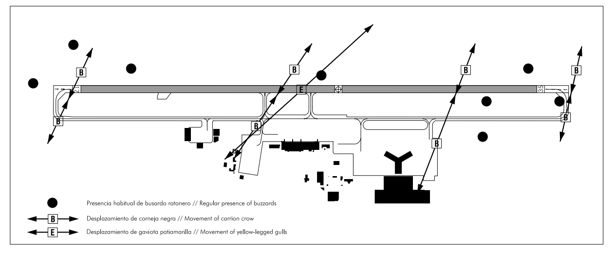
CONCENTRATION AND FLOWS OF BIRDS
Movements of yellow-legged gulls constantly throughout the year, although not with a regular frequency (E). Increased presence in spring and autumnwinter, especially during coastal squalls with predominantly S or SW winds.
Regular presence of common buzzards in the vicinity of both thresholds, flying locally or perching on infrastructure or on the ground. Summer presence of black kites (April-July).
Movements of black crows between the outside and inside of the enclosure (B). Predominant presence and activity of starlings and common swifts in the vicinity of Threshold 35.
Increased presence of European nightjars in May-June and AugustSeptember. Habitually present at threshold 35, apron and taxiways (between D3 and D4).
The movement and habitual presence of birds have been detected in the following areas:
SCREENING BY TREES AT RWY 35 THRESHOLD ANEMOMETER
At the threshold of RWY 35, with winds of direction from 030º to 100º and between 50 m high and the TDZ, there is a discontinuity in the wind intensity which could mean a reduction of up to 70% at the TDZ due to the presence of a nearby forest area, which also influences the readings of the RWY 35 anemometer.
AERONAUTICAL CHARTS RELATED TO AN AERODROME
The list of charts related to the aerodrome can be found on the link below:
VISUAL SEGMENT SURFACE (VSS) PENETRATION
Not applicable.