GCTS AD 2 AERODROME DATA
AERODROME LOCATION INDICATOR AND -NAME
GCTS - TENERIFE SUR
AERODROME GEOGRAPHICAL AND ADMINISTRATIVE DATA
ARP |
280240N 0163421W. See AD 2-GCTS ADC. |
|
Distance and direction from the city |
60 km SW. |
|
Elevation |
64 m / 209 ft. |
|
Geoid undulation |
44.39 m ± 0.10 m (1). |
|
Reference temperature |
28°C. |
|
Low average temperature |
18ºC. |
|
Magnetic variation |
4ºW (2025). |
|
Annual change |
9.8'E. |
|
AD administration |
Aena. |
|
Address |
Aeropuerto de Tenerife Sur - 38610 Granadilla de Abona Tenerife. |
|
TEL |
+34-922 759 000 |
|
FAX |
+34-922 759 247 |
|
AFTN |
GCTS |
|
Approved traffic |
IFR/VFR. |
|
Remarks |
Operations Centre:
(1) For all AD points. |
OPERATIONAL HOURS
Airport |
H24. |
|
Customs and Immigration |
HR AD. |
|
Health and Sanitation |
See GEN 1.4. |
|
AIS/ARO |
H24. (1) |
|
MET briefing |
HR AD. |
|
ATS |
HR AD. |
|
Fuelling |
HR AD. |
|
Handling |
HR AD. |
|
Security |
HR AD. |
|
De-icing |
No. |
|
Remarks |
(1) Centralised AIO Office - International NOTAM Office
Centralised ARO Office Geographical Area 15.
|
HANDLING SERVICES AND FACILITIES
Cargo facilities |
No limitations. |
|
Fuel types |
JET A-1. |
|
Oil types |
None. |
|
Refuelling capacity |
No limitations. |
|
De-Icing facilities |
No. |
|
Hangar space |
No. |
|
Repair facilities |
No. |
|
Remarks |
Ramp agents may attend both commercial and general aviation. Ramp agents: MENZIES GROUND SERVICES
AVIAPARTNER
Handling agents for General and Business Aviation: AviaVIP TFS
GERARDO MELÉNDEZ
BROK-AIR FBO
UNITED AVIATION SERVICES
Fuel: CMD
TERMINALES CANARIOS
Handling agents for aircraft maintenance: TOTAL AVIATION SERVICES
HLA - HISPANO-LUSITANA AVIACIÓN, S.L.
BROK - AIR TECHNICS
BLUE TEAM FLIGHT SCHOOL, S.L
|
PASSENGER FACILITIES
Hotels |
No. |
|
Restaurant |
Yes. |
|
Transportation |
Buses, taxis and hire cars. |
|
Medical facilities |
First aid. 1 ambulance. |
|
Bank/Post Office |
Cash dispensers / No. |
|
Tourist information |
Yes. |
|
Remarks |
None. |
RESCUE AND FIREFIGHTING SERVICES
Fire category |
9 (1). |
|
Rescue equipment |
In accordance with the fire category published. |
|
Removal of disabled aircraft |
Dragging bars, conventional push-back up to B747-400 and A340-600 by handling agents. The airport has lifting and moving gear for ACFT of CAT I/II/III available for the registered owner or operator of the ACFT affected:
|
|
Remarks |
Contact details for disabled ACFT removal:
Prior permission from the executive on duty required only in the case that the means supplied by the airport for movement of disabled ACFT are needed. (1) Level of protection: 9. |
RUNWAY SURFACE CONDITION ASSESSMENT AND REPORTING, AND SNOW PLAN
Types of clearing equipment |
Not applicable. |
|
Clearance priorities |
Not applicable. |
|
Use of material for movement area surface treatment |
Not applicable. |
|
Specially prepared winter runways |
Not applicable. |
|
Remarks |
Runway surface condition assessment and reporting in accordance with the Global Reporting Format (GRF) methodology described in AD 1.2.2. Aerodrome in service during all seasons of the year. |
APRONS, TAXIWAYS AND CHECK LOCATIONS/POSITIONS DATAMOVEMENT AREA DETAILS
Apron |
Surface: Hydraulic concrete. Strength: PCN 85/R/A/W/T, EXC PRKG AG1 to AG5, E64 to E70, S41, H44, R45, H46, R47 and G48: PCN 72/R/B/W/T. PRKG R19 to G25 and E49 to E52: PCN 76/R/A/W/T. |
|
Taxiways |
Width: 23 m. Surface: Asphaltic concrete. Strength:
|
|
Check locations |
Altimeter: Apron ELEV 64 m / 210 ft. VOR: No. INS: See AD 2-GCTS PDC. |
|
Remarks |
TWY centre line: see INSIGNIA and Data Set. |
SURFACE MOVEMENT GUIDANCE AND CONTROL SYSTEM AND MARKINGSTAXIING GUIDANCE SYSTEM AND MARKINGS
Taxiing guidance system |
Runway-holding positions, intermediate holding positions, NO ENTRY and information signs, runway guard lights, no intrusion bars, intermediate holding positions lights and aircraft stands markings. |
|
RWY markings |
Threshold, designators, centre line, touchdown zone, aiming point, side stripe. |
|
TWY markings |
Centre line and side stripe, edge with reflective markers. |
|
Remarks |
None. |
AERODROME OBSTACLES
Obstacles which penetrate Transitional, Conical, Take-off, Inner Horizontal and Approach, surfaces contained in Annex 14 of ICAO; and Area 2A, Area 3 and Area 4 surfaces contained in Annex 15 of ICAO. |
See Item 10 and Data Set. |
|
Remarks |
See AD 2-GCTS AOC. |
METEOROLOGICAL INFORMATION PROVIDEDMETEOROLOGICAL SERVICE PROVIDED
MET office |
Tenerife Sur EMAe. |
|
HR |
H24. |
|
METAR |
Half-hourly. |
|
TAF |
24 HR. |
|
TREND |
Yes. |
|
Briefing |
In person and by telephone. |
|
Flight documentation/Language |
Charts and plain language/Spanish. |
|
Charts |
Forecast significant, wind and temperature at altitude maps. |
|
Supplementary equipment |
Clouds, lightning and radar information image display. |
|
ATS unit served |
TWR, APP. |
|
Additional information |
Las Palmas OMAe (GCGC); H24
Tenerife Sur EMAe: H24
|
|
Remarks |
Aerodrome climatological summary available. Aerodrome warnings available. There is a low level wind shear alert system (LLWAS) that generates wind shear alarms. Aerodrome MET guide available. |
RUNWAY PHYSICAL CHARACTERISTICS
RWY |
Direction |
DIM (m) |
THR PSN |
THR ELEV TDZ ELEV |
SWY (m) |
CWY (m) |
Strip (m) |
OFZ |
RESA (m) |
RWY/SWY SFC PCN |
|---|---|---|---|---|---|---|---|---|---|---|
07 |
068.57° GEO 072° MAG |
3200 x 45 |
280221.14N 0163515.50W |
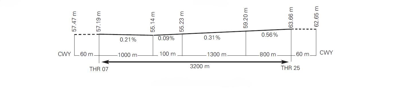
THR: 57.2 m / 188 ft TDZ: 57.2 m / 188 ft |
No |
60 x 150 |
3320 x 300 |
No |
240 x 150 |
RWY: ASPH PCN 94/F/A/W/T (1) SWY: No |
25 |
248.59° GEO 252° MAG |
3200 x 45 |
280259.10N 0163326.43W |
THR: 63.7 m / 209 ft TDZ: 63.7 m / 209 ft |
No |
60 x 150 |
3320 x 300 |
No |
227 x 137 |
RWY: ASPH PCN 94/F/A/W/T (2) SWY: No |
Remarks: (1) First 242 m RWY 07 PCN 142/F/A/W/T. (2) First 190 m RWY 25 PCN 142/F/A/W/T. |
||||||||||
Profile
DECLARED DISTANCES
RWY |
TORA (m) |
TODA (m) |
ASDA (m) |
LDA (m) |
|---|---|---|---|---|
07 |
3200 |
3260 |
3200 |
3200 |
25 |
3200 |
3260 |
3200 |
3200 |
07 INT B2 |
3060 |
3120 |
3060 |
– |
25 INT B6 |
3105 |
3165 |
3105 |
– |
Remarks: None. |
||||
APPROACH AND RUNWAY LIGHTING
Runway |
07 |
|
Approach |
Precision CAT I, 900 m. LIH. |
|
PAPI (MEHT) |
3° (19.67 m / 65 ft). (1) |
|
Threshold |
Green with wing bars. |
|
Touchdown zone |
No. |
|
Runway centre line |
3200 m: 2300 m white + 600 m white and red + 300 m red. LIH. Distance between lights: 15 m. |
|
Runway edge |
3200 m: 2600 m white + 600 m yellow. LIH. Distance between lights: 50 m. |
|
Runway end |
Red. |
|
Stopway |
No. |
|
Remarks |
(1) PAPI not usable by code letter F ACFT, except for the A380. Rapid exit indicator lights (B4, B5). |
Runway |
25 |
|
Approach |
Precision CAT I, 720 m. LIH. |
|
PAPI (MEHT) |
3° (19.44 m / 64 ft). (1) |
|
Threshold |
Green with wing bars. |
|
Touchdown zone |
No. |
|
Runway centre line |
3200 m: 2300 m white + 600 m white and red + 300 m red. LIH. Distance between lights: 15 m. |
|
Runway edge |
3200 m: 2600 m white + 600 m yellow. LIH. Distance between lights: 50 m. |
|
Runway end |
Red. |
|
Stopway |
No. |
|
Remarks |
(1) PAPI not usable by ACFT B747-400 as these do not meet the wheel clearance over THR requirements. Nor by code letter F ACFT, except for the A380. Rapid exit indicator lights (B3). |
OTHER LIGHTING, SECONDARY POWER SUPPLY
ABN/IBN |
No. |
|
WDI |
1 near ARP, 1 near THR 07, 1 near THR 25. LGTD. |
|
TWY lighting |
Centre line. |
|
Apron lighting |
Floodlighting poles and edge at the East side, reflective markers at the West side. |
|
Secondary power supply |
Visual aids system: uninterruptible power supply. Terminal building and apron lighting: emergency engine generators which provide a switch-over time (light) of 15 seconds. |
|
Remarks |
LED lighting on no intrusion bars and intermediate holding positions. |
HELICOPTER LANDING AREA
Situation |
|
|
Elevation |
|
|
Dimensions, surface, maximum weight, markings |
|
|
Lighting |
See items 14 and 15. |
|
Direction |
FATO: see item 12. |
|
Declared distances |
(*) See table. | |
Remarks |
Helicopters operating with a letter of exemption should consult item 20 for further information. |
(*)
RWY |
RTODAH (m) |
TODAH (m) |
LDAH (m) |
|---|---|---|---|
07 INT B6 |
95 |
95 |
95 |
07 INT B2 |
3060 |
3060 |
3060 |
25 INT B6 |
3105 |
3105 |
3105 |
25 INT B2 |
140 |
140 |
140 |
AIR TRAFFIC SERVICES AIRSPACE ATS AIRSPACE
Designation |
CTR TENERIFE SUR. |
|
Lateral limits |
280234N 0164755W; 280431N 0163846W; arc of 8 km centred on GCTS ARP CW to 280519N 0163029W; 281001N 0162336W; arc of 12 NM centred on GCTS ARP CW to 280234N 0164755W. |
|
Vertical limits |
SFC - 1000 ft AGL - 1650 ft AMSL (1). |
|
Airspace class |
D. |
|
Unit Language |
TENERIFE SUR APP. ES/EN. |
|
Transition altitude |
1850 m / 6000 ft. |
|
| Hours of applicability | - | |
Remarks |
(1) Whichever is higher. |
Designation |
ATZ TENERIFE SUR. |
|
Lateral limits |
Circle radius 8 km centred on ARP (2). |
|
Vertical limits |
SFC - 3000 ft HGT (3). |
|
Airspace class |
D. |
|
Unit Language |
TENERIFE SUR TWR. ES/EN. |
|
Transition altitude |
- |
|
| Hours of applicability | - | |
Remarks |
(2) Or the ground visibility, whichever is lower. (3) Or up to the clouds ceiling, whichever is lower. |
AIR TRAFFIC SERVICES COMMUNICATION FACILITIESATS COMMUNICATION FACILITIES
Service |
Call sign |
FREQ |
HR |
Remarks |
|---|---|---|---|---|
APP |
Tenerife Sur APP |
127.700 MHz |
H24 |
APP/L Primary |
128.125 MHz |
H24 |
APP Secondary |
||
TWR |
Tenerife Sur TWR |
119.000 MHz |
H24 |
- |
120.300 MHz |
H24 |
BACKUP |
||
121.750 MHz |
H24 |
CLR |
||
121.900 MHz |
H24 |
GMC |
||
121.500 MHz |
H24 |
EMERG |
||
243.000 MHz |
H24 |
EMERG |
||
ATIS |
Tenerife Sur Information |
118.675 MHz |
H24 |
- |
D-ATIS |
Tenerife Sur Information |
NIL |
H24 |
Provision of ATIS information via data link. |
RADIO NAVIGATION AND LANDING AIDSRADIO NAVIGATION & LANDING FACILITIES
Facility (VAR) |
ID |
FREQ |
HR |
Coordinates |
DME ELEV |
Remarks |
|---|---|---|---|---|---|---|
DVOR (4º W) |
TFS |
116.400 MHz |
H24 |
280008.8N 0164116.5W |
- |
COV 10NM signal fluctuations BTN R-030/R-360 CCW BLW 15000 ft AMSL; COV 40 NM BTN:
|
DME |
TFS |
CH 111X |
H24 |
280008.8N 0164115.0W |
30 m |
COV 40 NM BTN:
|
LOC 07 (4º W) ILS CAT I |
ITS |
109.700 MHz |
H24 |
280302.9N 0163315.5W |
- |
072° MAG / 319 m FM THR 25. COV 17 NM AVBL BTN ±35º FM RCL at 4000 ft AMSL or ABV. COV 25 NM AVBL BTN ±10º FM RCL at 2500 ft AMSL or ABV. |
GP 07 |
- |
333.200 MHz |
H24 |
280221.6N 0163501.1W |
- |
3°; RDH 15.3 m; at 372 m FM THR 07 & 130 m FM RCL to the right on APCH direction. Full FLY-UP indications may not be received BLW GP beyond 5º Right FM RCL. |
ILS/DME 07 |
ITS |
CH 34X |
H24 |
280221.6N 0163501.1W |
60 m |
REF DME THR 07. |
LOC 25 (4º W) ILS CAT I |
ISUR |
110.900 MHz |
H24 |
280217.5N 0163525.8W |
- |
252° MAG / 303 m FM THR 07. AVBL BTN ±35º of RCL FM 17 NM (15.4 NM DME) & ABV 4000 ft AMSL & ±10º of RCL FM 25 NM (23.4 NM DME) & ABV of 2300 ft AMSL. |
GP 25 |
- |
330.800 MHz |
H24 |
280251.7N 0163337.0W |
- |
3°; RDH 15.5 m; at 352 m FM THR 25 & 107 m FM RCL to the left on APCH direction. It may not be received full FLY-UP indications BLW GP FM 6º left of RCL. |
ILS/DME 25 |
ISUR |
CH 46X |
H24 |
280251.7N 0163337.0W |
66 m |
REF DME THR 25. |
LOCAL AERODROME REGULATIONSLOCAL REGULATIONS
GENERAL AND BUSINESS AVIATION
It is mandatory to have a handling agent for all General and Business Aviation operations.
It is forbidden to cross the taxiways in the apron on foot.
ATC PROCEDURES
Even if the runway is temporarily occupied by other traffic, landing clearance may be issued to an arriving ACFT if the controller is satisfied that at the time the ACFT crosses the threshold of the runway in use, the prescribed separation from the preceding ACFT shall exist.
When issuing a "Landing Clearance based on Anticipated Separation", ATC shall use the following phrasing: "...(Call sign) BEHIND LANDING/DEPARTING (ACFT type) CLEARED TO LAND RUNWAY (number)".
This procedure may be used between sunrise and sunset and without detriment to the requirements established in the Reglamento de la Circulación Aérea (paragraph 4.10.2.4, Fourth Book, Chapter 10) referring to the use of conditional phrases for movements affecting the runway or runways in activity.
STANDARD TAXIING PROCEDURES
START-UP
- Pilots shall request clearance to start up from CLR on the appropriate frequency or DCL. On requesting this clearance, the ACFT must be completely ready to start up, considering that the ACFT must leave the stand 10 minutes before the CTOT.
- Clearance shall be issued as soon as requested. When delays are expected to exceed 15 minutes, ATC shall provide the appropriate start up time. At that moment, ATC clearance shall be issued.
REQUEST FOR ATC CLEARANCE AND START-UP VIA DATA LINK
Pilots may request ATC clearance and permission to start up on the corresponding frequency or data link (DCL).
For more information about the DCL service, see AIP ENR 1.5, section 3. DEPARTING FLIGHTS: ATC and start-up clearance via data link (DCL).
In cases of discrepancies, voice commands will always prevail over data link.
The pilot may request ATC clearance via DCL no earlier than 30 minutes before the EOBT.
-
The pilot shall request ATC and start-up clearance simultaneously via RCD. The RCD message should contain the following data:
-
Aircraft call sign according to the submitted flight plan (FPL).
-
Aerodrome of origin.
-
Stand occupied.
-
Destination aerodrome.
-
Letter corresponding to the ATIS information received.
-
ICAO aircraft type designator.
Any free text sent via the RCD by the pilot will not be considered by ATC. Special requests must always be made via voice command.
-
-
The pilot will receive a message of acceptance, "RCD RECEIVED", or cancellation, "RCD REJECTED".
-
In the case of acceptance, ATC will issue a CLD message with the following fields:
-
Aircraft call sign.
-
Destination aerodrome.
-
Runway assigned for departure.
-
Departure procedure (SID). Note: The initial altitude will be that of the published SID.
-
SSR code mode A (SQUAWK).
-
CTOT, if one is held.
-
Next frequency.
-
Letter of the current ATIS information.
-
Additional information, which shall include clearance to start up or instructions for requesting this, in the case of failure to comply with the start-up approval parameters in accordance with the EOBT.
-
-
When an RCD message is sent in the valid range of EOBT, ATC and start-up clearance will be received. If the pilot is not ready for start-up, he/she shall not accept the clearance and shall contact the controller by voice when ready.
-
When an FSM message of the type "REVERT TO VOICE PROCEDURES" is received, data link communication will be terminated and the revert to voice procedure shall apply.
-
When a CLD message is received:
-
If any inconsistency is detected in the received message, the pilot shall revert to voice procedures and request a new clearance.
-
If the pilot considers the CLD clearance message to be correct, he/she must respond via data link with a CDA message (Departure Clearance Echoback).
-
-
If the ATC system does not receive a CDA message from the pilot within the waiting time, or a CDA inconsistent with the previous CLD message is received, communication via data link will be terminated and a "CDA REJECTED" message will be received in the FMS.
-
When a correct CDA message is received, the ATC system will send the aircraft a "CLEARANCE CONFIRMED" message in the FMS and will terminate the communication via data link.
INTERCHANGE OF DATA WITH NMOC – ADVANCED ATC TWR
In Tenerife Sur the procedures established for airports with Advanced ATC Tower are applied. Therefore, by means of A-DPI message, the target take-off time (TTOT) calculated from actual off-block time (AOBT) of all departure instrumental flights is provided to the Network Manager Operations Center (NMOC).
From the moment of the A-DPI reception, neither DLA nor CHG messages modifying flight plan data will be accepted. If it is regulated, the assigned CTOT prior to the A-DPI reception is maintained.
If an aircraft has to abort taxiing due to technical reasons, the airport will send a C-DPI message to NMOC. As a result of that C-DPI, the flight plan will be suspended and the operator will be informed by a FLS message with the remark "Suspended by departure airport". The flight plan can be activated again by means of an updated EOBT with a DLA message.
GROUND MOVEMENT
Departures
Pilots shall communicate with TWR to request towing, powerback and/or taxiing permission.
After push-back or autonomous departure, aircraft shall proceed to the threshold in use through the first available apron gate, unless there are operational or safety reasons to the contrary (compliance with CTOT, improvements to the take-off sequence, request for opposite runway, inner apron taxiway occupied due to push-backs or aircraft, etc.).
- Push-back and taxiing manoeuvre
A. Pushback is obligatory in front stands and shall be performed such that the aircraft remains nosing to the threshold in use and leaving apron gates "D" free, except when:
-
There are operational or safety reasons for push-backs without nosing to the threshold in use or leaving apron gates D free.
-
There are limitations on engine starts, which must be communicated to ATC in advance.
-
Pushbacks on parking stands R19, G20, AG21, and J22 shall be performed nosing to THR 25.
A1. Simultaneous pushback on adjacent stands is not permitted, nor is pushback from a stand with a simultaneous entry to the adjacent stand, unless the following criteria are met:
- Both aircraft are informed of the manoeuvre.
- In the event of simultaneous pushbacks towards the same direction, one aircraft initiates the pushback first and performs a long pushback and the other performs a short pushback; or one aircraft performs a pushback nosing to the threshold in use and the other performs a pushback nosing to the opposite threshold, provided that an apron gate is available between the two aircraft.
-
Simultaneous arrival/departure manoeuvres from adjacent stands J1 and G2, G9 and G10 and G10 and H37 are incompatible.
A2. Avoiding collisions with other ACFT and obstacles is the responsibility of:
-
Pilots, when taxiing on the apron.
-
Ground handling companies during parking stand push-back exit manoeuvres.
B. Autonomous exits shall be made using the lowest possible starting power and in such a way that the idle power is not exceeded when turning. Departure shall be performed nosing to the threshold in use may be modified if there are operational or safety reasons to the contrary.
- Powered pushback manoeuvre (powerback)
The performance of powered pushback manoeuvres (powerback) requires prior clearance from Airport Management and shall be performed under the full responsibility of the aircraft operator. The company representative must request this operation, in good time, from Airport Management for the safety analysis of the operation.
- Push and hold manoeuvre
When an aircraft in a position requiring towed pushback is affected by regulations and fully ready to operate (start-up), the pilot may request a "Push and Hold" from ATC. Provided that there is availability, CEOPS shall assign a remote parking stand with autonomous exit from E64 to E70.
This manoeuvre is limited to aircraft whose dimensions are equal to or less than those of the MAX ACFT of the cleared parking stands.
Arrivals
The ACFT shall notify the ATC runway vacated.
All fixed-wing aircraft shall always access the apron or parking stand with "FOLLOW ME" vehicle guidance, from the appropriate apron gate for PRKG R19 to G48, and from the parking stand centre line for PRKG E49 to E70.
Simultaneous entries of aircraft into adjacent stands is not permitted, nor is entry into a stand with simultaneous pushback from an adjacent stand, unless both aircraft are informed of the manoeuvre.
Simultaneous entries/exit manoeuvres from adjacent stands J1 and G2; G9 and G10; and G10 and H37 are incompatible.
TAXIING RESTRICTIONS
Runway entry/exit:
TWY |
MAXIMUM AIRCRAFT ALLOWED AND OTHER RESTRICTIONS |
|---|---|
B1 |
D |
B2 |
Runway entry: D and maximum length 50 m and maximum span 51 m (runway exit without restrictions). |
B3 (RWY 25 rapid exit) |
Exit turn to the East: D (others without restrictions). |
B5 (RWY 07 rapid exit) |
Not usable by A-340-600 and B-777-300. |
B6 |
D except B-767-400. Runway entry maximum length 58 m. |
Apron entry/exit:
With the exception of traffic guided by signal man, the following restrictions shall be apply:
TWY |
MAXIMUM AIRCRAFT ALLOWED AND OTHER RESTRICTIONS |
|---|---|
D1 |
Entry from RWY 25 which have vacated the runway via TWY B1 or B2: D except B-767. Exit to RWY 07: D except B-767. |
Taxiways for general aviation (TWY U1, U2 and U3) are limited to aircraft with maximum wingspan of 22 m.
AIRCRAFT WASHING
Several stands have been enabled for this purpose, for companies who wish to perform washing of fuselages on the apron, shall request clearance from:
- Centro de Operaciones (CEOPS)
- TEL: +34-922 759 233
- E-mail: tfsopya@aena.es
RESTRICTIONS ON STANDS
On PRKG J-1, G-2, J-3, G-4, J-5, R-5A, G-6, J7, J8, G9 and G10:
-
It is mandatory to use the 400 Hz facilities.
-
The use of the air conditioning facilities shall be mandatory when the ACFT air conditioning is needed.
-
The use of the aircraft APU is forbidden at these stands in the period between 2 minutes after blocks upon arrival and 5 minutes before off-block at departure.
The aircraft APU can only be used when the 400 Hz facilities and the mobile units are not operative, or when the air conditioning service is needed and the air conditioning equipment is not available.
ACFT with inoperative APU must communicate this incident to CEOPS. If the APU must be switched on for technical reasons, the ground handling agent must request clearance from the Airport Operations Coordination Centre (CEOPS).
ENGINE TEST PROCEDURE
Engine tests may be performed on the apron and on the A2 holding bay, depending on the category of the aircraft and engine speed requested.
Idle power engine tests may be authorised on the apron only on the second line PRKG: E49, E50, E51, E52, E53, E54, E55, E56, E57, E58, E59, E60, E61, E62, E63, E64, E65, E66, E67, E68, E69, E70 and general aviation apron: PRKG AG1, AG2, AG3, AG4 and AG5.
First line idle and average power engine tests are not authorised.
Full power engine tests may only be performed on the A2 holding bay.
Engine tests at higher than idle speed are prohibited between 0000 and 0600 LT. In this range, the only tests admitted in higher than idle speed are those that are essential for ACFT flight departure and scheduled time of take-off between 0400 and 0600 LT.
Clearance must be requested from the operations centre (CEOPS) in order to perform engine tests.
- TEL: +34-922 759 233
- E-mail: tfsopya@aena.es
OPERATION OF HELICOPTERS
GENERAL
In general, as no specific zone to operate with helicopters is defined other than RWY 07/25, all flights will be treated as for fixed-wing ACFT and shall be cleared by ATC to take off and land on that runway. Thus, a FATO is defined on RWY 07/25 which covers the zone lying between the two thresholds. Helicopters on operational missions, or those so requiring for reasons of safety or performance, may operate according to local procedures following ATC instructions.
The operational schedule for helicopter operations is H24 (special operational ones whose letter of exemption so permits, and IFR). In cases of visual flights, the schedule shall be sunrise to sunset.
STANDS
The stands for helicopters are located in the East and West zones of the apron (see AD 2-GCTS PDC).
The characteristics of the helicopters that can operate, as determined by the possible stands assignable, are:
PRKG |
Model |
|
|---|---|---|
| East apron | E49 |
AW-101 |
R19 |
AW-101 |
|
J22 |
AW-101 |
|
| General Aviation apron | AG2 |
SA-316 |
AG5 |
SA-316 |
OPERATIONAL RESTRICTIONS
Either air or ground taxiing is permitted, depending on the type of helicopter, and this shall be accomplished using the taxiways also assigned to the use of fixed-wing ACFT. The pilot-in-command shall take into account the widths of the taxiing routes defined and the dimensions of the assigned stand and their safety area.
Neither air nor ground taxiing of entry or exit to the stand are permitted while an ACFT is boarding or disembarking passengers at adjacent stand.
DESCRIPTION OF THE OPERATION
LANDING ON RUNWAY AND PARKING ON CIVIL APRON
Direction 07: helicopters shall proceed, following ATC instructions, to final approach to RWY 07.
-
Assigned PRKG AG2 or AG5. Helicopters shall vacate the runway, preferably, via B2, and shall be cleared by ATC to taxi via TWY T in direction East up to gate D1, where a "FOLLOW ME" vehicle will be waiting to guide them up to the stand.
-
Assigned PRKG R19 or J22. Helicopters shall vacate the runway, preferably, via B4, and shall be cleared by ATC to taxi via TWY T in direction West up to gate D6, where a "FOLLOW ME" vehicle will be waiting to guide them up to the stand.
-
Assigned PRKG E49. Helicopters shall vacate the runway, preferably, via B4, and shall be cleared by ATC to taxi via TWY T in direction West up to the centre line of the stand itself, where a "FOLLOW ME" vehicle will be waiting to guide them in the parking manoeuvre.
Direction 25: helicopters shall proceed, following ATC instructions, to final approach to RWY 25.
-
Assigned PRKG AG2 or AG5. Helicopters shall vacate the runway, preferably, via B3, and shall be cleared by ATC to taxi via TWY T in direction West up to gate D2, where a "FOLLOW ME" vehicle will be waiting to guide them up to the stand.
-
Assigned PRKG R19 or J22. Helicopters shall vacate the runway, preferably, via B4, and shall be cleared by ATC to taxi via TWY T in direction West up to gate D6, where a "FOLLOW ME" vehicle will be waiting to guide them up to the stand.
-
Assigned PRKG E49. Helicopters shall vacate the runway, preferably, via B4, and shall be cleared by ATC to taxi via TWY T in direction West up to the centre line of the stand itself, where a "FOLLOW ME" vehicle will be waiting to guide them in the parking manoeuvre.
PARKING ON CIVIL APRON AND TAKE-OFF FROM RUNWAY
Direction 07:
-
Assigned PRKG AG2 or AG5. Subject to ATC clearance, preferably, helicopters shall taxi along the apron centre line up to gate D1, then TWY T to access runway via B2 for take-off.
-
Assigned PRKG R19, J22 or E49. Subject to ATC clearance, preferably, helicopters shall taxi up to gate D6, TWY T to access runway via B6 for take-off.
Direction 25:
-
Assigned PRKG AG2 or AG5. Subject to ATC clearance, preferably, helicopters shall taxi along the apron centre line up to gate D1, TWY T to access runway via B2 for take-off.
-
Assigned PRKG R19, J22 or E49. Subject to ATC clearance, preferably, helicopters shall taxi up to gate D6, TWY T to access runway via B6 for take-off.
OPERATION OF CODE LETTER F AIRCRAFT
The procedure described below is valid for occasional operations of the following code letter F aircraft: B748, A124, A225 and A388.
The arrival or stop over of code letter F aircraft is not authorised if it has not received prior authorisation by the Airport Management.
B748 and A124
The assigned stands are S41 and R19.
Taxiing by code letter F aircraft (B748 and A124) shall always be with the accompaniment of a "FOLLOW ME" vehicle, which will attend them throughout taxiing from the stand up to TWY T, as well as from the apron holding positions (D6 and D1) to the stand, upon arrival.
RUNWAY IN USE |
ARR / DEP |
TAXI ROUTE |
PRKG |
|---|---|---|---|
07 |
ARR |
Vacate via TWY B7, then TWY T up to intermediate holding position before D6, guided taxiing to PRKG via D2 |
S41
|
DEP |
Guided exit via D2 up to TWY T, TWY B0 |
||
ARR |
Vacate via TWY B7, then TWY T up to intermediate holding position before D6, guided taxiing to PRKG via D6 |
R19 |
|
DEP |
Guided exit via D6 up to TWY T, TWY B0 |
||
25 |
ARR |
Vacate via TWY B2, then TWY T up to holding position D1, guided taxiing to PRKG via D2 |
S41
|
DEP |
Exit via D2 up to TWY T, TWY B7 |
||
ARR |
Vacate via TWY B2, then TWY T up to holding position D1, guided taxiing to D6 to PRKG |
R19
|
|
DEP |
Exit via D6 up to TWY T, TWY B7 |
AN225 and A388
The assigned stand is S41.
Taxiing by code letter F aircraft (A225 and A388) shall always be with the accompaniment of a "FOLLOW ME" vehicle, which will attend them throughout taxiing from the stand up to the runway-holding positions upon departure, while for arrivals, once they have left the runway, guidance shall be from the apron holding positions to the stand.
In the case of arrival of an A388 via threshold THR 25, the aircraft will be guided by a "FOLLOW ME" vehicle from runway exit to the stand.
RUNWAY IN USE |
ARR / DEP |
TAXI ROUTE |
PRKG |
|---|---|---|---|
07
|
ARR |
Vacate via TWY B7, guided taxiing from TWY B6 to RWY 07, TWY B3 and via D2 up to PRKG |
S41
|
DEP |
Exit via D2 up to TWY T, TWY B0 |
||
25
|
ARR |
Vacate via TWY B2 up to D1, guided taxiing to PRKG. Except for A388: Guided taxiing up to PRKG from TWY B2 |
|
DEP |
Exit via D2, guided taxiing via TWY T up to D1, access RWY via TWY B2, exit it via TWY B5, and taxi up to TWY B7 |
Operational and Taxiing Restrictions:
-
The PAPI indications cannot be used by code letter F aircraft, except for the A388.
-
Oversteering manoeuvres are required to correct the path on curved sections of the taxiways.
B748 and A124: TWY B2, B7, D2 and D6.
A388 and A225: TWY B2, B3, B5, B6, B7 and D2.
-
Prior to the operation (arrival/departure) of a code letter F aircraft, a "FOLLOW ME" vehicle will inspect the route to be taken by the aircraft, including the runway, as determined by the runway in use and the stand assigned.
-
After take-off, a "FOLLOW ME" vehicle shall inspect the route taken, including the runway.
-
Code letter F aircraft shall taxi at reduced speed, with the engines idling (whenever possible) and with the outer engines off so as to avoid the intake and generation of FOD.
OPERATIONAL SAFETY REPORTS
Pilots/operator shall report to the airport as soon as possible about any accidents, incidents, occurrences or events which may have a potential operational impact and in which they have been involved or witnessed.
The aim of these reports is the compilation of the information in order to improve operational safety, independently of the compulsory report of the occurrence to the appropriate aeronautical authority. Data may be sent in any format, including at least the following information:
-
Date and time.
-
Site.
-
Parties involved (data used to identify vehicles, ACFT…involved).
-
Companies implicated.
-
Description of the facts.
-
Any other data considered relevant (e.g. lighting conditions, weather, phase of the operation such as take-off / landing / stopover, pavement conditions…).
Contact e-mail address of the airport, for the reception of operational safety reports, is the following: tfs.seguridadoperacional@aena.es
In addition to notifying the airport by means of the indicated system, it is necessary to send at least basic data of the accident, incident, occurrence or event to the air traffic control service provider (ATC).
On the specific instance of safety reports related with the air traffic control service provider (manoeuvring area, flight phases and ATS airspace) these may be sent to the e-mail address: canariassafetymanagement@enaire.es
MINIMUM RUNWAY OCCUPANCY TIME
ARRIVALS
To minimise the runway occupancy time and the possibility of "go-around", pilots are reminded:
-
Whenever the conditions of the runway so allow, they should use the following exit taxiways/RET, unless otherwise instructed by ATC. Otherwise, they must notify ATC in the first communication with TWR.
AIRCRAFT CATEGORY DUE TO WAKE TURBULENCE |
RWY 07 DIST THR-RET/EXIT |
RWY 25 DIST THR-RET/EXIT |
|---|---|---|
FOUR-ENGINED WITH WIDE-BODY |
B4 1800 m |
B3 2000 m |
HEAVY |
B4 1800 m |
B3 2000 m |
MEDIUM (JETS) |
B4 1800 m |
B3 2000 m |
-
To vacate the runway rapidly and at the highest possible speed without prejudice to safety.
-
To adjust the taxiing speed on the runway after touchdown if they are sure they will not be able to use the planned exit taxiway/RET, avoiding low speeds on the runway.
-
To vacate the runway completely before stopping. Should they not be able to contact GMC, after leaving the runway free, they should hold position until they establish that communication.
DEPARTURES
-
Pilots shall be ready for departure when they reach the runway holding position.
-
When they receive clearance to line up, pilots must be ready to taxi and line up on the runway as soon as the preceding aircraft has started its take-off run or landing roll.
-
Pilots who require additional separation (because of wake turbulence or some other reason), shall notify ATC as soon as possible, and always before entering the runway.
-
Pilots shall start the take-off run immediately after receiving clearance for take-off.
-
Pilots who cannot comply with this requirement shall inform ATC as soon as possible and await instructions. If necessary, ATC may cancel the clearance and instruct the aircraft to vacate the runway.
NOISE ABATEMENT PROCEDURES
GENERAL
-
The following procedures have been established to avoid excessive noise in the surroundings of Tenerife Sur airport.
-
These procedures are applicable to all landings and departures during the indicated time period. Non-compliance with these procedures shall give rise to sanctions upon to the aircraft operator.
-
Pilots and ATC may omit these procedures only for safety reasons.
-
The term night is applicable to the time period comprised between 2300-0700 LT.
-
VFR or IFR test or training flights are forbidden at night time for aircraft with code letter C or higher.
-
Operators which cannot comply with these procedures shall submit the procedure that they can apply for this purpose to the corresponding authority for its possible approval.
-
The restrictions for landing and take-off are only applicable to jets.
GROUND ENGINE TEST
See AD 2-GCTS item 20. "ENGINE TEST PROCEDURE".
NOISE ABATEMENT PROCEDURES
- TAKE-OFF
-
Take-off power. Take-off FLAP/SLAT. Accelerate up to V2 + 10 kt. Climb up to 1500 ft AGL maintaining V2 + 10 kt.
-
At 1500 ft
Reduce to climbing power.
Accelerate up to VZF + 10 kt maintaining a minimum climb gradient of 500 ft/min. (VZF: Minimum flap safety manoeuvre speed).
Retract FLAP/SLAT, according to need.
-
UP TO 6000 ft
Do not exceed 250 kt and continue SID in force, except with ATC clearance.
-
Aircraft taking off from RWY 07 shall maintain R-073 TFS up to 10.0 DME TFS before any right turn is initiated.
-
Aircraft taking off from RWY 25 and overflying DVOR/DME TFS shall not turn right before going past this radioaid.
-
- LANDING
-
At night time, visual approaches shall avoid overflying inhabited areas.
-
At night time, visual approaches to RWY 25 coming from the West (GANTA-DVOR/DME TFS), shall not initiate the left turn before 10.0 DME TFS.
-
Landing and approach procedures under visual meteorological conditions shall be performed with an angle equal to or greater than the ILS GP or PAPI of each runway.
USE OF ENGLISH LANGUAGE IN RADIO COMMUNICATIONS
Whenever there is a pilot on the frequency/frequencies in use in the manoeuvring area who does not speak Spanish, the use of English in ground-air communications between aircraft and the ATS unit shall be mandatory; without prejudice to the application of the provisions in SERA.2010 under 'Responsibilities of the pilot in command', and the decisions which may be taken by the pilot in command in such circumstances, and likewise in the emergency situations which could arise on board the aircraft, and in the adoption by the air traffic controller of the measures it may deem necessary to maintain safety.
This is applicable, as appropriate, in the operational scenarios described in Annex IV to the Real Decreto 1180/2018:
-
The following operations of landing and take-off:
-
Clearances to land with traffic in the holding position.
-
Clearances to take off with traffic on final approach.
-
Clearances to enter and line up from congested holding positions.
-
-
Operations in which there are aircraft entering the active runway, but which are neither going to land or to take off. Typically, these operations are taxiing along the active runway or crossing the active runway.
In the foregoing operational scenarios, Spanish may be used in ground-air communications between the aerodrome traffic control units and flights operating under visual flight rules (VFR), always provided that the pilots do not possess appropriate English language proficiency.
Special operations, in the foregoing operational scenarios, are exempt from applying what is indicated in this section in relation to ground-air communication between aircraft and ATS unit.
FLIGHT PROCEDURES
ATS SURVEILLANCE SYSTEMS
ATS surveillance systems are used in the provision of the aerodrome control service, to perform the following functions:
-
Flight path monitoring of aircraft on final approach;
-
Flight path monitoring of other aircraft in the vicinity of the aerodrome;
-
Establishing the separation specified in article 4.6.7.3 of the R.C.A. between consecutive departing aircraft;
-
Providing navigation assistance to VFR flights.
However, the provision of functions b) and d) in the southern half of the ATZ below 500 ft AMSL and in the northern half of the ATZ, below 2400 ft AMSL, is not guaranteed whenever the Pozo de las Nieves RADAR is available.
In the case that only the Tenerife Sur RADAR is available, the provision of functions b) and d) in the southern half of the ATZ below 800 ft AMSL and in the northern half of the ATZ, below 2800 ft AMSL, is not guaranteed.
All the functions (a), b), c) and d)) will be suspended in the event of a simultaneous unavailability of the Tenerife Sur and Pozo de las Nieves RADAR.
LOW VISIBILITY PROCEDURES (LVP)
Low Visibility Procedures (LVP) are not available at Tenerife Sur airport.
MOVEMENT AREA OPERATIONAL STANDSTILL PROCEDURE (PPOAM)
Tenerife Sur Airport has a Movement Area Operational Standstill Procedure (PPOAM) when RVR is lower than 550 m to maintain safety in the movement area in circumstances of low visibility, which consists of the following phases:
PHASE I: NOTICE
This will be initiated when:
-
800 m > RVR ≥ 550 m,
-
1000 m > VIS ≥ 800 m, if the RVR value is not available.
Notification to all concerned services and users to prepare.
PHASE II: OPERATIONAL STANDSTILL
This will be initiated when:
-
RVR < 550 m or
-
VIS < 800 m, if the RVR value is not available.
TWR shall not authorize operations while these conditions persist, except special operations provided for in the procedure.
PHASE III: RESUMPTION OF OPERATIONS
This will be initiated when:
-
RVR ≥ 550 m or
-
VIS ≥ 800 m, if the RVR value is not available.
Information for pilots:
Defined meteorological minima for procedure.
PHASES |
RVR (m) |
VIS (*) |
|---|---|---|
Phase I - NOTICE |
800 m > RVR ≥ 550 m |
1000 m > VIS ≥ 800 m |
Phase II - OPERATIONAL STANDSTILL |
RVR < 550 m |
VIS < 800 m |
Phase III - RESUMPTION OF OPERATIONS |
RVR ≥ 550 m and trend towards improvement |
VIS ≥ 800 m and trend towards improvement |
(*) VIS values only applicable when the RVR value is not available. |
||
INFORMATION FOR PILOTS
Uncertainty about position in the manoeuvring area: In the face of doubt about the position of the ACFT in relation to the manoeuvring area:
-
If you recognise that you are not on a runway, halt the ACFT immediately and notify this circumstance to ATC (including the last known position).
-
If you recognise that you are on a runway, immediately notify this circumstance to ATC (including the last known position), and vacate the runway as soon as possible, if you can find an appropriate TWY nearby, unless ATC should indicate otherwise, and then, halt the ACFT.
BREAKDOWN OF AN AIRCRAFT: Notify the situation to ATC and await the arrival of assistance. In the event of being on a runway, if possible and unless ATC should indicate otherwise, vacate it.
LOSS OF VISUAL CONTACT BETWEEN MOVING ELEMENTS: In the event of loss of visual contact by an ACFT with another or with a vehicle with which it is maintaining its own separation, ATC shall be informed immediately and the ACFT halted.
COMMUNICATIONS FAILURE:
-
Departing ACFT: the ACFT shall continue by the assigned route and halt at the limit of ATC clearance, taking extreme care, where it shall maintain its position and await the arrival of an assistance vehicle.
-
Arriving ACFT: if the ACFT has just touched down, it will maintain its position on vacating the runway and await the arrival of an assistance vehicle. If the ACFT already holds ATC taxiing clearance, it shall continue by the assigned route and halt at the limit of that clearance, taking extreme care, where it shall maintain its position and await the arrival of an assistance vehicle.
CONTINUOUS DESCENT OPERATIONS
Depending on traffic situation, and if no need for interrupting the descent is foreseen, aircraft will be cleared to proceed to a standard arrival (STAR), or by means of a "direct to" clearance to an intermediate fix of the STAR, to the IAF, to an intermediate approach fix or to the IF, to the minimum altitude of the IAF or the IF of the instrumental procedure (IAC), in order to allow a continuous descent operation.
ADDITIONAL INFORMATION ABOUT RNP Z RWY 07 (LPV ONLY) AND RNP Z RWY 25 (LPV ONLY) MANOEUVRES
According to the most recent version of the EGNOS SoL SDD, Tenerife sur Airport is located within an area lie with a continuity risk that is acceptable, but higher than that committed for APV-I service in the greater part of the territory (mainland and islands) of the member states of the European Civil Aviation Conference (ECAC).
Taking into account the stated above circumstance, aircraft with capacity to use the EGNOS system might suffer losses of continuity more frequently than normal on the final section of RNP Z RWY 07 (LPV ONLY) and RNP Z RWY 25 (LPV ONLY) approach procedure. Nevertheless, in the event of unavailability of the EGNOS system, RNP approaches with other types of minima (LNAV/VNAV, LNAV, present in the RNP Y RWY 07 and RNP Y RWY 25) y and conventional approaches would be available.
Crews are reminded of the importance of checking during pre-flight whether the EGNOS signal availability predictions are appropriate for the operation envisaged at the destination. Consult the AIC "Implementation of RNP APCH manoeuvres published under the title RNP" for more details.
For further information about predictions of EGNOS availability, consult the AIC "Means of notification of the availability/operational status of satellite navigation systems (GNSS) and instrument procedures with authorized use of GNSS"
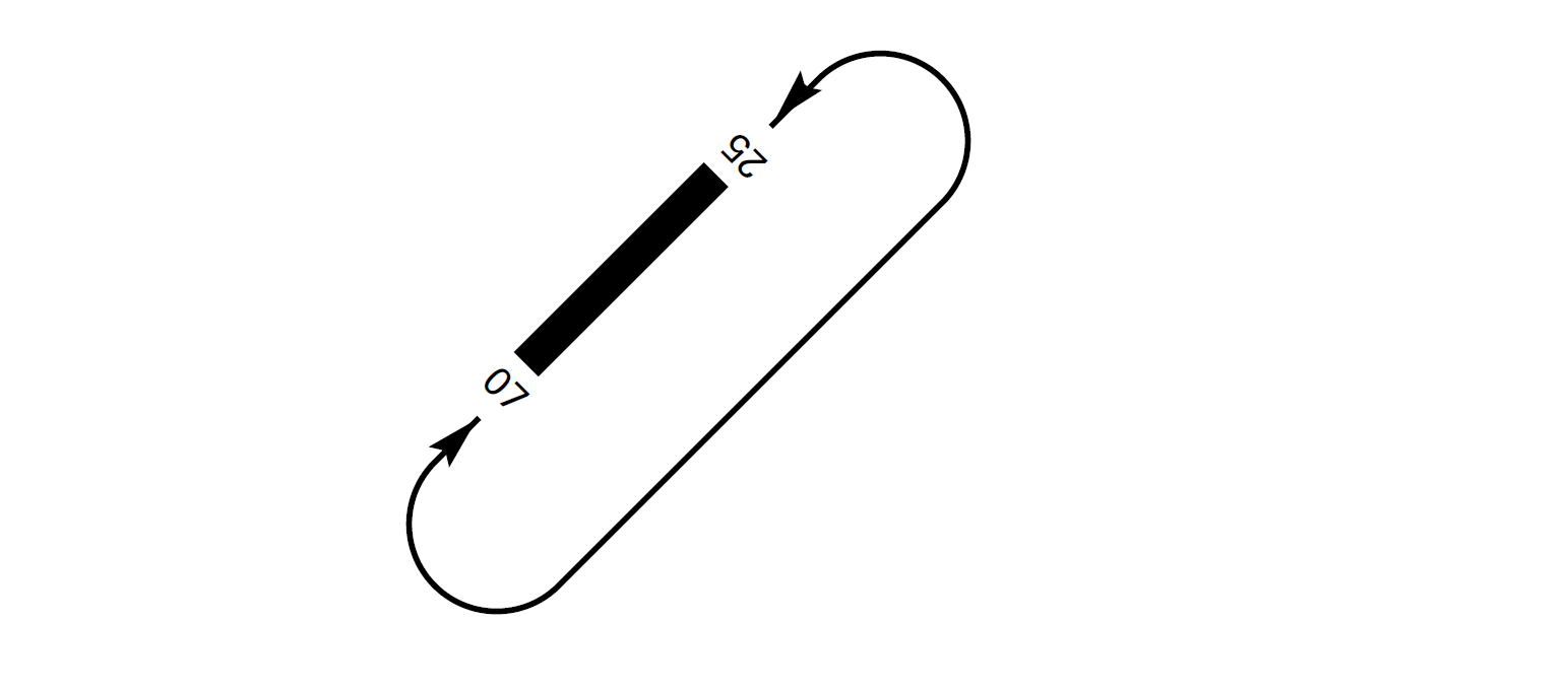
AD TRAFFIC CIRCUIT
ADDITIONAL INFORMATION
Caution: glare may be produced by hand-held lasers. Crew should report any such event and its possible location to ATC services.
WILDLIFE CONTROL SERVICE
Hours: from sunrise to sunset.
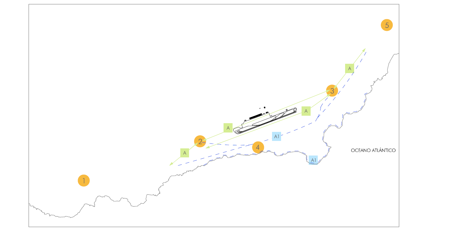
BIRD CONCENTRATION AREAS
The following yellow-legged gull concentration and passage areas can be identified near the airport compound:
-
Area 1: mountain Guaza (at 6.3 NM).
-
Area 2: golf course (at 1.1 NM from THR 07).
-
Area 3: irrigation ponds (at 0.9 NM from THR 25).
-
Area 4: greenhouses located to the south of the airport (at 0.31 NM from the runway).
-
Area 5: Environmental Complex of Tenerife (at 5.4 NM).
MOVEMENTS OF BIRDS

Movement A: movement of yellow-legged gull. This specie is permanently in the area.

Movement A1: movement of yellow-legged gull, more frequent between February and July.
WIND PHENOMENA
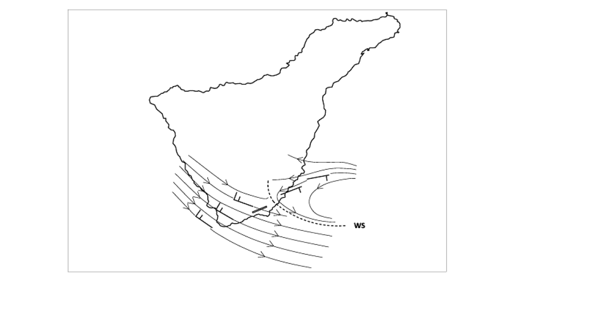
Orographical conditions on the island of Tenerife and the airport situation favour the appearance, in certain circumstances, of wind shear and turbulence phenomena.
OROGRAPHICAL WIND SHEAR IN TRADE WIND REGIME, MAINLY AFFECTING RWY 07
Under trade wind conditions (NE-E), due to the topography of the island, the occurrence of orographical wind shear is frequent. Wind shear is appreciable on final approach (below 1600 ft) to the RWY 07 or on runway, being positive and more frequent in the summer. The surface wind intensities must be around 15 kt and NE-E direction for the effect to appear (positive wind shear 15 to 35 kt).
On approach to RWY 07 below 2100 ft, the wind is usually variable or with intensities of the order of 5-10 kt and SW-NW direction (tailwind), becoming NE-E direction (headwind) and with intensities of at least 10 kt when wind shear is encountered, around 1000-500 ft AGL.
This wind shear effect is most obvious in trade wind (NE-E) situations with incoming air from the Sahara, when there may also occur turbulence on final approach. Values of temperature above 30°C can give an indication of these situations. It is important to be aware of possible inversion warnings, which usually also indicate these advections of warm air.
With wind intensities over 25 kt, occurrence of mechanical turbulence is usually more frequent than wind shear on final approach.
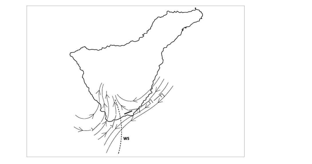
OROGRAPHICAL WIND SHEAR SITUATION OF LOW PRESSURE SYSTEM AT THE SURFACE (STORM), MAINLY AFFECTING RWY 25
In situations of low pressure affecting the islands, with synoptic wind SW-NW, the orographical wind shear pattern can be reversed, appearing on final approach to the RWY 25 below 1600 ft, with wind intensities on runway higher than 15 kt and SW-NW direction. The wind shear is usually positive and in the range of 15 to 30 kt. These situations may also generate gust fronts in the vicinity of the aerodrome, associated with convective activity.
AERONAUTICAL CHARTS RELATED TO AN AERODROMECHARTS RELATED TO THE AERODROME
The list of charts related to the aerodrome can be found on the link below:
VISUAL SEGMENT SURFACE (VSS) PENETRATION
The instrument approach procedures affected can be found below:
IAC 1 - RNP Z RWY 07 (LPV ONLY): LPV.
IAC 2 - RNP Y RWY 07: LNAV, LNAV/VNAV.
IAC 3 - ILS Z RWY 07: direct approach.
IAC 4 - ILS Y RWY 07: direct approach.
IAC 5 - LOC RWY 07: direct approach.
IAC 6 - VOR RWY 07: direct approach.
IAC 7 - RNP Z RWY 25 (LPV ONLY): LPV.
IAC 8 - RNP Y RWY 25: LNAV, LNAV/VNAV.
IAC 9 - ILS Z RWY 25: direct approach.
IAC 10 - ILS Y RWY 25: direct approach.
IAC 11 - LOC RWY 25: direct approach.
IAC 12 - VOR RWY 25: direct approach.