LEPA/LESJ AD 2 AERODROME DATA
AERODROME LOCATION INDICATOR AND -NAME
LEPA/LESJ - PALMA DE MALLORCA
AERODROME GEOGRAPHICAL AND ADMINISTRATIVE DATA
ARP |
393306N 0024420E. See AD 2-LEPA/LESJ ADC. |
|
Distance and direction from the city |
8 km E. |
|
Elevation |
8 m/27 ft. |
|
Geoid undulation |
48.98 m ± 0.10 m (1). |
|
Reference temperature |
31°C. |
|
Low average temperature |
9ºC. |
|
Magnetic variation |
1° E (2020). |
|
Annual change |
7.0' E. |
|
AD administration |
CIV: Aena. MIL: Ejército del Aire y del Espacio. |
|
Address |
CIV: Aeropuerto de Palma de Mallorca, 07611 Palma. MIL: Base Aérea de Son San Juan. Crta de Manacor s/n 07071 Palma |
|
TEL |
CIV: +34-971 789 000 MIL: +34-971 497 504 |
|
FAX |
CIV: +34-971 789 010/1/2 MIL: +34-971 497 605 |
|
AFTN |
CIV: LEPA MIL: LESJ |
|
CIV: pmi.sita@aena.es MIL: baseopsala49@mde.es |
||
SITA |
CIV: PMISITA |
|
Approved traffic |
IFR/VFR (2). |
|
Remarks |
(1) For all AD points. (2) VFR traffic is not accepted except for hospital, military, search and rescue and State flights from MAY 1st to OCT 31st from Friday to Sunday, HR: H24. AD closed for helicopter operations, with the exception of: ambulance, emergency and State flights, or flights servicing Autonomous Communities and other Local Bodies, provided these are non-commercial public services. |
OPERATIONAL HOURS
Airport |
H24 (1). |
|
Customs and Immigration |
H24. |
|
Health and Sanitation |
See GEN 1.4. |
|
AIS |
H24 (2). |
|
ARO |
H24 (3). |
|
OPV |
H24 |
|
Apron Management Service (SDP) |
H24, provided by ATS. |
|
MET briefing |
H24. |
|
ATS |
H24. |
|
Fuelling |
H24. |
|
Handling |
H24. |
|
Security |
H24. |
|
De-icing |
H24. |
|
Remarks |
(1) It is compulsory for foreign state/military aircraft to request PPR at least 72 hours in advance to:
(2) Centralised AIO Office - International NOTAM Office
(3) Service provided from the Operations Office of the airport. |
HANDLING SERVICES AND FACILITIES
Cargo facilities |
CIV: No limitations. MIL: 1 forklift (claw) up to 8000 Kg; 2 forklifts (claws) up to 4500 Kg. |
|
Fuel types |
CIV: JET A-1. MIL: F-34. |
|
Oil types |
MIL: G-354, G-395, H-573, H-542, O-156, O-1236, S-750, S-753. |
|
Refuelling capacity |
CIV: No limitations. MIL: Trucks: 40000 L; 22.5 L/s. Trucks: 20000 L; 16.66 L/s. |
|
De-Icing facilities |
Service provided by handling operator. Aircraft de-icing area on PRKG 104 to 109 and 114 to 118B. |
|
Hangar space |
No. |
|
Repair facilities |
CIV: Minor repairs by operating companies. |
|
Remarks |
MIL: GPU: AC (up to 100 KVA) and DC (up to 2500 A) units. Ramp agents: GROUNDFORCE
MENZIES AVIATION IBERICA
SWISSPORT HANDLING
Ramp agents may attend both commercial aviation and general aviation. General and Business Aviation Managers (FBO). For passengers and crew who opt to access through the General Aviation terminal, the General and Business Aviavion Managers (FBO) authorised by the airport are: AVIAPARTNER PALMA DE MALLORCA FBO S.A.
MALLORCAIR
Ramp agents for General and Business Aviation: AVIAPARTNER PALMA DE MALLORCA FBO S.A.
GENERAL AVIATION SERVICE GAS
GESTAIR
JETLAND EXECUTIVE SERVICES
MALLORCAIR
MELENDEZ
SKY VALET SPAIN
|
PASSENGER FACILITIES
Hotels |
MIL: Yes. |
|
Restaurant |
Yes. |
|
Transportation |
CIV: Buses and taxis. MIL: Vehicle subject to availability, on request (PPR). |
|
Medical facilities |
CIV: Ambulance service. MIL: First aid and ambulance. (1) |
|
Bank/Post Office |
Yes. |
|
Tourist information |
Yes. |
|
Remarks |
(1) HR 0730-1430 LT. |
RESCUE AND FIREFIGHTING SERVICES
Fire category |
CIV: 9. (1) MIL: 4. (2) |
|
Rescue equipment |
MIL and CIV: In accordance with the fire category published. |
|
Removal of disabled aircraft |
CIV: Available upon prior signing of the declaration of aircraft operator’s inability to remove them by its own means and exemption from liability for the airport management. (3) Capacities of the available equipment:
MIL: Towing tractor and aircraft rescue crane up to 30 TM. |
|
Remarks |
(1) The response time up to the furthest away point of the runways is less than 3 MIN, with an operational objective of 2 MIN. (2) Guaranteed attended service between 0730-1500 LT and out of HR for scheduled flights.
(3) Contact phone number for removal of disabled aircraft: Service Executive: +34-971 789 595. |
RUNWAY SURFACE CONDITION ASSESSMENT AND REPORTING, AND SNOW PLAN
Types of clearing equipment |
Urea spreader, snowplough. |
|
Clearance priorities |
Runways, rapid exit taxiways and runway access taxiways, taxiways, apron accesses and aprons. |
|
Use of material for movement area surface treatment |
Urea (UREA). |
|
Specially prepared winter runways |
Not applicable. |
|
Remarks |
Period of application of snow plan: 15-NOV to 31-MAR. Runway surface condition assessment and reporting in accordance with the Global Reporting Format (GRF) methodology described in AD 1.2.2. Aerodrome in service during all seasons of the year. |
APRONS, TAXIWAYS AND CHECK LOCATIONS/POSITIONS DATAMOVEMENT AREA DETAILS
Apron |
Surface: Concrete and asphalt. Strength:
PRKG:
East MIL apron: PCN 85/R/A/W/T. West MIL apron: PCN 71/R/A/W/T. |
|
Taxiways |
Width: 23 m, EXC:
Surface: Asphalt and concrete. Strength:
|
|
Check locations |
Altimeter: Apron: 4 m/14 ft. EXC PRKG 58, 60 and 62: 7m/24 ft. VOR: No. INS: See AD 2-LEPA/LESJ PDC. |
|
Remarks |
The geographical coordinates of the aircraft stands are available at AD 2-LEPA/LESJ PDC. TWY centre line: see INSIGNIA and Data Set. |
SURFACE MOVEMENT GUIDANCE AND CONTROL SYSTEM AND MARKINGSTAXIING GUIDANCE SYSTEM AND MARKINGS
Taxiing guidance system |
Runway-holding positions, intermediate holding position, stopbars, intermediate holding positions lights, lighted position indicators, NO ENTRY signs, arresting gear marking, runway guard lights, LGTD information and aircraft stands identification markings. (1) (2) |
|
RWY markings |
Designators, threshold, threshold displaced (RWY 24R and RWY 06R), centre line, side stripe, aiming point and touchdown zone with distance code. |
|
TWY markings |
Centre line, side stripe and reflective markers on edge, EXC N7: None. |
|
Remarks |
LED Lights: Intermediate holding positions, rapid exit taxiway lights, runway guard lights of H1, H2, H4, H6, H7 (Cat. II/III), H8 (Cat. II/III). (1) Exemption to the requirement related to taxiway centre line lights: In the TWY S2, the segment lights connecting the taxiing S2 and runway, are inset lights (full-flusht type) NOT visible during take-off and/or landing operations from distances greater than or close to100 m from them. (2) Types of visual docking guidance system in each stand are published in AD 2-LEPA/LESJ PDC. |
AERODROME OBSTACLES
| Obstacles which penetrate Approach, Take-Off Climb, Conical, Inner Horizontal, Transitional, Inner Transitional and Balked Landing Surfaces established in ICAO Annex 14; and the areas 2A and 3 established in ICAO Annex 15. Those penetrating these surfaces are identified in the CSV file as “Relevante_Relevant = Si/Yes”. | See Item 10 and Digital Data Set. section. | |
Remarks |
See AD 2-LEPA/LESJ AOC. Obstacles marked with red LED lights. There is the possibility that they are not visible with night vision glasses. |
METEOROLOGICAL INFORMATION PROVIDEDMETEOROLOGICAL SERVICE PROVIDED
MET office |
Palma de Mallorca EMAe. |
|
HR |
H24. |
|
METAR |
Half-hourly. |
|
TAF |
24 HR. |
|
TREND |
Yes. |
|
Briefing |
In person and by telephone. |
|
Flight documentation/Language |
Charts and plain language / Spanish. |
|
Charts |
Significant forecasted and wind and temperature in altitude maps. |
|
Supplementary equipment |
Clouds image, lightnings and radar information display. |
|
ATS unit served |
TWR, APP. |
|
Additional information |
Valencia OMAe (LEVA): H24
Palma de Mallorca EMAe: H24
|
|
Remarks |
Aerodrome climatological summary available. Aerodrome warnings available. There is, within the aerodrome vicinity, a meteorological station sited at 3936N 00242E. See ENR 5.3. |
RUNWAY PHYSICAL CHARACTERISTICS
RWY |
Direction |
DIM (m) |
THR PSN |
THR ELEV TDZ ELEV |
SWY (m) |
CWY (m) |
Strip (m) |
OFZ |
RESA (m) |
RWY/SWY SFC PCN |
|---|---|---|---|---|---|---|---|---|---|---|
06L (1) |
058.56°GEO 057°MAG |
3270 x 45 |
393249.75N 0024238.65E |
THR: 4.6 m / 15 ft TDZ: 4.6 m / 15 ft |
No |
60 x 150 |
3390 x 300 (6) |
No |
240 x 150 (6) |
RWY: ASPH PCN 80/F/A/W/T SWY: No |
24R (2) |
238.58°GEO 237°MAG |
3270 x 45 |
393343.85N 0024433.03E |
THR: 2.5 m / 8 ft TDZ: 2.5 m / 8 ft |
No |
60 x 150 |
3390 x 300 (6) |
No |
240 x 150 (6) |
RWY: ASPH PCN 80/F/A/W/T SWY: No |
06R (3) |
058.58°GEO 057°MAG |
3000 x 45 |
393235.47N 00024408.94E |
THR: 8 m / 25 ft TDZ: No |
No |
60 x 150 |
3120 x 300 (6) |
No |
240 x 150 (6) |
RWY: ASPH PCN 82/F/A/W/T SWY: No |
24L (4) |
238.60°GEO 237°MAG |
3000 x 45 (5) |
393319.24N 0024541.52E |
THR: 2.4 m / 8 ft TDZ: 2.4 m / 8 ft |
No |
No |
3120 x 300 (6) |
Yes |
240 x 150 (6) |
RWY: ASPH PCN 82/F/A/W/T SWY: No |
Remarks: (1) RWY 06L end coordinates: 393345.02N 0024435.52E. (2) THR RWY 24R displaced 70 m. (3) THR RWY 06R displaced 410 m. (4) RWY 24L end coordinates: 393228.51N 0024354.25E. (5) RWY 24L: Last 410 m of runway paved and suitable for aircraft to stop in case of an abandoned take-off. (6) Grass soil. |
||||||||||
Profile
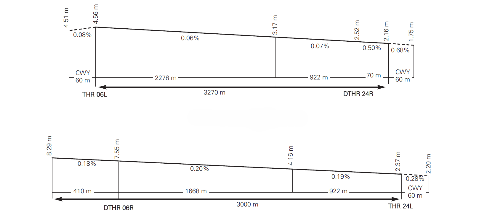
DECLARED DISTANCES
RWY |
TORA (m) |
TODA (m) |
ASDA (m) |
LDA (m) |
|---|---|---|---|---|
06L |
3270 |
3330 |
3270 |
3270 |
24R |
3270 |
3330 |
3270 |
3200 |
06R |
3000 |
3060 |
3000 |
2590 |
24L |
2590 (1) |
2590 (1) |
3000 (1) |
3000 |
06L INT N6 |
2460 |
2520 |
2460 |
– |
24R INT N1 |
2750 |
2810 |
2750 |
– |
06R INT H7 |
2812 |
2872 |
2812 |
– |
06R INT H8 |
2680 |
2740 |
2680 |
– |
06R INT S3 |
2390 |
2450 |
2390 |
– |
Remarks: (1) Last 410 m of runway paved and suitable for aircraft to stop in case of an abandoned take-off. |
||||
APPROACH AND RUNWAY LIGHTING
Runway |
06L |
|
Approach |
Precision CAT I, 900 m. LIH. |
|
PAPI (MEHT) |
3° (16.19 m / 53 ft) (1). |
|
Threshold |
Green with wing bars (1). |
|
Touchdown zone |
No. |
|
Runway centre line |
3270 m: 2370 m white+600 m red and white+300 m red. LIH. Distance between lights: 15 m (1). |
|
Runway edge |
3270 m: 2670 m white + 600 m yellow. LIH. Distance between lights: 60 m (1). |
|
Runway end |
Red (1). |
|
Stopway |
No. |
|
Remarks |
(1) LED lightling. |
Runway |
24R |
|
Approach |
Precision CAT I, 900 m. LIH. Threshold identification lights (1). |
|
PAPI (MEHT) |
3° (18.52 m / 61 ft) (1). |
|
Threshold |
Green with wing bars (1). |
|
Touchdown zone |
No. |
|
Runway centre line |
3270 m: 2370 m white+600 m red and white+300 m red. LIH. Distance between lights: 15 m (1). |
|
Runway edge |
3270 m: 70 m red + 2600 m white + 600 m yellow. LIH. Distance between lights: 60 m (1). |
|
Runway end |
Red (1). |
|
Stopway |
No. |
|
Remarks |
(1) LED lightling. |
Runway |
06R |
|
Approach |
Threshold identification lights. |
|
PAPI (MEHT) |
3.4° (16.52 m / 54 ft) (1). |
|
Threshold |
Green with wing bars (2). |
|
Touchdown zone |
No. |
|
Runway centre line |
3000 m: 2100 m white+600 m red and white+300 m red. LIH. Distance between lights: 15 m (2) (3). |
|
Runway edge |
3000 m: 410 m red + 1990 m white + 600 m yellow. LIH. Distance between lights: 50 m. |
|
Runway end |
Red (2). |
|
Stopway |
No. |
|
Remarks |
(1) PAPI bar situated on the right side of the runway. (2) LED lightling. (3) Exemption to the requirement related to runway centre line lights: On RWY 06R, starting at 475 m from threshold, there is a segment of 285 m of inset runway centre line lights (full-flush type) NOT visible during take-off and/or landing operations from distances greater than or close to 100 m from them. |
Runway |
24L |
|
Approach |
Precision CAT II/III, 900 m, LIH. |
|
PAPI (MEHT) |
3° (16.95 m / 56 ft). |
|
Threshold |
Green with wing bars (1). |
|
Touchdown zone |
900 m white (1). |
|
Runway centre line |
3000 m: 2100 m white+600 m red and white+300 m red. LIH. Distance between lights: 15 m (1). |
|
Runway edge |
3000 m: 2400 m white + 600 m yellow. LIH. Distance between lights: 50 m. |
|
Runway end |
Red (1). |
|
Stopway |
No. |
|
Remarks |
Rapid exit taxiway indicator lights (S1 and S2) (1). (1) LED lightling. |
OTHER LIGHTING, SECONDARY POWER SUPPLY
ABN/IBN |
No. |
|
WDI |
1 near THR 06L, 1 near THR 06R, 1 near THR 24L, 1 near THR 24R. LGTD. 1 near West military apron not LGTD. |
|
TWY lighting |
Centre line (1). MU without lighting. |
|
Apron lighting |
CIV: Floodlighting poles. MIL: Blue lights of apron limit. Floodlighting poles. Available on request (PPR). |
|
Secondary power supply |
Generators that provide a maximum switch-over (light) time of 1 second for the following systems: runway centre line, runway end and stop bars, and a maximum of 15 seconds for the rest of the lighting systems, according to Annex 14. |
|
Remarks |
(1) LED lighting. |
HELICOPTER LANDING AREA
Position |
|
|
Elevation |
|
|
Dimensions, surface, maximum weight, marking |
Dimensions of MAX ACFT: see PDC. Strength: see item 8. |
|
Direction |
No. |
|
Declared distances |
(**) See table. |
|
Lighting |
See item 14. |
|
Remarks |
See item 20, local regulations, helicopter operations. |
(*)
PRKG |
ELEV (m) |
|---|---|
301 |
3.7 |
308 |
3.7 |
309 |
3.7 |
310 |
3.6 |
(**)
TORA (m) |
TODAH (m) |
RTODAH (m) |
LDAH (m) |
|
|---|---|---|---|---|
06L INT N7 (1) |
2945 |
3005 |
2945 |
– |
24R INT N7 (1) |
250 |
310 |
250 |
– |
(1) TWY N7 for take-off from intersection exclusively for helicopters in air taxiing. |
||||
AIR TRAFFIC SERVICES AIRSPACE ATS AIRSPACE
Designation |
CTR PALMA DE MALLORCA. |
|
Lateral limits |
393207.0N 0022956.0E; 393335.0N 0023307.0E; 393433.0N 0023827.0E; 393359.0N 0023853.0E; 393645.0N 0024450.0E; 393755.9N 0024355.9E; 394254.0N 0024626.4E; 394534.8N 0025212.0E; 393119.1N 0030322.6E; 392002.1N 0023914.5E; 393207.0N 0022956.0E. |
|
Vertical limits |
SFC - 4500 ft AMSL (1). |
|
Airspace class |
D (1). |
|
Unit Language |
PALMA APP. ES/EN. |
|
Transition altitude |
1850 m / 6000 ft. |
|
Hours of applicability |
- |
|
Remarks |
(1) Except VFR corridors (See ENR 2.1). |
Designation |
ATZ PALMA. |
|
Lateral limits |
Area defined by 393358N 0023851E, CW arc of 8 KM radius centred on ARP LEPA/LESJ up to 393715N 0024554E, 393358N 0023851E (2). |
|
Vertical limits |
1500 ft AMSL - 2500 ft AMSL (3). |
|
Airspace class |
D (1). |
|
Unit Language |
PALMA TWR. ES/EN. |
|
Transition altitude |
- |
|
Hours of applicability |
- |
|
Remarks |
(1) Except VFR corridors (See ENR 2.1). (2) Or the ground visibility, whichever is lower. (3) Or up to the cloud ceiling, whichever is lower. |
Designation |
ATZ PALMA. |
|
Lateral limits |
Area defined by 393358N 0023851E, CCW arc of 8 KM radius centred on ARP LEPA/LESJ up to 393715N 0024554E, 393358N 0023851E (2). |
|
Vertical limits |
SFC - 2500 ft AMSL (3). |
|
Airspace class |
D (1). |
|
Unit Language |
PALMA TWR. ES/EN. |
|
Transition altitude |
- |
|
Hours of applicability |
- |
|
Remarks |
(1) Except VFR corridors (See ENR 2.1). (2) Or the ground visibility, whichever is lower. (3) Or up to the cloud ceiling, whichever is lower. |
AIR TRAFFIC SERVICES COMMUNICATION FACILITIESATS COMMUNICATION FACILITIES
Service |
Call sign |
FREQ |
HR |
Remarks |
|---|---|---|---|---|
APP |
Palma Control
|
118.955 C |
H24 |
APP/I |
118.005 C |
HX |
APP/l |
||
| TAR | Palma Control |
119.155 C |
H24 |
APP/L |
| SSR/SRE | Palma Control
|
119.405 C |
H24 |
APP/L |
355.400 MHz |
O/R |
APP/MIL |
||
TWR |
Palma TWR |
118.305 C |
H24 |
LOCAL ARR |
118.455 C |
H24 |
LOCAL DEP |
||
121.500 MHz |
H24 |
EMERG |
||
121.605 C |
H24 |
BACK-UP |
||
121.705 C |
H24 |
GMC South |
||
121.905 C |
H24 |
GMC North |
||
122.100 MHz |
H24 |
MIL |
||
123.880 C |
(1) |
CLR. (1) Activity announced by ATIS. |
||
125.830 C |
H24 |
BACK-UP |
||
243.000 MHz |
H24 |
EMERG |
||
257.800 MHz |
H24 |
MIL |
||
ATIS |
Palma de Mallorca Information |
119.255 C |
H24 |
ARR |
121.780 C |
H24 |
DEP |
||
D-ATIS |
Palma de Mallorca Information |
NIL |
H24 |
Provision of ATIS information via data link. |
OPS |
Palma operaciones |
130.250 MHz |
H24 |
Coordination of airport services. This frequency coordinates the apron services, provides information about slots and flight plans and conducts monitoring of arriving and departing flights at Son Bonet AD. |
INFO (MIL) |
Palma (MIL) |
165.275 MHz |
H24 |
Coordination of military airport services. This frequency coordinates military apron services, provides information and flight plans. |
RADIO NAVIGATION AND LANDING AIDSRADIO NAVIGATION & LANDING FACILITIES
| Facility (VAR) | ID | FREQ | HR | Coordinates | ELEV DME | Remarks |
|---|---|---|---|---|---|---|
| DVOR (1ºE) | MJV | 113.300 MHz | H24 | 392606.7N 0024529.9E | - | COV 40 NM AVBL BTN:
|
| DME | MJV | CH 80X | H24 | 392606.7N 0024529.2E | 150 m | COV 40 NM AVBL BTN:
R-344 at:
R-048 at:
|
| DVOR (2ºE) | CDP | 112.900 MHz | H24 | 394151.7N 0032603.7E | - | R-248 COV AVBL:
|
| DME | CDP | CH 76X | H24 | 394151.2N 0032602.6E | 240 m | R-248 COV AVBL:
|
| DVOR (1ºE) | POS | 116.400 MHz | H24 | 395538.8N 0030652.5E | - | R-256 at:
COV 40 NM AVBL BTN:
|
| DME | POS | CH 111X | H24 | 395539.7N 0030653.5E | 360 m | R-256 at:
COV 40 NM AVBL BTN:
|
| DVOR (1ºE) | JOA | 117.700 MHz | H24 | 393352.9N 0024447.9E | - | COV 40 NM AVBL BTN:
|
| DME | JOA | CH 124X | H24 | 393353.4N 0024447.9E | 0 m | COV 40 NM AVBL BTN:
|
| NDB (1ºE) | ADX | 384.000 kHz | H24 | 393258.0N 0022345.1E | - | COV 30 NM. COV 7 NM: possible oscillations of more than 10º BTN 360º/100º at 4500 ft AMSL. |
| NDB (1ºE) | CST | 351.000 kHz | H24 | 393829.0N 0025456.3E | - | At 10 NM, possible oscillations greater than ±10º BTN 319º/349º at 7000 ft AMSL. At 25 NM, possible oscillations greater than ±10º BTN 072º/092º and 330º/352º at 6000 ft AMSL. |
| NDB (2ºE) | PTC | 401.000 kHz | H24 | 392538.4N 0031524.2E | - | COV 30 NM. |
| LOC 06L (1ºE) ILS CAT I | PLM | 110.900 MHz | H24 | 393350.3N 0024446.6E | - | 057° MAG / 379 m FM THR 24R. COV 17 NM at 3000 ft AVBL BTN 33º to the left & 35º to the right FM RCL. |
| GP 06L | 330.800 MHz | H24 | 393259.7N 0024247.6E | - | 3°; RDH 15.7 m; at 342 m FM THR 06L & 151 m FM RCL to the left in direction APCH. COV 10NM at 1900 ft AVBL BTN 6º to the left & 8º to the right FM RCL. |
|
| ILS/DME 06L | PLM | CH 46X | H24 | 393259.7N 0024247.6E | 9 m | REF DME THR 06L. |
| LOC 24L (1ºE) ILS CAT II/III | IPAL | 109.300 MHz | H24 | 393223.3N 0024343.3E | - | 237° MAG / 718 m FM THR 06R. COV 17 NM LOC (15.4 DME) AVBL BTN -35º & +26º FM RCL at 2100 ft AMSL or ABV. COV 25 NM LOC (23.4 DME) AVBL BTN ±10º RCL at 3500 ft AMSL or ABV. |
| GP 24L | 332.000 MHz | H24 | 393310.0N 0024534.2E | - | 3°; RDH 16.30 m; at 298 m FM THR 24L & 153 m FM RCL to the left in direction APCH. | |
| ILS/DME 24L | IPAL | CH 30X | H24 | 393309.8N 0024534.3E | 15 m | REF DME THR 24L. COV 17 NM LOC (15.4 DME) AVBL BTN -29º & +18º FM RCL at 2100 ft AMSL or ABV. |
| LOC 24R (1ºE) ILS CAT I | PAA | 109.900 MHz | H24 | 393244.5N 0024227.5E | - | 237° MAG / 310 M FM DTHR 06L. COV 17 NM LOC (15.5 DME) AVBL BTN ±35º RCL at 6000 ft AMSL or ABV. COV 25 NM LOC (23.4 DME) AVBL BTN ±10º RCL at 4500 ft AMSL or ABV. |
| GP 24R | 333.800 MHz | H24 | 393342.2N 0024417.2E | - | 3°; RDH 18 m; at 350 m FM DTHR 24R & 152 m FM RCL to the right in direction APCH. Full fly-up indications may not be received BLW GP beyond 5º to the right FM RCL. |
|
| ILS/DME 24R | PAA | CH36X | H24 | 393342.2N 0024417.2E | 9 m | REF DME DTHR 24R. |
| NDB (1ºE) | PA | 307.500 kHz | H24 | 393557.7N 0024916.2E | - | 057° MAG / 7917 m FM DTHR 24R. At 15 NM, signal oscillations greater than ±10º BTN 269º/289º, 011º/014º and on 339º. At 7 NM, oscillations greater than ±10º BTN 320º/005º. 212º & 238º possible signal loss. |
| TACAN (1ºE) | SSJ | CH 21X | H24 | 393334.9N 0024359.7E | - | U/S FM 40 NM at:
|
LOCAL AERODROME REGULATIONSLOCAL REGULATIONS
AIRPORT REGULATION
RESTRICTIONS TO OPERATIONS
From May 1st until October 31st, the use of the airport will be restricted for aircraft with a cruising speed lower than 220 kt (except State, hospital and search and rescue aircraft), daily from 0530 to 0700 and 1600 to 1830.
If any affected aircraft requires the use of the airport during these periods, it shall assume the possible delays, as not restricted aircraft will always have priority.
Due to General Aviation apron limited capacity, from April 1st until September 30th, all the General Aviation and Corporative Aviation traffics which want to operate in the airport, must include in their messages or request for slot the data corresponding to the arrival and the departure flights. The slot request shall be understood as not authorized until the reception of the confirmed coordination. The coordination request must include: aircraft registration number, ICAO code, length and wingspan.
From 01 June until 30 September, the maximum parking time on the general aviation apron for an aircraft over 20 m in length shall be 7 days, unless expressly authorised by the airport.
In case of lack of capacity in the apron, it should may coordinate flights with a maximum stay of 3 hours, in order to unload passengers and refuelling of the aircraft, but at least one member of the crew shall stay inside the aircraft.
Flights without previous coordination requested, shall be coordinated on arrival, subject in every case to the capacity available.
In the event of apron capacity problems, if, upon the arrival of a General and Business Aviation flight, there are discrepancies (time, aircraft type, date of operation) with respect to the slot cleared, Palma de Mallorca airport reserves the right to deny the stay coordinated and authorise only three hours. In this case, the crew will not be able to leave the aircraft until it departs.
Changes to coordination required by a change of airline designator shall be requested directly from the operations centre of the airport, and prior to the arrival of the flight in question.
See section 1.3.1.7 of AD 1.1 regarding coordination with airlines for emergency management.
DIVERTING
All flights which, by any cause, deviate to the airport, shall notify the cause of this matter to the Air Navigation Services whom, in turn, will transmit it to CEOPS of the airport.
GENERAL AVIATION AND BUSINESS
It is mandatory to contract handling agent for all operation to General and Business Aviation, by virtue of provisions in item 3.1.6 of AD 1.1 of the AIP-Spain.
FOREIGN STATE AIRCRAFT
PPR must be requested at least 72 hours in advance in all cases.
TRANSPORT OF LIVE ANIMALS
To guarantee compliance with the Regulation (EU) No 576/2013 of the European Parliament and of the Council of 12 June 2013 on the non-commercial movement of pet animals and repealing Regulation (EC) No 998/2003, any Air Carrier wishing to operate at the Airport and transport the animals (pets) set out in part A of Annex I to the cited Regulation (dogs, cats and ferrets) in the cabin, as part of passenger hand baggage, must have engaged a handling agent who is to be responsible for handling the same in those cases where, during the checks undertaken by the Resguardo Fiscal of the Guardia Civil or Customs Personnel of the Passenger Terminals of Palma de Mallorca Airport, some breach of the health requirements established in the cited regulations is detected, prompting the animal's rejection at the point of entry.
The management for animals rejected at the border shall include, at least, transport to the facilities of the Border Inspection Service at the appropriate cargo terminal, their subsistence, veterinary care and animal welfare, and even their return to origin within the periods stipulated by the public health authorities.
GROUND MOVEMENT
Collision avoidance with other aircraft or obstacles is a responsibility of:
-
Pilots taxiing in the apron and in the area not visible from TWR.
-
Handling companies during push-back manoeuvring or exiting the stand.
APRON
-
It is forbidden to cross the taxiways in the apron on foot. Access to the aircraft on foot will only be possible if parked in a stand next to the terminal building. Access to the rest of stands shall be made by vehicle.
-
On every stand equipped with 400 Hz system supply:
-
It is mandatory the use of the 400 Hz system.
-
Terminal contact stands:
The use of aircraft APU (Auxiliary Power Unit) is forbidden for the period with 2 minutes after blocks-on for arrivals and 6 minutes before the departure TOBT, except for wide-body aircraft, which are allowed to use it 5 minutes after in-block upon arrival and until 10 minutes before TOBT. The aircraft APU (Auxiliary Power Unit) will only be used when neither the 400 Hz system nor the mobile units are operative, or when the air conditioning service is required and it is not available.
-
The use of a harness hook is recommended for fastening of the 400 Hz hosepipe of the system to the aircraft. Otherwise, the airport authority will not accept responsibility for any damages the aircraft could suffer.
-
Remote stands:
Use of the aircraft APU is prohibited during the period between 10 minutes after in-block upon arrival and 10 minutes before the departure TOBT, except for wide-body aircraft, which are allowed to use it from 15 minutes after in-block upon arrival until 50 minutes before departure. The APU (Auxiliary Power Unit) of the aircraft may only be used when the mobile units are not available.
-
-
When it is necessary to connect the 400 Hz system before an aircraft turn off the engines, either due to the aircraft APU (Auxiliary Power Unit) is not operational or a company procedure with prior permission of the airport authority:
-
The flight coordinator shall ascertain that the aircraft is totally stopped and confirm it by means of signals with the pilot in charge of the aircraft (RCA, Appendix C, Adjunct 5) before the blocks will be on.
-
Any operation shall not be carried out until the blocks will be on.
-
-
On the remote stands without 400 Hz system, the use of APU (Auxiliary Power Unit) is forbidden during the night hours, (see item 21), except for aircraft cleared to start-up engines and taxiing.
START-UP PROCEDURE
Aircraft may request ATC authorization from 30 minutes prior to their TOBT, and may request start-up:
-
from 5 minutes prior to TOBT up to TOBT for flights regulated with CTOT,
-
from 5 minutes prior to TOBT up to 5 minutes after for other flights.
The aircraft on first call must provide the following information:
-
Report the type and series of aircraft, aircraft stand and the ATIS message received,
-
Communicate the need to perform a cross-bleed start if required,
-
Report any possible restrictions in complying with local regulations (RNAV equipment, take-off performance, etc.).
ATC Authorization will only be issued between TOBT -30 minutes and TOBT -5 minutes.
If possible, Palma Clearance will transfer traffic to GMC in order to request start-up and push-back / taxiing on the same frequency between TOBT -5 and TOBT +5. If this is not possible, a start-up request will be recorded in the A-CDM system and TSAT information will be provided. The start-up request log is equivalent to the REA message request for flights regulated with CTOT.
In case of non-compliance with A-CDM parameters, ATC will not record the request for start-up and the pilot should contact his flight coordinator to correct A-CDM parameters. Palma Clearance will not provide information about non-compliance of the A-CDM process to avoid frequency overload.
Once the start-up request has been recorded and TSAT information has been provided, in order to avoid saturating the CLR frequency, pilots will refrain from making successive calls before receiving the call from Palma Clearance.
If Palma Clearance does not receive a start-up request within 5 minutes after TOBT has been given, the flight will lose its TSAT and its request will not be authorized. It will be required to receive a new updated TOBT and EOBT so that the flight can be sequenced again and receive a new TSAT. The TOBT and / or EOBT update can only be done by the airline or its ground handling agent, so pilots will refrain from making requests to ATC in this regard.
The start-up and push-back request should be made on the corresponding GMC frequency, and should start within 5 minutes from the transfer to the GMC frequency. Authorization for push-back can only be given by GMC.
The push-back maneuver may not be performed without the express authorization of GMC.
For start-up manoeuvres with GPU or external APU, the aircraft should request authorization for cross-bleed start in addition to pushback authorization at ground control radio frequency and subsequently start up one engine, perform the pushback manoeuvre (or autonomous output) maintaining idle engine power until positioned on the apron taxiway, and then the power can be increased in order to start up the rest of the engines, strictly as necessary.
When starting engines at idling speed, the boarding bridge must always be disconnected.
ATC AUTHORIZATION REQUEST AND START-UP VIA DATA LINK
At Palma de Mallorca Airport, procedures for departure are applied via Data Link (DCL) for ATC authorization services.
In case of discrepancies, voice communications will always prevail over data link.
The pilot may request ATC authorization by DCL in accordance with the start-up procedures (See AD2 item 20, 2.2) with a maximum of 30 minutes before the TOBT (CDM mode) or EOBT (without CDM).
-
The pilot must request ATC and S/U authorization together via RCD. The RCD message (Departure Clearance Request) must contain the following information:
-
Aircraft callsign in accordance with the filed flight plan (FPL).
-
Aerodrome of origin.
-
Aircraft stand.
-
Destination aerodrome.
-
Letter corresponding to the ATIS information received.
-
ICAO aircraft type designator.
Any free text sent via the RCD by the pilot will not be considered by the ATC. Special requests will always be made via voice command.
-
-
The pilot will receive a message acceptance "RCD RECEIVED" or cancellation "RCD REJECTED".
-
When communicating approval, Palma Clearance will issue a CLD message with the following fields:
-
Aircraft callsign.
-
Destination aerodrome.
-
Assigned runway for departure.
-
Take-off procedure (SID).
Note: The initial altitude will correspond to the published SID.
-
SSR code mode A (SQUAWK).
-
ADT (Approved Departure Time).
Note: ADT = CTOT of the flight, if applicable.
-
Next frequency.
-
Current ATIS information letter.
-
Additional information, including instructions on contacting GMC for start-up clearance or instructions to request it in case of failure to comply with the start-up approval parameters indicated in AD 2, Item 20, 2.2.
-
-
When a CLD message is sent in the valid range of TOBT and TSAT, ATC clearance and and instructions on contacting GMC will be received. If not ready for start-up, the pilot must not accept the frequency change and will either send a new message or contact via voice communications to the CLR controller when ready.
-
When an FSM message of the type "REVERT TO VOICE PROCEDURES" is received, communication via data link will be terminated and must be reverted to voice procedures.
-
When a CLD message is received, the pilot:
-
If any inconsistencies in the received message are detected, the pilot must revert to voice procedures and request a new authorization.
-
If the pilot considers the authorization CLD message to be correct, he/she must respond via data link with a CDA message (Departure Clearance Echoback).
-
-
If a CDA message is not received by the pilot within the waiting time, or a CDA that is inconsistent with the previous CLD message is received, communication via data link will be terminated and a "CDA REJECTED" message will be received in the FMS.
-
When the correct CDA message is received, the ATC system will send the aircraft a "CLEARANCE CONFIRMED" message in the FMS and will terminate the communication via data link.
The request for start-up and push-back must be requested the corresponding GMC frequency and initiated within 5 minutes from the transfer to the GMC frequency. Authorization for push-back can only be given by GMC.
REVERT TO VOICE PROCEDURES
Upon receiving a message of the type "REVERT TO VOICE PROCEDURES", or in the event of any inconsistency in the authorization received, the pilot will contact via voice command with the controller and request a new authorization.
Push and hold manoeuvre When an aircraft has a long duration SLOT, the pilot may request a "Push and Hold" to the handling agent. The Airport Operations Coordination Centre (CEOPS) will contact TWR to communicate the possibility of a push and hold manoeuvre for the aircraft indicating the available parking, and TWR will transmit the information to the flight crew. The aircraft may move to the remote parking stand under its own power or by dragging. When parked, it may keep the engines running, with signalling by means of three cones in front of the aircraft, or it may switch the engines off, in which case no signalling is required. When exiting, the pilot shall notify TWR. TWR will notify the Signalman to review FOD on the parking stand and review the exit by the aircraft.
Possible remote parking stands for this manoeuvre are: PRKG 114B and 118B (autonomous). Only Category C aircraft. Only with Configuration 24.
TAXIING PROCEDURES
To optimise apron management at times of high traffic demand, a zone called GMC-C is defined (see the PDC chart for more detail), which will be managed at different times either by GMC-N or GMC-S.
- DEPARTING AIRCRAFT
Pilots shall contact the corresponding Palma Ground (GMC, GMC-N, GMC-S) (see item 18) to request permission for towed push-back and/or taxiing.
The aircraft must be ready to be pushed back by towing or taxiing no later than 5 minutes after the time transferring to the GMC frequency. In case of autonomous positions, they must be ready for start-up at the time of transfer to GMC, and ready for taxiing within 5 minutes of the GMC approved start-up time. Otherwise the pilot must notify ATC.
Whenever an incorrect push-back of aircraft is detected, GMC will request the pilot to park the aircraft in the initial position again.
Whenever the pilot wishes to request a push-back that does not follow any of the published procedures, should contact the corresponding GMC who will send a “FOLLOW ME” vehicle to oversee the operation.
GMC may approve the published push-back corresponding to the opposite configuration to the runway in use, reporting the pilot which direction has to nose to.
The use of the reverse power is forbidden in the whole apron for the backward operation.
- ARRIVING AIRCRAFT
If no taxiing instructions are received, aircraft shall hold position short of the NORTH/SOUTH TWY after vacating the runway and expect ATC taxiing instructions in order to continue taxiing up to the parking position.
When GMC-N and GMC-S are operational, if the aircraft does not manage to establish communication with the GMC to which it has been transferred, it shall hold at the first intermediate holding position along its taxiing route.
Guidance by a “FOLLOW ME” vehicle will only be provided to General Aviation stands and those which visual docking guidance system is U/S.
Guidance service will also be provided on TWR or pilot's request or in exceptional cases.
Aircraft taxiing to the PRKG between 30 and 48, shall entry, preferably, by TWY V1 and hold short of the intermediate holding position.
ATC will authorize, whenever possible, the direct entry to those parking positions by TWY V2.
It is very important that before going to the apron aircraft pay special attention to the traffic on the taxiways. Aircraft taxiing on the apron shall do so at a speed that provides sufficient reaction time to prevent hard braking. In the service roads next to GATE F, G, K and M as specially critical areas where aircraft must pay special attention to traffic speed because aircraft has the appropriate speed to stop in a safe way for any circumstance which occurs during its course.
STANDARD TAXIING ROUTES
EAST CONFIGURATION
- ARRIVALS BY RWY 06L
-
R-1 to R-6, R-7 (stands 24, 25 and 114 to 117): Standard route (N3, N2, N1 or runway end, TWY NORTH).
-
PRKG 02-06B, 100-102, 103: STANDARD C (N3, N2, N1 or end of runway, TWY NORTH, GATE C), TWY LD.
-
PRKG 08-22: STANDARD D (N3, N2, N1 or end of runway, TWY NORTH, GATE D), TWY LE.
-
PRKG 23A-25, 114-117: STANDARD E (N3, N2, N1 or end of runway, TWY NORTH, GATE E), TWY LF.
-
PRKG 103B: STANDARD D (N3, N2, N1 or end of runway, TWY NORTH,GATE D).
-
PRKG 104-109: STANDARD E (N3, N2, N1 or end of runway, TWY NORTH, GATE E), TWY W5.
-
PRKG 301 (helicopters): see item 20, Local regulations, Helicopter operations.
-
PRKG 303 (airplanes), 306 (code letter E aircraft or lower), 307-10: STANDARD A (N3, N2, N1 or end of runway, TWY NORTH, GATE A), TWY LA.
-
PRKG 306 (code letter F aircraft): see item 20, Local regulations, Code letter F aircraft operations.
-
PRKG 311-315: STANDARD A (N3, N2, N1 or end of runway, TWY NORTH, GATE A), TWY LB.
-
PRKG 316-318: STANDARD B (N3, N2, N1 or end of runway, TWY NORTH, GATE B), TWY LC.
-
-
R-7 (PRKG 118-118B, 26, 119): STANDARD F (N3, N2, N1 or end of runway, TWY NORTH, LINK, GATE F), TWY LF.
-
PRKG 118 (code letter F aircraft): see item 20, Local regulations, Code letter F aircraft operations.
-
-
R-8 to R-11: Standard route: N3, N2, N1 or end of runway, TWY NORTH, LINK.
-
PRKG 27-29, 120-121: STANDARD F (N3, N2, N1 or end of runway, TWY NORTH, LINK, GATE F), TWY LF, LG.
-
PRKG 30-36 STANDARD G (N3, N2, N1 or end of runway, TWY NORTH, LINK, GATE G), TWY LG, V1.
-
PRKG 38-48: STANDARD G (N3, N2, N1 or end of runway, TWY NORTH, LINK, GATE G), TWY LG, V1, V2; or, prior ATC clearance, STANDARD G (N3, N2, N1 or end of runway, TWY NORTH, LINK, GATE G), TWY LG, V2.
-
PRKG 50-54: STANDARD G (N3, N2, N1 or end of runway, TWY NORTH, LINK, GATE G), TWY LJ.
-
PRKG 56-58: STANDARD J (N3, N2, N1 or end of runway, TWY NORTH, LINK, GATE J), TWY LK.
-
PRKG 123B: STANDARD G (N3, N2, N1 or end of runway, TWY NORTH, LINK, GATE G), TWY LG.
-
-
R-13 to R-17: Standard route: N3, N2, N1 or end of runway, TWY NORTH, LINK, SOUTH.
-
PRKG 60-68: STANDARD M (N3, N2, N1 or end of runway, TWY NORTH, LINK, SOUTH, GATE M), TWY T1.
-
PRKG 72: STANDARD M (N3, N2, N1 or end of runway, TWY NORTH, LINK, SOUTH, GATE M), TWY T1 o T2.
-
PRKG 80-86: STANDARD M (N3, N2, N1 or end of runway, TWY NORTH, LINK, SOUTH, GATE M), TWY T2.
-
PRKG 88-96: STANDARD M, (N3, N2, N1 or end of runway, TWY NORTH, LINK, SOUTH, GATE M), TWY LP.
-
PRKG 98-154B: STANDARD P (N3, N2, N1 or end of runway, TWY NORTH, LINK, SOUTH, GATE P), TWY LQ.
-
PRKG 155-159: STANDARD Q (N3, N2, N1 or end of runway, TWY NORTH, LINK, SOUTH, GATE Q), TWY LY.
-
General aviation PRKG 200-225: STANDARD Q (N3, N2, N1 or end of runway, TWY NORTH, LINK, SOUTH, GATE Q), TWY Y3.
-
General aviation PRKG 227-230: STANDARD Q (N3, N2, N1 or end of runway, TWY NORTH, LINK, SOUTH, GATE Q), TWY LY.
-
General aviation PRKG 231-241: STANDARD Q (N3, N2, N1 or end of runway, TWY NORTH, LINK, SOUTH, GATE Q), TWY LY, Y2.
-
General aviation PRKG 242-247: STANDARD Q (N3, N2, N1 or end of runway, TWY NORTH, LINK, SOUTH, GATE Q), TWY LY, Y1.
-
-
East military apron: N3, N2, N1 or runway end and TWY NORTH.
- West military apron: N3, N2, N1 or runway end and TWY NORTH.
- DEPARTURES BY RWY 06R
-
R-1 to R-7:
-
PRKG 02-06B, 100-103B: STANDARD F 06R (TWY LD,...LF, GATE F, TWY LINK, SOUTH, runway-holding positions H6, H7 or H8).
-
PRKG 08-22, 104-109: STANDARD F 06R (TWY LE, LF, GATE F, TWY LINK, SOUTH, runway-holding positions H6, H7 or H8).
-
PRKG 23A-26, 114-118B (code letter E aircraft or lower), 119: STANDARD F 06R (TWY LF, GATE F, TWY LINK, SOUTH, runway-holding positions H6, H7 or H8).
-
PRKG 301 (helicopters): see item 20, Local regulations, Helicopter operations.
-
PRKG 303 (aircraft), 306 (code letter E aircraft or lower), 307-310: STANDARD F 06R (TWY LA,…LF, GATE F, TWY LINK, SOUTH, runway-holding positions H6, H7 or H8).
-
PRKG 306, 118 (code letter F aircraft): see item 20. Local regulations, Code letter F aircraft operations.
-
PRKG 311-315: STANDARD F 06R (TWY LB,...LF, GATE F, TWY LINK, SOUTH, runway-holding positions H6, H7 or H8).
-
PRKG 316-318: STANDARD F 06R (TWY LC,...LF, GATE F, TWY LINK, SOUTH, runway-holding positions H6, H7 or H8).
-
-
R-8 to R-11:
-
PRKG 27-29, 120-123B: STANDARD G 06R (TWY LG, GATE G, TWY LINK, SOUTH, runway-holding positions H6, H7 or H8).
-
PRKG 30-48: STANDARD G 06R (TWY V2, LG, GATE G, TWY LINK, SOUTH, runway-holding positions H6, H7 or H8).
-
PRKG 50: STANDARD G 06R (TWY LJ, GATE G, TWY LINK, SOUTH, runway-holding positions H6, H7 or H8).
-
PRKG 52-58: STANDARD K 06R (TWY LJ, LK, GATE K, TWY SOUTH, runway-holding positions H6, H7 or H8).
-
-
R-13 to R-17:
-
PRKG 60-62: STANDARD M 06R (TWY T1, GATE M, TWY SOUTH, runway-holding positions H6, H7 or H8).
-
PRKG 64-68: STANDARD M 06R (TWY T1, T2, GATE M, TWY SOUTH, runway-holding positions H6, H7 or H8).
-
PRKG 72: STANDARD M 06R (TWY T1 or T2, GATE M, TWY SOUTH, runway-holding positions H6, H7 or H8).
-
PRKG 80 and 82: STANDARD M 06R (TWY T2, T1, GATE M, TWY SOUTH, runway-holding positions H6, H7 or H8).
-
PRKG 84 and 86: STANDARD M 06R (TWY T2, GATE M, TWY SOUTH, runway-holding positions H6, H7 or H8).
-
PRKG 88-96: STANDARD P 06R (TWY LP, GATE P, TWY SOUTH, runway-holding positions H6, H7 or H8).
-
PRKG 98-154B: STANDARD Q 06R (TWY LQ, GATE Q, TWY SOUTH, runway-holding positions H6, H7 or H8).
-
PRKG 155-159: STANDARD Q 06R (TWY LY, GATE Q, TWY SOUTH, runway-holding positions H6, H7 or H8).
-
General aviation PRKG 200-225: STANDARD Q 06R (TWY Y3, Y2, LY, GATE Q, TWY SOUTH, runway-holding positions H6, H7 or H8).
-
General aviation PRKG 227-230: STANDARD Q 06R (TWY LY, GATE Q, TWY SOUTH, runway-holding positions H6, H7 or H8).
-
General aviation PRKG 231-241: STANDARD Q 06R (TWY Y2, LY, GATE Q, TWY SOUTH, runway-holding positions H6, H7 or H8).
-
General aviation PRKG 242-247: STANDARD Q 06R (TWY Y1, LY, GATE Q, TWY SOUTH, runway-holding positions H6, H7 or H8).
-
-
East military apron: TWY NORTH, LINK, SOUTH, runway-holding positions H6, H7 or H8.
-
West military apron: TWY NORTH, LINK, SOUTH, runway-holding positions H6, H7 or H8.
WEST CONFIGURATION
- ARRIVALS BY RWY 24L
-
R-1 to R-6, R-7 (PRKG 24, 25): Standard route (S1, TWY LINK, NORTH or S2, S3 or end of runway, TWY SOUTH, LINK, NORTH).
-
PRKG 02-06B, 100-102, 103: STANDARD C (S1, TWY LINK, NORTH or S2, S3 or end of runway, TWY SOUTH, LINK, NORTH, GATE C, TWY LD).
-
PRKG 08-22: STANDARD D (S1, TWY LINK, NORTH or S2, S3 or end of runway, TWY SOUTH, LINK, NORTH, GATE D), TWY LE.
-
PRKG 23A-25: STANDARD E (S1, TWY LINK, NORTH or S2, S3 or end of runway, TWY SOUTH, LINK, NORTH, GATE E), TWY LF.
-
PRKG 103B: STANDARD D (S1, TWY LINK, NORTH or S2, S3 or end of runway, TWY SOUTH, LINK, NORTH, GATE D, TWY LD).
-
PRKG 104-109: STANDARD E (S1, TWY LINK, NORTH or S2, S3 or end of runway, TWY SOUTH, LINK, NORTH, GATE E), TWY W5.
-
PRKG 301 (hlicopters): see item 20, Local regulations, Helicopter operations.
-
PRKG 303 (airplanes), 306 (code letter E aircraft or lower), 307-310: STANDARD A(S1, TWY LINK, NORTH or S2, S3 or end of runway, TWY SOUTH, LINK, NORTH, GATE A), TWY LA.
-
PRKG 306 (code letter F aircraft): see item 20, Local regulations, Code letter F aircraft operations.
-
PRKG 311-315: STANDARD A (S1, TWY LINK, NORTH or S2, S3 or end of runway, TWY SOUTH, LINK, NORTH, GATE A), TWY LB.
-
PRKG 316-318: STANDARD B (S1, TWY LINK, NORTH or S2, S3 or end of runway, TWY SOUTH, LINK, NORTH, GATE B), TWY LC.
-
-
R-7 (PRKG 26), R-8 (PRKG 27 to 29), R-9 to R-11: Standard route: S1, TWY LINK or S2, S3 or end of runway, TWY SOUTH, LINK.
-
PRKG 26: STANDARD F (S1, TWY LINK or S2, S3 or end of runway, TWY SOUTH, LINK, GATE F), TWY LF.
-
PRKG 27-29: STANDARD G (S1, TWY LINK or S2, S3 or end of runway, TWY SOUTH, LINK, GATE G), TWY LG.
-
PRKG 30-36: STANDARD G (S1, TWY LINK or S2, S3 or end of runway, TWY SOUTH, LINK, GATE G), TWY LG, V1.
-
PRKG 38-48: STANDARD G (S1, TWY LINK or S2, S3 or end of runway, TWY SOUTH, LINK, GATE G), TWY LG, V1, V2; or, prior ATC clearance, Standard route, GATE G, TWY LG, V2.
-
PRKG 50-58: STANDARD K (S1, TWY LINK or S2, S3 or end of runway, TWY SOUTH, LINK, GATE K), TWY LK, LJ.
-
-
R-7 (PRKG 114-118B, 119), R-8 (PRKG 120-123): Standard route (S1, TWY LINK or S2, S3 or end of runway, TWY SOUTH, LINK).
-
PRKG 114-117: STANDARD E (S1, TWY LINK or S2, S3 or end of runway, TWY SOUTH, LINK, NORTH, GATE E), TWY LF.
-
PRKG 118-118B (code letter E aircratf or lower): STANDARD F (S1, TWY LINK or S2, S3 or end of runway, TWY SOUTH, LINK, GATE F).
-
PRKG 118 (code letter F aircraft): see item 20, Local regulations, Code letter F aircraft operations.
-
PRKG 119: STANDARD F (S1, TWY LINK or S2, S3 or end of runway, TWY SOUTH, LINK, GATE F), TWY LF.
-
PRKG 120-121: STANDARD G (S1, TWY LINK or S2, S3 or end of runway, TWY SOUTH, LINK, GATE G), TWY LG.
-
PRKG 123-123B: Standard route, STANDARD G (S1, TWY LINK or S2, S3 or end of runway, TWY SOUTH, LINK, GATE G).
-
-
R-13 to R-17: Standard route (S1, S2, S3 or end of runway, TWY SOUTH).
-
PRKG 60-68: STANDARD M (S1, S2, S3 or end of runway, TWY SOUTH, GATE M), TWY T1.
-
PRKG 72: STANDARD M (S1, S2, S3 or end of runway, TWY SOUTH, GATE M), TWY T1 or T2.
-
PRKG 80-86: STANDARD M (S1, S2, S3 or end of runway, TWY SOUTH, GATE M), TWY T2.
-
PRKG 88-96: STANDARD P (S1, S2, S3 or end of runway, TWY SOUTH, GATE P), TWY LP.
-
PRKG 98-154B: STANDARD Q (S1, S2, S3 or end of runway, TWY SOUTH, GATE Q), TWY LQ.
-
PRKG 155-159: STANDARD Q (S1, S2, S3 or end of runway, TWY SOUTH, GATE Q), TWY LY.
-
General aviation PRKG 200-225: STANDARD Q (S1, S2, S3 or end of runway, TWY SOUTH, GATE Q), TWY Y3.
-
General aviation PRKG 227-230: STANDARD Q (S1, S2, S3 or end of runway, TWY SOUTH, GATE Q), TWY LY.
-
General aviation PRKG 231-241: STANDARD Q (S1, S2, S3 or end of runway, TWY SOUTH, GATE Q), TWY LY, Y2.
-
General aviation PRKG 242-247: STANDARD Q (S1, S2, S3 or end of runway, TWY SOUTH, GATE Q), TWY LY, Y1.
-
-
East military apron: S1, TWY LINK, NORTH or S2, S3 or runway end, TWY SOUTH, LINK, NORTH.
- West military apron: S1, TWY LINK, NORTH or S2, S3 or runway end, TWY SOUTH, LINK, NORTH.
- DEPARTURES BY RWY 24R
-
R-1 to R-7:
-
PRKG 02-06B, 100-103B: STANDARD F 24R (TWY LD,...LF, GATE F, TWY LINK, NORTH, runway-holding positions H1 or H2).
-
PRKG 08-22, 104-109: STANDARD F 24R (TWY LE, LF, GATE F, TWY LINK, NORTH, runway-holding positions H1 or H2).
-
PRKG 23A-26, 114-118B (code letter E aircraft or lower), 119: STANDARD F 24R (TWY LF, GATE F, TWY LINK, NORTH, runway-holding positions H1 or H2).
-
PRKG 303 (airplanes), 306 (code letter E aircraft or lower), 307-310: STANDARD F 24R (TWY LA,…LF, GATE F, TWY LINK, NORTH, runway-holding positions H1 or H2).
-
PRKG 311-315: STANDARD F 24R (TWY LB,...LF, GATE F, TWY LINK, NORTH, runway-holding positions H1 or H2).
-
PRKG 316-318: STANDARD F 24R (TWY LC,...LF, GATE F, TWY LINK, NORTH, runway-holding positions H1 or H2).
-
-
R-8 to R-11:
-
PRKG 27-29, 120-121: STANDARD F 24R (TWY LG, LF, GATE F, TWY LINK, NORTH, runway-holding positions H1 or H2).
-
PRKG 30-48: STANDARD F 24R (TWY V2, LG, LF, GATE F, TWY LINK, NORTH, runway-holding positions H1 or H2).
-
PRKG 50-54: STANDARD G 24R (TWY LJ, GATE G, TWY LINK, NORTH, runway-holding positions H1 or H2).
-
PRKG 56-58: STANDARD G 24R (TWY LK, LJ, GATE G, TWY LINK, NORTH, runway-holding positions H1 or H2).
-
PRKG 123-123B: STANDARD G 24R (TWY LG, GATE G, TWY LINK, NORTH, runway-holding positions H1 or H2).
-
-
R-13 to R-17:
-
PRKG 60-62: STANDARD J 24R (TWY T1, LM, LK, GATE J, TWY LINK, NORTH, runway-holding positions H1 or H2).
-
PRKG 64-68: STANDARD J 24R (TWY T1, T2, LM, LK, GATE J, TWY LINK, NORTH, runway-holding positions H1 or H2).
-
PRKG 72: STANDARD J 24R (TWY T1 or T2, LM, LK, GATE J, TWY LINK, NORTH, runway-holding positions H1 or H2).
-
PRKG 80, 82: STANDARD J 24R (TWY T2, T1, LM, LK, GATE J, TWY LINK, NORTH, runway-holding positions H1 or H2).
-
PRKG 84, 86: STANDARD J 24R (TWY T2, LM, LK, GATE J, TWY LINK, NORTH, runway-holding positions H1 or H2).
-
PRKG 88-96: STANDARD J 24R (TWY LP,...LK, GATE J, TWY LINK, NORTH, runway-holding positions H1 or H2).
-
PRKG 98-154 (aircraft with wingspan larger than 36 m): STANDARD P 24R (TWY LQ, GATE P, TWY SOUTH, LINK, NORTH, runway-holding positions H1 or H2).
-
PRKG 98-154B (aircraft with wingspan up to 36 m): STANDARD J 24R (TWY LQ,...LK, GATE J, TWY LINK, NORTH, runway-holding positions H1 or H2).
-
PRKG 155-159 (aircraft with wingspan up to 36 m): STANDARD J 24R (TWY LY,...LK, GATE J, TWY LINK, NORTH, runway-holding positions H1 or H2).
-
PRKG 155-159 (aircraft with wingspan larger than 36 m): STANDARD P 24R (TWY LY, LQ, GATE P, TWY SOUTH, LINK, NORTH, runway-holding positions H1 or H2).
-
General aviation PRKG 200-225: STANDARD J 24R (TWY Y3, Y2, LY, LQ,..LK, GATE J, TWY LINK, NORTH, runway-holding positions H1 or H2).
-
General aviation PRKG 227-230: STANDARD J 24R (TWY LY,..LK, GATE J, TWY LINK, NORTH, runway-holding positions H1 or H2).
-
General aviation PRKG 231-241: STANDARD J 24R (TWY Y2, LY,..LK, GATE J, TWY LINK, NORTH, runway-holding positions H1 or H2).
-
General aviation PRKG 242-247: STANDARD J 24R (TWY Y1, LY,...LK, GATE J, TWY LINK, NORTH, runway-holding positions H1 or H2).
-
-
East military apron: TWY NORTH, runway-holding positions H1 or H2.
-
West military apron: TWY NORTH, runway-holding positions H1 or H2.
TAXIING RESTRICTIONS
Aircraft classification according to chapter 1 of annex 14 ICAO:
- Code letter F: 65 m or above wingspan, and below 80 m.
- Code letter E: 52 m or above wingspan, and below 65 m.
- Code letter D: 36 m or above wingspan, and below 52 m.
- Code letter C: 24 m or above wingspan, and below 36 m.
- Code letter B or below: Below 24 m wingspan.
| SEGMENT OF TAXIWAY | MAX ACFT |
|---|---|
| W5 | C |
| LA, LB, LC, LD, LE, LF | E |
| LG, LJ, LK | E |
| LM, T1, T2 | D |
| LP | C |
| LQ, LY | MAX wingspan: 42 m |
| Y1 | MAX wingspan: 12 m |
| Y2 | MAX wingspan: 30 m |
| Y3 | MAX wingspan: 20 m |
| V, V1, V2 | C |
TAXIWAY TO ACCESS TO RUNWAY |
MAX ACFT |
|---|---|
H1, H2, H4, H6, H7 (1), H8, H10, S3 |
E |
H9 |
MAX wingspan: 51 m |
N1, N6 |
MAX wingspan: 45 m |
H5 |
C |
N7 (2) |
AW101 |
(1) H7: Except aircraft of model B747.
(2) N7 exclusively for helicopter use in air taxiing.
| TAXIWAY TO EXIT FROM RUNWAY | MAX ACFT |
|---|---|
| H5 | C |
| The rest of taxiways | E |
Only one aircraft at a time may taxi in the space defined between GATE M and the following holding positions:
- T1
- T2
- LM
- LP1
Segment W5 only usable by aircraft to access PRKG 104 to 109 and is limited to code letter C aircraft.
As there is less than 4.5 m between the outer wheel of the main gear of code letter C, D and E aircraft and the taxiway edge, the movement of these types of aircraft in the areas listed below must be made with "oversteering" manoeuvre, as far as possible:
-
Oversteering for code letter E aircraft (only for A340-600 aircraft): N1, N5, N6, H4, H6, H9, H10, A, B, C, D, E, J, K, M, Z. restricted the turn N1_H14.
-
Oversteering for MD-11 aircraft: H4, H9, H10, N1, N2, N3, N4, N5, N6, S1, S2, S3, Z, A, B, C, D, E, J, K, M, P.
-
Oversteering for code letter D aircraft (Only aircraft B757-300): Q.
-
Oversteering for code letter C: (only aircraft B373 MAX): H5, E.
Pay special attention at exit turns from TWY N2, N4 and S2 due to curvature radius less than 550 m, specially with wet runway surface.
AIRCRAFT STANDS CHARACTERISTICS
See AD 2-LEPA/LESJ PDC 1.3 and next.
MODE S TRANSPONDER OPERATION WHEN THE AIRCRAFT IS ON GROUND
In order to cooperate with the Mode-S based Advanced Surveillance System, aircraft operators intending to use Palma de Mallorca airport shall ensure that the Mode S transponder are able to operate when the aircraft is on the ground.
Pilots shall:
Select AUTO mode and assigned Mode A code. If AUTO mode is not available, select ON (e.g. XPDR) and assigned Mode A code:
-
From the request for towed push-back or taxi, whichever is earlier.
-
After landing, continuously until the aircraft is fully parked on stand.
-
When fully parked on stand, select STBY.
Whenever the aircraft is capable of reporting Aircraft Identification (i.e. call sign used in flight), the Aircraft's Identification should also be entered (through the FMS or the Transponder Control Panel) from the request for towed push-back or taxi, whichever is earlier. Air crew must use the ICAO defined format for entry of the Aircraft Identification (e.g. BAW123, AFR6380, ...).
To ensure that the performance of systems based on SSR frequencies (including airborne TCAS units and SSR radars) is not compromised, TCAS should not be selected before receiving the clearance to line up. It should then be deselected after vacating the runway. To carry out maintenance works on TCAS systems that require them to be on, they shall be conducted with prior coordination with the Airport. For aircraft taxiing without flight plan, Mode A code 1000 should be selected.
HELICOPTER OPERATIONS
This section defines, solely, operations for helicopters with an assigned stand on the ramps for civil use.
In accordance with the foregoing, and as no other specific zone to operate with helicopters is defined, they will be treated the same as fixed-wing aircraft and will be cleared by ATC to take-off and land on the flight runways. Nevertheless, and in order to reduce taxiing as much as possible, they will normally be authorized by ATC to take off and land at RWY 06L.
TAXIING ROUTES
While helicopters will normally be authorized to exit or enter RWY 06L by runway access taxiways H4 and H5, in cases of contingency, they may be authorized to take off/land by another threshold, the helicopters taxiing in such cases via the standard taxiing routes defined for fixed-wing aircraft.
There is also a runway access taxiway available for exclusive use by air taxiing helicopters (N7), for take-off from intersection in both configurations.
ARRIVALS
Helicopters arriving shall normally land by threshold 06L, vacate the runway by exit taxiway H4 or H5 and will be cleared by ATC to enter the apron by GATE Z where they will taxi via TWY LA up to the stand.
The air TWY N7 may not be employed for exit from the runway.
DEPARTURES
Departing helicopters will be cleared by ATC to taxi from the stand via GATE Z to the runway-holding position H4 or H5, where they shall await instructions from ATC to enter RWY 06L.
Helicopters using air taxiing route N7 to access the runway must taxi from the stand up to GATE A and there await authorization from TWR to may access TWY N7, and subsequently the runway. Access to N7 shall be by air taxiing. This air taxiing route shall not be employed under low visibility conditions. In cases of single-handed helicopters with skis, these must be kept at GATE A and subsequently request clearance from TWR.
CODE LETTER F AIRCRAFT OPERATIONS
Facility restrictions
Only the following code letter F aircraft may operate at Palma de Mallorca airport: A124, B748 and A388. Neither the arrival nor the permanence of any code letter F aircraft will be authorized without the previous airport authority permission.
Code letter F operations are not permitted if RWYCC is less than 2.
Landing and take-off operations for code letter F aircraft shall be carried out on/from RWY 06L/24R.
Stands
-
PRKG 118 (maximum aircraft: A388/B748)
-
PRKG 306 (maximum aircraft: A124).
-
As alternative to these stands, and in case of contingency, an aircraft may be parked on TWY LA (Maximum aircraft: A388/B748).
Taxiing routes
-
Arrivals by RWY 06L
-
PRKG 118: Runway end (H2), TWY NORTH, LINK and GATE F.
-
PRKG 306: Runway end (H2), TWY NORTH, GATE A and TWY LA.
-
PRKG in TWY LA: Runway end (H2), TWY NORTH, GATE Z and TWY LA.
-
-
Departures from RWY 06L
-
PRKG 118: TWY LF, GATE F, TWY LINK, NORTH and runway-holding position H4.
-
PRKG 306: TWY LA, GATE Z, TWY NORTH and runway-holding position H4.
-
PRKG in TWY LA: TWY LA, GATE A, TWY NORTH and runway-holding position H4.
-
-
Arrivals by RWY 24R
-
PRKG 118: Runway end (H4), TWY NORTH, LINK and GATE F.
-
PRKG 306: Runway end (H4), TWY NORTH, GATE A and TWY LA.
-
PRKG in TWY LA: Runway end (H4), GATE Z and TWY LA.
-
-
Departures from RWY 24R
-
PRKG 118: TWY LF, GATE F, TWY LINK, NORTH and runway-holding position H2.
-
PRKG 306: TWY LA, GATE Z, TWY NORTH and runway-holding position H2.
-
PRKG in TWY LA: TWY LA, GATE A, TWY NORTH and runway-holding position H2.
-
Facility restrictions
-
Parking on PRKG 118:
-
During entry/exit operations of aircraft into/from the stand, the circulation of vehicles in the adjacent service road will be limited, for which purposes "STOP Aircraft Passing" signals will be provided. During the push-back manoeuvre, circulation in the service road will be halted at the level of the line of equipment restricted area (ERL) PRKG 116 and 117 and, at the other end, at the level of the “STOP Aircraft Passing” signal next to PRKG 119.
-
It will not be possible to use PRKG 119 during entry/exit operations of aircraft into/from the stand. The “FOLLOW ME” vehicle will ensure there are no aircraft, vehicles or persons in that stand.
-
There cannot be aircraft pushing back in PRKG 26, 119 and 117.
-
-
Parking on PRKG 306:
-
During the stay of the aircraft on the PRKG 301, 303, 307, 307B, 308B and 309B will be unavailable. (PRKG 308 and 309 will remain operational).
-
-
Parking on TWY LA:
During the stay of the aircraft on TWY LA:
-
TWY LA will be unavailable.
-
PRKG 306 to 311 will be unavailable. (PRKG 301 and 303 shall remain operational).
-
GATE Z will be unavailable. Nevertheless, to maintain the availability of PRKG 301, (this will be necessary for the operation of the SASEMAR), the closed lighting for TWY LA will be activated from PRKG 307 to 311, and operations on PRKG 301 will be guided by signalmen.
-
The aircraft shall access via GATE Z and start its deviation from the centre line of TWY LA towards the ABL at the level of the entry line for PRKG 307. It shall park on the ABL line, with the aircraft's nose wheels at the level of the entry line for PRKG 309.
-
Taxiing restrictions
-
In the case of parking of an aircraft on PRKG 306 and TWY LA (on arrival by RWY 06L or departure by RWY 24R) and on PRKG 118 (on arrival by RWY 24R or departure by RWY 06L), during the taxiing of the aircraft via TWY NORTH, in its section between threshold RWY 06L and LINK:
-
Aircraft are not allowed to taxi via TWY W5.
-
Aircraft are not allowed to taxi via TWY LA, LB, LC.
-
Aircraft are not allowed to hold at GATE A, B, C, D, E or the intersection LINK-NORTH.
-
-
During landing and take-off of the aircraft, departing aircraft shall hold on TWY NORTH.
-
With the aircraft halted at the runway holding position H2 or taxiing towards the same, taxiing via TWY NORTH from N1 to H1 is not allowed, nor will any aircraft be allowed to stay on H1. Therefore, aircraft must wait at the intermediate holding position North 13, unless they have been cleared by TWR to take off from the intersection via N1.
-
In the event there is an aircraft landing on the runway, code letter F aircraft must hold for take-off on TWY NORTH. This requirement is not necessary if the runway is being used only for take-offs, in which case the code letter F aircraft may employ the holding positions.
-
Intermediate holding positions which are within the taxiing routes for code letter F aircraft shall not be used while this type of aircraft is taxiing.
-
Runway holding positions H4-H5 without presence of aircraft, during the taxiing of aircraft via the section of TWY NORTH between GATE A and Z.
-
Restriction on CAT II/III arrivals.
-
GATE Z is only an entry and exit gate from TWY H4 or H5.
Operational restrictions for the aircraft
-
If they are available, it is required that, during taxiing, the outer engines of the aircraft should be set to idling power, to avoid the generation and ingestion of FOD.
-
It is required that aircraft accomplish oversteering manoeuvres to correct for the path of the curved sections of TWY H4 to/from runway thresholds, as well as for the curved sections of LINK at its access to NORTH and for TWY LINK at its access to GATE F and for F at its access to TWY LINK.
-
The use of PAPI signals is not recommended, to prevent incorrect instructions during landing.
-
Limitation on engine power on the apron (AIP AD 1 Aerodromes/Heliports. Introduction. AD 1.1 Airports and heliports availability): “The areas and spaces defined on the aprons are designed on the assumption that aircraft will manoeuvre using powers similar to idling. In the event that due to some circumstance, it is required to increase power significantly within the apron, pilots must coordinate with ATC so that the manoeuvre can be supervised by a signalman.”
-
The aircraft shall not carry out CAT II/III arrivals operations on RWY 06L/24R.
-
At Palma de Mallorca airport, aircraft operations for the purposes of take-off are allowed under low visibility conditions.
-
Whenever possible, it is recommended to carry out the take-off operation using low engine power.
USE OF RUNWAYS
PREFERENTIAL RUNWAYS
-
West configuration:
West configuration will be preferential, whenever the tailwind component, including gusts, does not exceed 10 kt and the runway is dry, or wet with braking action good; the change of configuration may be considered from a tailwind of 7 kt.
Arrivals: RWY 24L
Departures: RWY 24R
To accelerate arriving traffic the RWY 24R could be used on ATC’s initiative request.
-
East configuration:
Arrivals: RWY 06L
Departures: RWY 06R
To accelerate departing traffic, the RWY 06L could be used on ATC’s initiative request.
Pilots asking for the use of a different runway of the one for the configuration in use will assume the possible delays.
MINIMUM RUNWAY OCCUPANCY TIME
ARRIVALS
To minimize the runway occupancy time and the possibility of "go-around", pilots are reminded:
-
Whenever the conditions of the runway so allow, they should use the following or earlier RET, unless otherwise instructed by ATC. Otherwise, they must notify ATC in the first communication with TWR:
AIRCRAFT CATEGORY DUE TO WAKE TURBULENCE |
RWY 24L DIST THR-RET |
RWY 24R DIST THR-RET |
RWY 06L DIST THR-RET |
|---|---|---|---|
HEAVY |
S1 1540 m (PREFERABLY for Turboprops, Aircraft heading to the North and Central aprons) and S2 1950 m.
|
– |
N3 1675 m
|
MEDIUM (JET) |
|||
MEDIUM (PROP) + LIGHT |
N4 1480 m |
NOTE: On RWY 06L, the THR-RET distance for N2 is 2130 m.
-
To vacate runway expeditiously at the fastest speed commensurate with safety.
-
To adjust taxi speed after touchdown when it is evident that the aircraft will miss the planned RET, avoiding low speeds on the runway.
-
To vacate the runway completely before halting. Should they not be able to contact GMC, after leaving the runway free, hold until they establish that communication.
DEPARTURES
Pilots should be ready for departure when reaching the runway-holding position.
On receipt of line-up clearance pilots should ensure that they are able to taxi and line-up on the runway as soon as the preceding aircraft has commenced either its Take-Off roll or Landing run.
Pilots who require additional separations (due to wake turbulence or other reason), shall notify ATC as soon as possible and before crossing the runway-holding position.
Pilots should be able to commence the Take-Off roll immediately when Take Off Clearance is issued.
Pilots unable to comply with this requirement shall notify ATC as soon as possible and await instructions. When appropriate, ATC could cancel the clearance and instruct the aircraft to vacate runway.
Any runway access road whose stop bar stays on due to technical failure will be disconnected. In the event of traffic on such a road, exceptional instructions may be given to cross the road using double confirmation.
DEPARTURES FROM INTERSECTION
Pilots who request or accept to take off from intersection shall inform ATC accordingly on initial contact with GMC.
WAKE TURBULENCE CATEGORIES
Relating to the wake turbulence category, all aircraft are classified depending on their Maximum Take-Off Weight (MTOW) as follows:
- HEAVY: 136000 kg (MTOW) or more.
- MEDIUM: Less than 136000 kg (MTOW) and more than 7000 kg (MTOW).
- LIGHT: Equal or less than 7000 kg (MTOW).
Wake Turbulence Minimum Separation will be applied to all departing aircraft according to the following table:
PRECEDING AIRCRAFT |
FOLLOWING AIRCRAFT |
SEPARATION IN MINUTES |
SEPARATION IN MILES |
|---|---|---|---|
HEAVY |
HEAVY |
2 |
4 |
HEAVY |
MEDIUM |
2 |
5 |
HEAVY |
LIGHT |
2 |
6 |
MEDIUM |
HEAVY |
– |
– |
MEDIUM |
MEDIUM |
– |
– |
MEDIUM |
LIGHT |
2 |
5 |
LIGHT |
HEAVY |
– |
– |
LIGHT |
MEDIUM |
– |
– |
LIGHT |
LIGHT |
– |
– |
NOTE 1: Due to its unusual Wake Turbulence characteristics, B757 is categorized as HEAVY when followed by a MEDIUM or LIGHT aircraft, but as MEDIUM when it follows a HEAVY aircraft.
NOTE 2: The standard Minimum Separation by time will be increased in 1 extra minute when an aircraft departs from an intersection following a full-length departure having a higher wake turbulence category.
NOTE 3: The standard Minimum Separation by distance will be applied in a way that, once airborne, aircraft shall comply with their specified Minimum Separation.
Aircraft unable to accept the minimum wake turbulence separation shall advise ATC as soon as possible on transfer to DEP frequency but before line-up clearance is issued. Pilots accepting line-up clearance without declaring the need for additional wake turbulence separation will be assumed to have accepted the standard Wake Turbulence Minimum Separation.
OPERATIONAL SAFETY REPORTS
Pilots/operator shall report to the airport as soon as possible about any accidents, incidents, occurrences or events which may have a potential operational impact and in which they have been involved or witnessed.
The aim of these reports is the compilation of the information in order to improve operational safety, independently of the compulsory report of the occurrence to the appropriate aeronautical authority. Data may be sent in any format, including at least the following information:
-
Date and time.
-
Site.
-
Parties involved (data used to identify vehicles, aircraft...involved).
-
Companies implicated.
-
Description of the facts.
-
Any other data considered relevant (e.g. lighting conditions, weather, phase of the operation such as take-off / landing / stopover, pavement conditions…).
Contact e-mail address of the airport, for the reception of operational safety reports, is the following:
Seguridad_Operacional_PMI@aena.es
In addition to notifying the airport by means of the indicated system, it is necessary to send at least basic data of the accident, incident, occurrence or event to the air traffic control service provider (ATC).
On the specific instance of safety reports related with the air traffic control service provider (manoeuvring area, flight phases and ATS airspace) may be sent to the e-mail address:
A-CDM PROCEDURES
DEFINITIONS
-
A-CDM:Airport Collaborative Decision Making
-
TOBT: Target Off-Block Time. Time at which the air carrier or the ground handling agent expects to be ready, with the doors closed, airbridge disconnected and aircraft push-back equipment connected.
-
TSAT: Target start-up clearance time. Estimated start-up time calculated based on the TOBT, taxi time from the stand, the CTOT (if subject to regulation) and the airport operational capacity.
-
SOBT: Scheduled Off-Block Time.
GENERAL
Palma de Mallorca Airport applies A-CDM processes in the aircraft departure sequence. The A-CDM processes start three hours prior to the estimated off-block time (EOBT) and end with aircraft take-off. Throughout the process, all flight-related information must be kept up-to-date. The information will be sent automatically to the Network Manager Operations Centre (NMOC) at Eurocontrol and will be used to improve management in assigning calculated take-off times (CTOT).
Palma de Mallorca Airport applies the FAM (Flight Activation Monitoring) system managed by Eurocontrol. To prevent flight plans from being suspended automatically, the EOBT and TOBT must be kept up-to-date until the request for start-up, following the TSAT, so that the traffic flow enables departure to occur as close to TTOT as possible.
For further information, see AD 1.1, section 5.11 Coordination with the Network Manager Operations Centre (NMOC).
PROCESS
AIRPORT SLOT AND FLIGHT PLAN VALIDATION
Three hours prior to EOBT, the flight plan (FPL) information filed in the A-CDM system will be validated with respect to the airport slot, and the flight destination and the type of aircraft must coincide with the EOBT of the FPL initially filed in both the SOBT. If the information does not match, the system will generate an alarm and an automatic message sent to the airline and ground handling agent, who will have to update the information.
TOBT ALLOCATION
As soon as the air carrier or the ground handling agent has the information on the target off-block time, the TOBT will be allocated in the A-CDM system. Throughout the process, the TOBT must be updated based on the flight information available to the airline or the ground handling agent.
The EOBT must be in line with the TOBT at all times. If there is more than a 10-minute difference between the two, the system will generate an alarm and an automatic message will be sent to the air carrier and ground handling agent, who must update the TOBT and/or EOBT with a DLA message.
TSAT PUBLICATION
Thirty minutes prior to the TOBT, the system will generate a TSAT. This time will be updated (automatically) successively based on the actual start-up sequence, the operational situation and the volume of regulated flights in the sequence.
For regulated flights, the TSAT will be generated based on the CTOT as soon as it is published. Regulated flights must keep the TOBT and EOBT updated, until start-up clearance is requested from ATC.
ENGINE/TURBINE START-UP REQUEST
See section 2.2 START-UP PROCEDURE.
USE OF ENGLISH LANGUAGE IN RADIO COMMUNICATIONS
Whenever there is a pilot on the frequency/frequencies in use in the manoeuvring area who does not speak Spanish, the use of English in ground-air communications between aircraft and the ATS unit shall be mandatory; without prejudice to the application of the provisions in SERA.2010 under 'Responsibilities of the pilot in command', and the decisions which may be taken by the pilot in command in such circumstances, and likewise in the emergency situations which could arise on board the aircraft, and in the adoption by the air traffic controller of the measures it may deem necessary to maintain safety.
This is applicable, as appropriate, in the operational scenarios described in Annex IV to the Real Decreto 1180/2018:
-
The following operations of landing and take-off:
-
Clearances to land with traffic in the holding position.
-
Clearances to take off with traffic on final approach.
-
Clearances to enter and line up from congested holding positions.
-
-
Operations in which there are aircraft entering the active runway, but which are neither going to land or to take off. Typically, these operations are taxiing along the active runway or crossing the active runway.
-
Operations when the Low Visibility Procedures (LVP), Visibility Conditions 3 (VIS3), are activated.
In the foregoing operational scenarios, Spanish may be used in ground-air communications between the aerodrome traffic control units and flights operating under visual flight rules (VFR), always provided that the pilots do not possess appropriate English language proficiency.
Special operations, in the foregoing operational scenarios, are exempt from applying what is indicated in this section in relation to ground-air communication between aircraft and ATS unit.
NOISE ABATEMENT PROCEDURES
GENERAL
-
The following procedures have been established to avoid excessive noise to the surroundings of Palma de Mallorca airport.
-
These procedures are applicable to every landing and take-off manoeuvres. No compliance with these procedures will be cause of sanctions to aircraft operators.
-
Pilots and ATC may omit these procedures only for aircraft safety reasons.
-
Operators which cannot comply with these procedures shall submit to the correspondent authority the procedure that may apply to this purpose for its possible approval.
-
The term night hours is defined as the time period comprised between: V: 2100-0500, I: 2200-0600.
-
Training flights are forbidden at night-time. All training operations must be undertaken on RWY 24R/06L.
-
Departure and arrival paths will be radar monitored and noise level will be measured for each operation. Location of SIRPA system noise sensors is shown in the corresponding general chart. This measurement system works 24 hours a day in automatic form and disposes of radar data, flight plan and aircraft position at every moment for the aircraft identification.
-
Change on the procedures must not be asked for or cleared till reaching FL060 except propeller aircraft.
-
RWY 06R may be used for arrivals exclusively by propeller aircraft and at daytime, except in the case of operational contingency.
RWY 24L will not be used for take-off operations, operational contingency excepted.
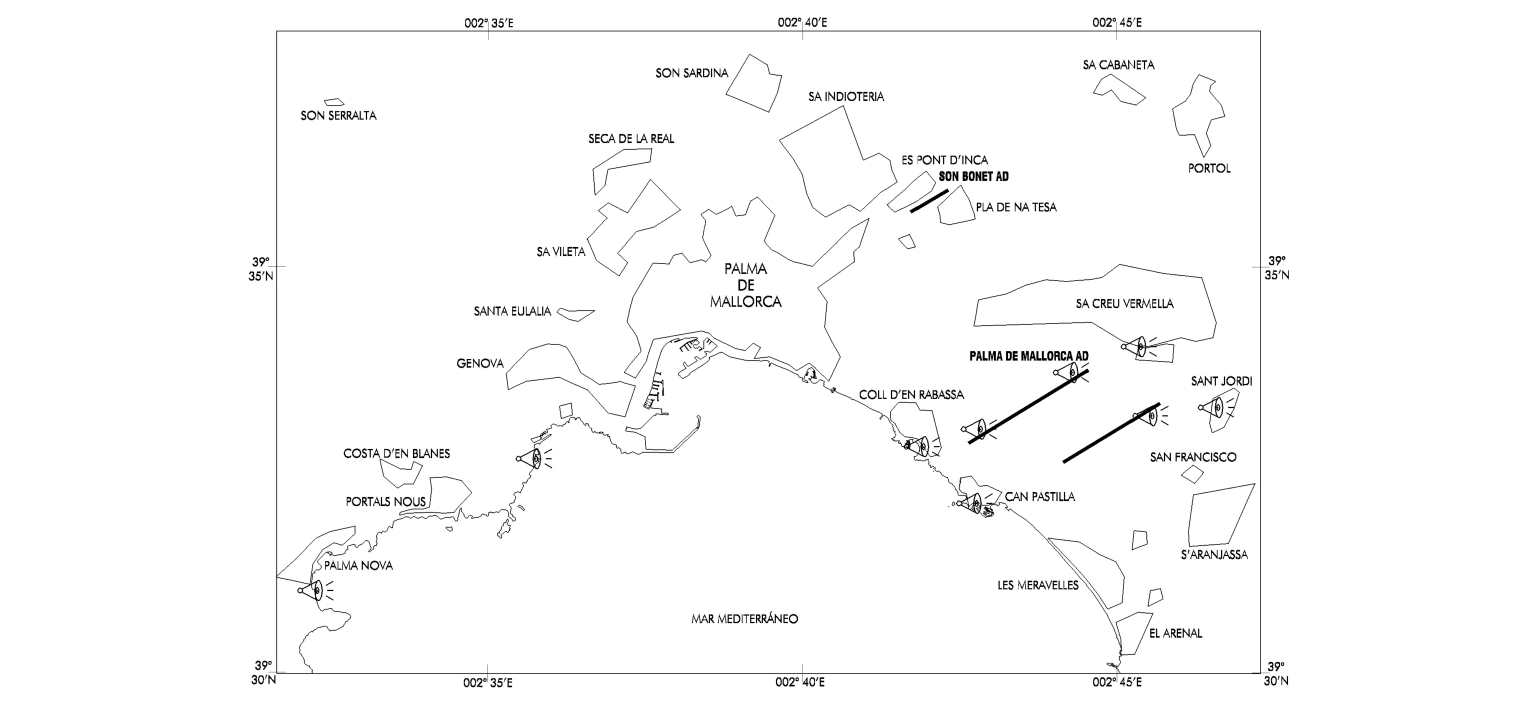
| LOCATION OF NOISE SENSORS | |
SAN JORDI |
393322N 0024639E |
CASA BLANCA |
393401N 0024523E |
THR RWY 24L |
393310N 0024534E |
THR RWY 24R |
393342N 0024418E |
THR RWY 06L |
393300N 0024250E |
CAN PASTILLA |
393205N 0024246E |
COLL DEN RABASSA |
393247N 0024156E |
ILLETAS |
393238N 0023546E |
PALMANOVA |
393100N 0023216E |
RUN-UP TEST
Run-up test of engines will be only authorized out of night hours and may be accomplished at TWY SOUTH. Any other situation must be authorized by the Aiport Management.
Engine performance testing higher than idle regime are forbidden in the stand. It just may be realized at TWY SOUTH.
Run-up tests at idle regime don't have schedule restriction. It can be made when the aircraft is in the stand, if the boarding bridge is disconnected and has been authorized by CEOPS.
Auxiliary Power Point (APU) tests may be authorized by CEOPS out of night hours if is not perceived an excessive noise in apron.
NOISE ABATEMENT PROCEDURES
-
TAKE-OFF
-
Take-off power. Take-off FLAP/SLAT.
-
Accelerate till V2 + 10 kt.
-
Climb up to 1500 ft AAL maintaining V2 + 10 kt.
-
-
At 1500 ft
-
Reduce to power of ascent.
-
Accelerate till VZF + 10 kt maintaining a minimum climb gradient of 500 ft/min. VZF: Zero flap minimum safety maneouvre speed.
-
Retract FLAP/SLAT, according to need.
-
- UP TO FL060
- Not exceed 250 kt and continue SID in force, except ATC clearance.
NOTE: Exceptions will be made for aircraft able to demonstrate that they generate less acoustic impact by using other procedures, which must be reported to the Airport Management sufficiently in advance, or for justified security reasons.
-
- LANDING
- REVERSE THRUST
- Reverse thrust other than idle thrust cannot be used, except for safety reasons, during night hours.
- Landing and approach procedures on visual meteorological conditions will be performed with an angle equal to or higher than the ILS GP or PAPI of each runway.
- REVERSE THRUST
TRAINING FLIGHTS
Repeated approaches for training purposes are only permitted prior authorization from the airport authority and will be restricted according to air traffic, complying with the local procedures.
FLIGHT PROCEDURES
ARRIVAL PROCEDURES
CLEARANCE LIMIT
Arriving aircraft proceeding on a Standard Arrival (STAR) will considered the IAF as clearance limit. With no further ATC clearance, enter the IAF holding.
APPROACH RADAR CONTROL
When arriving traffic is being sequenced by means of ATS Surveillance Systems, part of the approach will be flown under directions from Radar Control. Under radar control, the intermediate approach procedure may be partially or completely omitted, the clearance limit assigned may be replaced by a clearance to a final approach aid or fix, or radar vectors may be given to direct the aircraft to the final approach course or to a position from which a visual approach may be completed.
In case of dense traffic, radar vectoring from the IAF to a downwind leg position for the active runway should be expected.
Once the aircraft is under Radar Control, changes of heading or flight level/altitude will be made under instructions from the Radar Control, except in case of radio communication failure.
SPEED CONTROL
Speed Control is essential for safe and smooth operations, especially in dense traffic and during final approach.
Spacing provided between aircraft is minded to achieve maximum runway utilization within the parameters of safe separation minima (including vortex effect). See Use of Runways in item 20.
These speeds are mandatory for separation purposes and standardized approach procedures at Palma Airport.
Except otherwise instructed by ATC, pilots shall comply with the following speed restrictions:
-
MAX IAS 250 kt at FL100 or at the Speed Limit Point (SLP), whatever occurs first.
-
IAS 200 kt at 12.0 DME ILS.
-
IAS 180 kt at 9.0 DME ILS.
-
IAS 160 kt at 4.0 DME ILS;
or equivalent distance from threshold in case of DME ILS U/S.
All speed restrictions are to be flown as accurately as possible.
Aircraft unable to conform to these speeds due to weather conditions, aircraft performance or other operational reasons, should inform ATC immediately and state what speeds might be used.
In the event of a new (no-speed related) ATC clearance being issued, pilots are not absolved from a requirement to maintain a previously allocated speed.
Not compliance with speed control instructions may lead to an aircraft to be excluded from the planned approach sequence.
SHORT COMMUNICATION PROCEDURE
In transfers of communications from PALMA ARRIVAL to PALMA FINAL (FREQ 118.955 C), the initial call shall be limited to the flight CALL SIGN to avoid congestion on the frequency:
PALMA APPROACH + Aeroflot 321
UNINTENDED CROSSING OF FINAL APPROACH COURSE
In order to avoid unintended crossing of the final approach course when radio contact is not possible, if an aircraft is on a radar vector leading to the final approach course at an angle of 50 degrees or less, or if the aircraft has been cleared to a waypoint or aid located on the final approach course, the pilot shall turn inbound to the final approach of the previously assigned runway and shall adhere to the cleared altitude, unless the pilot has been instructed by ATC to cross the final approach course.
DELAY INFORMATION ON APPROACH
The expected approach time (EAT) will be provided to an arriving aircraft whose landing is expected to be delayed by 10 minutes or more, or any other period of time as determined by the competent authority.
VISUAL APPROACH
In the case of visual approach, aircraft shall maintain an altitude of:
-
1500 ft or above for code letter A and B aircraft.
-
1700 ft or above for code letter C and D aircraft.
and at least a height of 1000 ft AGL, until being in the final approach heading of the runway in use.
RADIO COMMUNICATION FAILURE PROCEDURE
An aircraft which experiences a communications failure shall immediately respond on the SSR mode 7600.
Procedures depending on the position of the aircraft at the time of the failure:
-
During a STAR procedure before the IAF:
Maintain last cleared flight level / altitude and hold over the IAF. Start descending after a complete holding pattern, or after the EAT if received, whatever is later, and complete a published IFR approach to the active runway for arrivals in order to land within the next 30 minutes.
-
On radar vectors before the IAF:
Maintain last cleared flight level / altitude, flight directly to the first suitable IAF and follow procedure stated on point a).
-
On radar vectors after the IAF:
Maintain last cleared flight level / altitude and proceed to the final approach course to complete the approach procedure and land. If unable, accomplish the missed approach procedure with communications failure stated in d).
-
During the missed approach:
Do not initiate the missed approach procedure before the MAPT, follow the procedure, join the holding, make a complete holding pattern, and complete the approach procedure and land.
DEPARTURE PROCEDURES
REFERENCE FIXES IN APPROACH COURSE
In order to facilitate and expedite the traffic of departing aircraft it is necessary to establish a number of reference fixes in the approach courses to the different runways. With these references and in IMC, an aircraft may be authorized to take off from a runway at the same time that approach operations are taking place in the same or another runway, as long as the course of the departing aircraft differs minus 45° from that of the incoming aircraft.
Reference fixes:
-
5.0 DME SSJ, aircraft on approach to RWY 24R.
-
5.0 DME ILS PLM, aircraft on approach to RWY 06L.
-
5.0 DME ILS IPAL, aircraft on approach to RWY 24L.
SPEED CONTROL
In order to optimize the departure flow and assist in the separation between successive departing aircraft, a speed limit of MAX IAS 250 kt at FL100 or below is applicable. ATC may remove the speed restriction by using the phrase ‘No ATC Speed Restriction’.
Pilots are reminded that this phrase does not relieve the pilot of the responsibility to adhere to the Noise Abatement Procedures that may require a speed/power limitation.
RADIO COMMUNICATION FAILURE PROCEDURES
An aircraft which experiences a communications failure shall immediately respond on the SSR mode 7600.
Procedures depending on the position of the aircraft at the time of the failure:
-
During a SID procedure:
Follow the SID to the TMA exit point, climbing to the last cleared altitude/flight level, or the minimum safety altitude, whatever is higher; maintain such level or altitude for 7 minutes, continue climbing in accordance with the updated FPL.
-
On radar vectors on departure:
Intercept, in the most direct way, the last SID procedure given by ATC and continue the failure communications procedure stated in a).
If SID clearance has not been received, proceed to intercept the appropriate SID to the TMA exit point in accordance with the FPL.
CONTINUOUS DESCENT OPERATIONS
Depending on traffic situation, and if no need for interrupting the descent is foreseen, aircraft will be cleared to proceed to a standard arrival (STAR), or by means of a “direct to” clearance to an intermediate fix of the STAR, to the IAF, to an intermediate approach fix or to the IF, to the minimum altitude of the IAF or the IF of the instrumental procedure (IAC), in order to allow a continuous descent operation
LOW VISIBILITY PROCEDURES (LVP)
GENERAL
RWY 24L, provided that the facilities required are in service, is appropriate for CAT II and III operations.
RWY 24R, 24L (prior clearance or cases of contingency due to be subject to environmental limitations), 06R and 06L are appropriate for take-offs in low visibility conditions.
During the performance of these operations, the Low Visibility Procedures (LVP) will be applied. If so, pilots will be informed via ATIS or via RTF. In any case, LVP are active in the manoeuvring area when RVR is equal to or lower than 550 m and in apron when RVR is lower than 400 m.
In the event of weather conditions leading to LVP activation but activation cannot be accomplished (e.g., due to rapid deterioration of weather conditions, infrastructure-related issues, etc.), all operations may be halted (landing, take-off and taxiing) until LVP may be activated.
In the event of weather conditions leading to the activation of LVP and only affecting one threshold while there are no low visibility conditions at the other threshold, the unaffected threshold may be used in CAT I, if circumstances permit it, maintaining LVP in force.
Guided low visibility take-offs (LVTO) are not permitted.
GROUND MOVEMENT
ATC will employ the lit intermediate holding position, as well as the stop bars as clearance limits to manage the ground movements.
With RVR values below 400 m and A-SMGCS (Advanced Surface Movement Guidance and Control Systems) inoperative, or with RVR values below 400 m and SMR operative (MLAT multilateration system out of service), aircraft will taxi guided by a "FOLLOW ME" vehicle from/to the stand (or position after towing) to/from the assigned apron exit/entry GATE. When the RVR is less than 75 m, no new clearances will be issued, and taxiing to the apron may only be completed with the guidance of signalmen.
Helicopters will be guided by a "FOLLOW ME" vehicle on the apron when LVP are in force.
When an aircraft follows a "FOLLOW ME" vehicle, the commander shall be responsible for maintaining their own separation from the vehicle.
When LVP are activated in the manoeuvring area, the following will be closed:
-
Perimeter service roads:
-
South perimeter from General Aviation to SEI South.
-
North perimeter from East Apron to TWY Link.
-
When LVP are activated in the manoeuvring area and apron, the service roads bounded by the following stands will be closed:
-
PRKG 06-103.
-
PRKG 103-104 and passing through GATE D.
-
PRKG 109-114 and passing through GATE E.
-
PRKG 118-119 and passing through GATE F.
-
PRKG 123-48.
In addition, possible closure, depending on whether or not there are aircraft parked, from the estimated off-block time and for the estimated duration of the LVP, of the following vehicle service roads (whenever any of these service roads does remain open, its use will be controlled by a "FOLLOW ME" vehicle).
-
Service road linking PRKG 02 with 100.
-
Service road linking PRKG 22 with 109.
-
Service road linking PRKG 25/26 with 116.
-
Service road linking PRKG 28/29 with 121-123.
ARRIVALS
-
Clearance to land will be issued when the ILS sensitive areas are free, normally, before the approaching aircraft is at 2 NM from the touchdown point. Nevertheless, concession of clearance to land may be delayed until the aircraft is at 1 NM from the touchdown point, always provided that the CTA monitors the development of the approach and the pilot has been advised that they will be supplied with landing clearance late.
-
Aircraft that have landed should vacate the runway in use by any of the taxiways specified below, except when they receive different clearance from ATC:
RWY |
TWY |
|---|---|
06L |
N2, N3 |
24R |
N4 |
24L (1) |
S1, S2 |
(1) In cases where aircraft vacate RWY 24L at the end, they shall always do so via TWY H7 if possible. |
|
-
On vacating the runway, the pilots shall notify:
-
The taxiway used, and
-
Runway vacated (CAT I), or
-
Sensitive area vacated (CAT II/III). The limit of the sensitive area is determined by the transition of the taxiway centre line lights from green-yellow-green to all green.
-
-
Aircraft leaving the sensitive area will have priority over those that may be taxiing nearby.
-
After vacating the runway, aircraft shall taxi following the taxiway centreline lights until they vacate the LSA, where they will receive instructions from GMC, or else they shall halt.
DEPARTURES
-
Pilots shall request ATC to engines start-up when the meteorological minimum values are equal to or higher than its operation minima.
-
The clearance of push-back, towing and/or taxiing will be requested to GMC (see AIP-España, AD 2-LEPA/LESJ item 18).
-
The following runway-holding positions will be used, except when they receive different clearance from ATC.
TAKE-OFF RUNWAY |
HOLDING POSITION (1) |
|---|---|
06R |
H8 (CAT II/III) |
06L |
H4, H5 |
24R |
H1, H2 |
24L (2) |
H9, H10 |
(1) See operational restrictions on runway-holding positions published in AIP. (2) Use of RWY 24L for take-offs is subject to environmental limitations and it may only be used with prior clearance from the airport or in cases of contingency. |
|
-
Take-offs from intersection are not permitted when LVP are activated.
-
In the event of abandoning the take-off manoeuvre, ATC shall be notified immediately, who will give appropriate instructions. With the LVP in force, if a take-off manoeuvre is aborted, the aircraft shall vacate the runway via the end.
RUNWAY IN USE FOR TAKE-OFF |
EXIT TAXIWAY TO BE USED IN THE EVENT OF ABANDONED TAKE-OFF |
|---|---|
06L |
H2 / H1 |
24R |
H4 / H5 |
06R |
H9 / H10 |
24L |
S1 / S2 / S3 / H8 / H7 / H6 |
TAXIING
Once activated the LVP, preferentially, operations will be carried out on West configuration.
The taxiing routes described in AIP-España AD 2-LEPA/LESJ item 20 shall be followed.
COMMUNICATIONS FAILURE AND ANOMALOUS SITUATIONS IN THE MANOEUVRING AREA
Communications failure
If an aircraft or vehicle operating in the manoeuvring area or an aircraft or "FOLLOW ME" vehicle on the apron should suffer a communications failure, it shall proceed as follows:
-
Departing Aircraft
The aircraft shall continue by the assigned route and halt at the limit of the ATC clearance, taking extreme care, where it shall hold and await the arrival of a "FOLLOW ME" vehicle which will guide it to the assigned stand or holding bay.
-
Arriving Aircraft
If the aircraft has just landed, it shall hold its position on vacating the runway (or the sensitive area) and await the arrival of a "FOLLOW ME" vehicle, which will guide it to the assigned stand.
If the aircraft already has ATC taxiing clearance, it shall continue by the assigned route and halt at the limit of the ATC clearance, taking extreme care, where it shall hold and await the arrival of a "FOLLOW ME" vehicle which will guide it to the assigned stand.
-
Vehicle
In the case of failure of radiotelephone communications with the Aerodrome Control Services when the driver is within the Manoeuvring area, the general procedure for action will be:
-
Normally, the driver will exit the manoeuvring area before halting and awaiting help.
-
If the driver has a transmitter for the CEOPS frequency, this situation must be reported to that unit, and assistance required.
-
Abnormal situations in the manoeuvring area
Uncertainty about position in the manoeuvring area
-
Other than as provided for in the following paragraph, if a pilot is in doubt about the position of the aircraft in relation to the manoeuvring area, they must immediately halt the aircraft and report this circumstance to ATC (including the last known position).
-
In situations in which a pilot is in doubt about the position of the aircraft in relation to the manoeuvring area, but recognises that the aircraft is on a runway, the pilot shall immediately report this to ATC (including the last known position), and vacate the runway as soon as possible, if they can find an appropriate taxiway nearby, unless ATC should indicate otherwise, and then, halt the aircraft.
-
In the event of disorientation of a vehicle in the manoeuvring area, this fact shall be communicated to ATC (including the last known position) and, unless other indications are received from ATC, the driver shall exit the manoeuvring area to reach a safe distance as soon as possible, and halt the vehicle.
-
In the event that ATC realises that an aircraft or vehicle has lost its position in the manoeuvring area, or is not sure of its position, the appropriate measures will be taken immediately to safeguard the operations and help the aircraft or vehicle in question to determine its position.
Loss of visual contact between traffic
-
In the event that one aircraft loses visual contact with another, or with a vehicle with which it is maintaining its own separation, ATC shall be informed immediately, and the aircraft halted. ATC will take the measures that it will deem fit (for instance, sending an assistance vehicle).
Breakdown of aircraft or vehicle
-
Aircraft: shall report the situation to ATC and await the arrival of assistance. Should it find itself on a runway, if possible and unless ATC should indicate otherwise, this shall be vacated.
-
Vehicle: shall communicate this fact to ATC (including the last known position) and, unless other indications are received from ATC and this is possible, the driver shall exit the manoeuvring area to reach a safe distance as soon as possible, and halt the vehicle. If the vehicle cannot be moved, ATC shall be informed without delay.
ATS SURVEILLANCE SYSTEM
It is used in the provision of the aerodrome control service to perform the following functions:
-
supervision of the flight path of aircraft on final approach;
-
supervision of the flight path to other aircraft in the vicinity of the aerodrome;
-
establishment of separation, as defined in the R.C.A. section 4.6.7.3, between successive departing aircraft; and
-
provision of navigation assistance to VFR flights.
All the functions above will be suspended in the event of simultaneous unavailability of Palma de Mallorca and Randa radars.
VFR TRAFFIC
Tower may authorize, according to the “Reglamento de Circulación Aérea”, local, test or instruction flights with VFR flight plan subject to the authorization of the aerodrome authority.
Tower may clear aircraft with two way radio and VFR flight plan, to depart or enter the TMA and CTR via the appropriate VFR corridors or sectors specially furnished for that purpose. See AD 2-LEPA/LESJ VAC and ENR 6.10.
VISUAL DEPARTURE PROCEDURES FOR IFR FLIGHTS
In certain circumstances in which the published SID and contingency departures cannot be used, IFR flights may request a "visual departure” from ATC under the following conditions:
-
Between the start of morning civil twilight and the end of evening civil twilight.
-
Weather conditions in the direction of the take-off and subsequent initial climb that permit the visual flight up to the Minimum Radar Altitude.
-
Once lined up, the pilot will propose a heading to ATC, to enable the departure to be safe.
-
The pilot will be responsible for maintaining obstacle clearance up to the Minimum Radar Altitude.
Noise abatement procedures described in AD 2-LEPA/LESJ ITEM 21.- NOISE ABATEMENT PROCEDURES which are incompatible with these visual departures will not apply.
AD TRAFFIC CIRCUIT
RWY 06L/06R
AD traffic circuit to the right (South) / left (North).
RWY 24R/24L
AD traffic circuit to the left (South) / right (North).
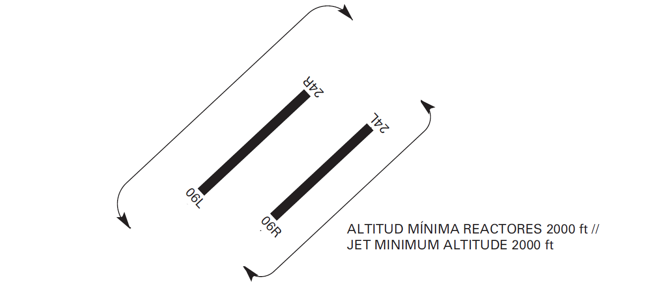
ADDITIONAL INFORMATION
ARRESTING SYSTEMS
Nomenclature: LESJ-01-C-B.
Type: RETRACTABLE CABLE BARRIER BIDIRECTIONAL.
Location on: RWY 06R THR displaced + 650 m/+2133 ft.
RWY 24L THR +1940 m/+6365 ft.
Readiness status: Permanently available, at the pilot request.
AIRCRAFT EQUIPPED WITH TCAS, VERSION PRIOR TO Nº 7, OPERATING AT PALMA DE MALLORCA AD
For permanent radar performance checking of the new en-route radar installed at Randa, a fixed radar transponder has been located at the TWR with the following characteristics:
-
Location: 393255.11N 0024359.13E
-
Alpha Mode Code: 7777
-
Antenna altitude: 100 ft
Aircraft equipped with TCAS, version prior to Nº 7, overflying at low altitude next to these coordinates, may receive TCAS traffic advisories corresponding to this fixed transponder. Such identifications do not identify real traffic and should be ignored.
ON-BOARD MEDICAL ATTENTION
In the event that a passenger requires on-board medical attention, the pilot-in-command will notify ATC whether:
-
He/she requires a doctor on board, or
-
He/she does not require a doctor on board.
In the case of requiring a doctor on board:
-
The passengers will remain seated until the medical service takes care of the patient.
-
Medical personnel will travel to the aircraft.
In the case of not requiring a doctor on board:
-
The PMR vehicle will travel to the aircraft to transport the patient to the airport First Aid Room for assessment by medical staff.
BIRDS CONCENTRATION AREAS
Fauna Control Service schedule: Sunrise to Sunset.
Presence of fauna due to different points of attraction for fauna within and in the vicinity of the airport, as described below:
Movement A. Displacements of yellow-legged gulls crossing the two runways (at 30 to 300 ft AGL) individually or in groups of up to 10.
Movement C. Possible transit in winter by compact flocks of common starlings crossing both runways at sunrise and one hour before sunset (at 30 to 600 ft AGL).
Movement E. Displacements of cattle egrets crossing the two runways (at 30 to 300 ft AGL).
Zone B. Spring concentration of common swifts.
Zone D. Forest cover con presence of wood pigeons (all year) and common starling (winter).
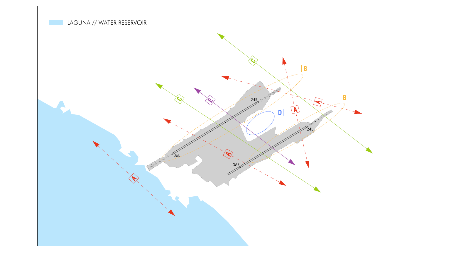
FOAM COVERING OF RUNWAYS
In case of emergency landing, foam covering service of runways as a safety measure is not provided.
SHIELDING OF APPROACH LIGHTS
SHIELDED ELEMENT |
RWY |
SHIELDING OBJECT |
CONSEQUENCE |
|---|---|---|---|
Crossbar located at 450 m from threshold |
06L |
Road |
The visual reference provided by the crossbar located at 450 m from threshold disappears. |
2 central lights located at 480 m from threshold |
06L |
Road |
The distance between the lights in the central line will be 81 m. |
AERONAUTICAL CHARTS RELATED TO AN AERODROMECHARTS RELATED TO THE AERODROME
The list of charts related to the aerodrome can be found on the link below:
VISUAL SEGMENT SURFACE (VSS) PENETRATION
The instrument approach procedures affected, can be found below:
IAC 1 RNP Z RWY 06L: LPV.
IAC 2 RNP Y RWY 06L: LNAV, LNAV/VNAV.
IAC 3 ILS Z RWY 06L: direct approach.
IAC 4 ILS Y RWY 06L: direct approach.
IAC 5 VOR RWY 06L: direct approach.
IAC 8 VOR RWY 06R: direct approach.
IAC 9 RNP Z RWY 24L: LPV.
IAC 10 RNP Y RWY 24L: LNAV, LNAV/VNAV.
IAC 11 ILS Z RWY 24L: direct approach.
IAC 12 ILS Y RWY 24L: adirect approach.
IAC 13 LOC RWY 24L: direct approach.
IAC 14 RNP Z RWY 24R: LPV.
IAC 15 RNP Y RWY 24R: LNAV, LNAV/VNAV.
IAC 16 ILS Z RWY 24R: direct approach.
IAC 17 ILS Y RWY 24R: direct approach.
IAC 18 ILS X RWY 24R: direct approach.
IAC 19 VOR RWY 24R: direct approach.