LEVC AD 2 AERODROME DATA
AERODROME LOCATION INDICATORAND NAME
LEVC - VALENCIA
AERODROME GEOGRAPHICAL AND ADMINISTRATIVE DATA
ARP |
392922N 0002854W. See AD 2-LEVC ADC. |
|
Distance and direction from the city |
8 km W. |
|
Elevation |
73 m / 240 ft. |
|
Geoid undulation |
50.23 m ± 0.05 m (1). |
|
Reference temperature |
31°C. |
|
Low average temperature |
9ºC. |
|
Magnetic variation |
1º E (2020). |
|
Annual change |
7.5' E. |
|
AD administration |
Aena. |
|
Address |
Aeropuerto de Valencia; 46940 Manises; Valencia. |
|
TEL |
+34-961 598 500 |
|
|
FAX |
+34-961 598 510 |
AFTN |
LEVC |
|
Approved traffic |
IFR/VFR. (2) (3) |
|
Remarks |
(1) For all AD points. (2) For air traffic security reasons:
Except: hospital, SAR, emergencies and state flights. Business and General Aviation Traffic (IFR/VFR) may be conditioned on the declared capacity. IFR school and training flights permitted only from 0100 LT to 0500 LT. Occasionally, restrictions may apply, which will be published by NOTAM. Local Scheduling Coordination Office:
Flights without clearance are not allowed. (3) See Local Regulations. |
OPERATIONAL HOURS
Airport |
H24. |
|
Customs and Immigration |
HR AD. |
|
Health and Sanitation |
See GEN 1.4. |
|
AIS/ARO |
H24. (1) |
|
MET briefing |
HR AD. |
|
ATS |
HR AD. |
|
Fuelling |
HR AD. |
|
Handling |
HR AD. |
|
Security |
HR AD. |
|
De-icing |
No. |
|
Remarks |
(1) Centralised ARO Office geographical area 8
Centralised AIO Office - International NOTAM Office
|
HANDLING SERVICES AND FACILITIES
Cargo facilities |
Up to 3000 kg. |
|
Fuel types |
GNA AVGAS 100LL, RD 2494 JET A-1. (1) |
|
Oil types |
AEROSHELL W-100, 15W50. |
|
Refuelling |
AVGAS 100 LL: 1 truck 5500 L; 3 L/s. JET A-1: 3 trucks 40000 L, 2 trucks 30000 L, 2 trucks 20000 L, 1 truck 10000 L; 100 L/s |
|
De-Icing facilities |
No. |
|
Hangar space |
No. |
|
Repair facilities |
Cessna aircraft maintenance hangar. |
|
Remarks |
A handling agent must be used for all operations, including non-commercial operations. Except: hospital, SAR, emergencies and state flights. For arrival operations, passengers and crew must wait for their handling agent. Commercial and Cargo aviation handling agents:
General Aviation handling agents:
(1) Fuelling requests:
|
PASSENGER FACILITIES
Hotels |
No. |
|
Restaurant |
Yes. |
|
Transportation |
Buses, taxis, car hire and underground. |
|
Medical facilities |
First aid. (1) |
|
Bank/Post Office |
No. |
|
Tourist information |
Yes. |
|
Remarks |
(1) See item 3 for hours of operation. |
RESCUE AND FIREFIGHTING SERVICES
Fire category |
7. (1) (2) |
|
Rescue equipment |
In accordance with the fire category published. |
|
Removal of disabled aircraft |
Crane trucks not belonging to AD, with a maximum lifting capacity of 500 TM. 10 m OLCOVEN recovery straps used to lift aircraft, maximum weight 8000 kg single and straight, 16000 kg double and straight. 3 mini high power lifting bags, for transporting aircraft with damaged landing gear, up to 60 cm inflated. |
|
Remarks |
(1) The response time of the rescue and fire fighting service is less than 3 MIN, with an operational objective of less than 2 MIN. (2) 8 and 9 exceptionally (see item 20, "Procedure for requesting of exceptional fire category"). |
RUNWAY SURFACE CONDITION ASSESSMENT AND REPORTING, AND SNOW PLAN
Types of clearing equipment |
Not applicable. |
|
Clearance priorities |
Not applicable. |
|
Use of material for movement area surface treatment |
Not applicable. |
|
Specially prepared winter runways |
Not applicable. |
|
Remarks |
Runway surface condition assessment and reporting in accordance with the Global Reporting Format (GRF) methodology described in AD 1.2.2. Aerodrome in service during all seasons of the year. |
APRONS, TAXIWAYS AND CHECK LOCATIONS/POSITIONS DATA
Apron |
Surface: North: Concrete. South: Concrete. R4: Asphalt pavement. Strength: North: PCN 143/R/A/W/T, EXC: PRKG 1 to 6B & 7 to 12: PCN 84/R/B/W/T; PRKG 52 to 60: PCN 150/R/B/W/T; GATE-A: PCN 58/F/A/W/T; GATE-B, GATE-C: PCN 134/F/A/W/T; GATE-D: PCN 101/F/A/W/T; PRKG BT5 & TWY W1: PCN 39/R/C/W/T. South: PCN 26/R/C/W/T, EXC: TWY W13 up to GATE-F: PCN 84/F/A/W/T; TWY W14, PRKG 101 to 108, PRKG 201 to 206 & PRKG 211 to 216: PCN 76/R/A/W/T. R4: PCN 30/F/D/W/T. |
|
Taxiways |
Width: 23 m. EXC T2 and H5: 45 m. Surface: Asphalt. Strength: TWY N3, N4, H7, H8, H9: PCN 134/F/A/W/T. TWY H1, N1, H3, H4, N2, H6: PCN 84/F/A/W/T. TWY H2: PCN 65/F/B/W/T. TWY S1 to S4, T1, T3, T4: PCN 40/F/A/W/T. TWY H5, T2: PCN 84/F/A/W/T. TWY M1, M2: PCN 101/F/A/W/T. TWY W2: 84/R/B/W/T. TWY W3, W4, W5: PCN 143/R/A/W/T. TWY W6: PCN 150/R/B/W/T. TWY W11 BTN PRKG 201 to 203: PCN 84/F/A/W/T. TWY W11 BTN PRKG 203 to 206: PCN 76/R/A/W/T. TWY W11 BTN PRKG 206 to 208: PCN 26/R/A/W/T. TWY W13 BTN GATE F & PRKG 108: PCN 84/F/A/W/T. TWY W15, W-16: PCN 26/R/C/W/T. TWY Y1, Y2 BTN PRKG 207 to 208 & 209 to 210: PCN 26/R/C/W/T. TWY Y1, Y2 BTN PRKG 201 to 206 & 211 to 216: PCN 76/R/A/W/T. |
|
Check locations |
Altimeter: Apron:
VOR: No. INS: No. |
|
Remarks |
None. |
SURFACE MOVEMENT GUIDANCE AND CONTROL SYSTEM AND MARKINGS
Taxiing guidance system |
Runway holding positions, lighted boards, stop bars, intermediate holding positions, NO ENTRY boards, PRKG and runway guard lights. |
|
RWY markings |
Centre line, threshold, displaced threshold RWY 30, designators, distance to go information, side stripe, touchdown zone and aiming point. |
|
TWY markings |
Centre line and side stripe. |
|
Remarks |
None. |
AERODROME OBSTACLES
Obstacles which penetrate Approach, Take-Off Climb, Conical, Inner Horizontal, Transitional, Inner Transitional and Balked Landing Surfaces established in ICAO Annex 14; and the areas 2A and 3 established in ICAO Annex 15. Those penetrating these surfaces are identified in the CSV file as "Relevante_Relevant = Si/Yes". |
See Item 10 and Data Set. |
|
Remarks |
See AD 2-LEVC AOC. |
METEOROLOGICAL INFORMATION PROVIDED
MET office |
Valencia MET. |
|
HR |
H24. |
|
METAR |
Half-hourly. |
|
TAF |
24 HR. |
|
TREND |
Yes. |
|
Briefing |
In person and by telephone. |
|
Flight documentation/Language |
Charts and plain language / Spanish. |
|
Charts |
Forecasted significant and wind and temperature in altitude maps. |
|
Supplementary equipment |
Clouds and lightning image and radar information display. |
|
ATS unit served |
TWR, APP. |
|
Additional information |
Valencia OMAe (LEVA): H24
MET office Valencia: H24
|
|
Remarks |
Aerodrome climatological summary available. Aerodrome warnings available. |
RUNWAY PHYSICAL CHARACTERISTICS
RWY |
Direction |
DIM (m) |
THR PSN |
THR ELEV TDZ ELEV |
SWY (m) |
CWY (m) |
Strip (m) |
OFZ |
RESA (m) |
RWY/SWY SFC PCN |
|---|---|---|---|---|---|---|---|---|---|---|
12 (2) |
116.16°GEO 116°MAG |
3215 x 45 |
392946.8700N 0003000.4100W |
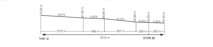
THR: 73.0 m/240 ft TDZ: 73.0 m/240 ft |
No |
No |
3335 x 280 |
Yes |
240 x 150 |
RWY: ASPH PCN 119/F/A/W/T PCN 84/F/A/W/T (3) PCN 134/F/A/W/T (4) SWY: No |
30 (1) |
296.18°GEO 296°MAG |
3215 x 45 |
392905.1900N 0002810.9600W |
THR: 53.3 m/175 ft TDZ: 59.3 m/195 ft |
No |
No |
3335 x 280 |
Yes |
240 x 150 |
RWY: ASPH PCN 119/F/A/W/T PCN 84/F/A/W/T (3) PCN 134/F/A/W/T (4) SWY: No |
Remarks: (1) THR 30 displaced 300 m. (2) End RWY 12 coordinates: 392900.90N 0002759.70W (3) Touchdown zone RWY 12 (4) Touchdown zone RWY 30 |
||||||||||
Profile
DECLARED DISTANCES
RWY |
TORA (m) |
TODA (m) |
ASDA (m) |
LDA (m) |
|---|---|---|---|---|
12 |
3215 |
3215 |
3215 |
3215 |
30 |
3215 |
3215 |
3215 |
2915 |
12 INT T4 |
2723 |
2723 |
2723 |
-- |
12 INT T3 |
2391 |
2391 |
2391 |
-- |
12 INT H6 |
1787 |
1787 |
1787 |
-- |
12 INT T2 |
1475 |
1475 |
1475 |
-- |
30 INT H2 |
3052 |
3052 |
3052 |
-- |
30 INT H3 |
2564 |
2564 |
2564 |
-- |
30 INT T2 |
1787 |
1787 |
1787 |
-- |
Remarks: None. |
||||
APPROACH AND RUNWAY LIGHTING
Runway |
12 |
|
Approach |
Precision CAT I 900 m. LIH. |
|
PAPI (MEHT) |
3° (16.50 m / 54 ft). (1) |
|
Threshold |
Green. |
|
Touchdown zone |
No. |
|
Runway centre line |
3215 m: 2315 m white + 600 m white and red + 300 m red. LIH. Distance between lights: 30 m. |
|
Runway edge |
3215 m: 2615 m white + 600 m yellow. LIH. Distance between lights: 50 m. |
|
Runway end |
Red. |
|
Stopway |
No. |
|
Remarks |
(1) PAPI not usable for aircraft code letter E or F aircraft, or aircraft MD11, A30B or B764. |
Runway |
30 |
|
Approach |
Precision CAT I 900 m. LIH. |
|
PAPI (MEHT) |
3° (17.48 m / 57 ft). (1) |
|
Threshold |
Green. |
|
Touchdown zone |
No. |
|
Runway centre line |
3215 m: 2315 m white + 600 m white and red + 300 m red. LIH. Distance between lights: 30 m. |
|
Runway edge |
3215 m: 300 m red + 2315 m white + 600 m yellow. LIH. Distance between lights: 50 m. |
|
Runway end |
Red. |
|
Stopway |
No. |
|
Remarks |
(1) PAPI not usable for aircraft code letter E or F aircraft, or aircraft MD11, A30B or B764. |
OTHER LIGHTING, SECONDARY POWER SUPPLY
ABN/IBN |
No. |
|
WDI |
1 near THR 12, 1 near THR 30. LGTD. |
|
TWY lighting |
Edge in T3, T4, S1, S2, S3, S4 and M2. Centre line in N1, N2, N3, N4, H1, H2, H3, H4, H5, H6, H7, H8, H9, M1, T1 and T2. |
|
Apron lighting |
23 floodlight towers on north apron, 7 floodlight towers on south apron and 8 floodlight towers on cargo apron. Apron edge lights on north apron and R4 and retroreflective apron edge markers on the rest of aprons. |
|
Secondary power supply |
Uninterrupted power supply (UPS) for all aeronautical lighting systems. Included obstacles lights. |
|
Remarks |
The following visual aid circuits have LED lights:
|
HELICOPTER LANDING AREA
Position |
FATO: RWY 12/30. Coordinates THR 12 and THR 30, see item 12. Ground taxiing: TLOF same as RWY 12/30. Coordinates 392922N 0002854W (same as ARP). Air taxiing: TLOF same as PRKG 125, 126, 127, 128, 129, 130, 131, 132, 133, 134, 135, 148, 149, 152 and 153. |
|
Elevation |
FATO: RWY 12/30. THR 12 and THR 30 elevation, see item 12. Ground taxiing: TLOF same as RWY 12/30. Elevation 60.80 m (same as ARP). Air taxiing: TLOF same as PRKG 125, 126, 127, 128, 129, 130, 131, 132, 133, 134, 135, 148, 149, 152 and 153. (*) See table below. |
|
Dimensions, surface, maximum weight, marking |
FATO: RWY 12/30. Ground taxiing: TLOF same as RWY 12/30, see item 12. Air taxiing: TLOF same as PRKG 125, 126, 127, 128, 129, 130, 131, 132, 133, 134, 135, 148, 149, 152 and 153: Hydraulic concrete PCN 70/R/A/W/T. Circular strip 50 cm wide, with an inner diameter of 8.63 m at PRKG 148, 149 and 153; 10.0 m at PRKG 152. PRKG 125 to 135 for helicopter parking for taxiing without turning. |
|
Direction |
No. |
|
Declared distances |
No. |
|
Lighting |
No. |
|
Remarks |
Air Taxiing: Maximum dimensions of helicopters. See AD 2-LEVC PDC 2. |
(*)
PRKG |
ELEV (M) |
125 |
58.22 |
126 |
58.30 |
127 |
58.38 |
128 |
58.45 |
129 |
58.54 |
130 |
58.60 |
131 |
58.66 |
132 |
58.75 |
133 |
58.86 |
134 |
58.91 |
135 |
59.05 |
148 |
59.06 |
149 |
58.92 |
152 |
58.42 |
153 |
58.26 |
AIR TRAFFIC SERVICES AIRSPACE
Designation |
CTR VALENCIA. |
|
Lateral limits |
394033.0N 0004701.0W; 393806.0N 0004142.0W; 393729.4N 0003643.3W; 393105.3N 0002312.9W; 392750.9N 0001444.7W; 392201.4N 0001827.2W; 392856.1N 0003855.5W; 393044.5N 0004418.9W; 393053.6N 0004446.2W; 393343.2N 0005216.1W; 394033.0N 0004701.0W. |
|
Vertical limits |
SFC - 6000 ft AMSL. |
|
Airspace class |
D. |
|
Unit Language |
VALENCIA APP. ES/EN. |
|
Transition altitude |
1850 m / 6000 ft. |
|
Hours of applicability |
-H24. |
|
Remarks |
- |
Designation |
ATZ VALENCIA. |
|
Lateral limits |
393401.1N 0002923.1W; 393120.0N 0002343.8W; 392508.6N 0002739.8W; 392711.1N 0003343.1W; 393401.1N 0002923.1W. |
|
Vertical limits |
SFC - 2500 ft AMSL. |
|
Airspace class |
D. |
|
Unit Language |
VALENCIA TWR. (1) ES/EN. |
|
Transition altitude |
- |
|
Hours of applicability |
-HR AD. |
|
Remarks |
(1) Call sign: Valencia TWR. HR ATS: see item 3. |
AIR TRAFFIC SERVICES COMMUNICATION FACILITIES
Service |
Call sign |
FREQ |
HR |
Remarks |
|---|---|---|---|---|
APP |
Valencia APP |
119.075 MHz |
H24 |
BACK-UP |
120.100 MHz |
H24 |
APP/L |
||
124.750 MHz |
H24 |
APP/H |
||
363.550 MHz |
H24 |
APP/MIL |
||
TWR |
Valencia TWR |
118.555 C |
H24 |
- |
125.480 C |
H24 |
BACK-UP |
||
121.500 MHz |
H24 |
EMERG |
||
121.880 C |
H24 |
GMC |
||
123.580 C |
H24 |
CLR |
||
243.000 MHz |
H24 |
EMERG |
||
257.800 MHz |
H24 |
- |
||
ATIS |
Valencia Información |
121.080 C |
H24 |
- |
D-ATIS |
Valencia Información |
NIL |
H24 |
Provision of ATIS information via data link. |
RADIO NAVIGATION AND LANDING AIDS
Facility (VAR) |
ID |
FREQ |
HR |
Coordinates |
DME ELEV |
Remarks |
|---|---|---|---|---|---|---|
DVOR (1º E) |
VLC |
116.100 MHz |
H24 |
392908.3N 0002859.0W |
- |
COV 40 NM AVBL BTN:
R-209 AVBL: FL080 at 60 NM, FL100 at 90 NM, FL140 at 100 NM overlap with VOR AMR. R-233 U/S FM 50 NM. |
DME |
VLC |
CH 108X |
H24 |
392908.0N 0002859.5W |
60 m |
COV 40 NM AVBL BTN:
R-209 AVBL: FL080 at 60 NM, FL100 at 90 NM, FL140 at 100 NM overlap with DME AMR. R-233 U/S FM 50 NM. |
DVOR (0º) |
CLS |
117.550 MHz |
H24 |
394225.8N 0005910.8W |
- |
COV 40 NM U/S BTN:
R-348 COV 6000 ft AMSL 38 NM. R-143 COV FL070 22 NM. R-154 COV FL070 29 NM, FL130 67 NM. R-173 COV FL070 26 NM, FL130 65 NM. |
DME |
CLS |
CH 122Y |
H24 |
394225.9N 0005911.4W |
570 m |
COV 40 NM U/S BTN:
R-348 COV 6000 ft AMSL 38 NM. R-299 COV FL085 30 NM. R-154 COV FL070 21 NM. R-173 COV FL070 29 NM. R-143 COV FL070 22 NM. |
NDB (1º E) |
SGO |
356.000 kHz |
H24 |
394027.1N 0001228.1W |
- |
COV 50 NM. |
LOC 12 (1º E) ILS CAT I |
VLN |
111.500 MHz |
H24 |
392855.3N 0002745.0W |
- |
116º MAG / 692 m FM THR 30 COV 25 NM |
GP 12 |
- |
332.900 MHz |
392938.1N 0002948.7W |
- |
3º; RDH 16 m at 372 m FM THR 12 & 120 m FM RCL on the right in the APCH direction. COV 10 NM AVBL BTN ±8 FM RCL at 2400 ft or ABV. Full fly-up indications may not be received BLW GP. |
|
ILS/DME 12 |
VLN |
CH 52X |
H24 |
392938.1N 0002948.7W |
75 m |
REF DME THR 12 |
LOC 30 (1º E) ILS CAT I |
IVC |
110.100 MHz |
H24 |
392954.5N 0003020.4W |
- |
296° MAG / 534 m FM THR 12. COV 25 NM |
GP 30 |
- |
334.400 MHz |
H24 |
392905.5N 0002823.4W |
- |
3°; RDH 16.30 m; at 271 m FM THR 30 & 123 m FM RCL on the left in the APCH direction. |
ILS/DME 30 |
IVC |
CH 38X |
H24 |
392905.5N 0002823.4W |
57 m |
REF DME THR 30. |
LOCAL AERODROME REGULATIONS
AD closed to aircraft without two-way radiocommunications.
In the event of failure in the centre line and/or edge lights of a TWY in use, with subsequent loss of guidance, pilots will stop taxiing, notify ATC of the incidence and wait for the arrival of a "FOLLOW ME" vehicle, which will guide the aircraft to the assigned PRKG, for flights on arrival, or to the RWY, for flights on departure.
FLIGHT PLAN
-
Coordinated airport since 30/04/2014 (R.D 20/2014 17th January)
-
See AIP ENR 1.10.
-
Every aircraft to be accommodated at Cessna hangar should report it in item 18 of the FPL.
HANDLING
Use of a handling agent is required (See AD 2-LEVC 1, item 4. Handling services and facilities).
PROCEDURE FOR SLOT COORDINATION FOR GENERAL AND BUSINESS AVIATION FLIGHTS
All general and business aviation flights must request airport slot clearance, provided by the Aena Airport Slots Coordinator Office, in advance, in accordance with modified article 2(g) of EEC Regulation No. 95/93. Slot requests for general and executive aviation for the period between 15 June and 15 September, only admitted with MAX 15 days in advance over DOF and ETA.
Slot requests for General and Business aviation flights must be sent to the Aena Airport Slots Coordinator Office for clearance:
-
Via SITA: MADGSYA
-
Via e-mail: slot.coord.admin@aecfa.es
General and Business Aviation flights to operate at the airport must include the following information in the Item 18 "Other Data":
-
Flight handling agent or
-
Hired general and business aviation manager.
STANDARD TAXIING PROCEDURES
-
START-UP OF ENGINES/JETS.
Note: This section uses abbreviations defined in ENR 1.5.
To avert the automatic cancellation of flight plans, the EOBT must be maintained up-to-date.
-
Permission to start up engines/jets shall be requested on the clearance frequency or, if this is not attended, on the frequency stated via ATIS or CLD message. When this permission is requested, the aircraft must be completely ready to start up immediately.
-
For requests by voice, pilots must indicate the full aircraft call sign to ATC, together with the stand occupied and the ATIS message received.
-
Start-up clearance shall be requested:
-
Aircraft without assigned CTOT: From 15 minutes prior to their EOBT, until 10 minutes after it if they are parked on stands with exit by towed push-back, or until 15 minutes after their EOBT for the remaining stands.
-
Aircraft with assigned CTOT: From 20 minutes prior to their CTOT until 10 minutes prior to their CTOT, if they are parked on stands with exit by towed push-back, or from 15 minutes prior to their CTOT to 5 minutes prior to their CTOT for the remaining stands.
-
To improve the predictability of the TTOT, ATC may issue instructions for start-up clearance to be requested at a specific time.
-
In periods of high demand, ATC may apply other values which guarantee compliance with the TW of the flight.
-
ATC CLEARANCE REQUEST AND START-UP VIA DATA LINK
DCL departure procedures are applied at Valencia Airport in the provision of ATC clearance and start-up services. For more information on the DCL service, see AIP ENR 1.5, section 3. DEPARTING FLIGHTS, ATC clearance and start-up via data link (DCL).
In the event of any discrepancy, voice communications will always prevail over data link.
The pilot may request ATC clearance via DCL no earlier than 30 minutes before the EOBT.
Approval of start-up jointly with ATC clearance will be facilitated provided that the parameters established in AD 2-LEVC, item 20, General taxiing procedures, 1.C, are satisfied.
-
The pilot shall request ATC clearance and start-up simultaneously via RCD. The RCD message shall contain the following data:
-
Call sign according to the submitted flight plan (FPL).
-
Departure aerodrome.
-
Parking position.
-
Destination aerodrome.
-
Letter of the ATIS information received.
-
ICAO aircraft type.
-
Any free text sent via the RCD by the pilot will not be considered by ATC. Special requests shall always be made via voice communications.
-
The pilot will receive a message of acceptance, "RCD RECEIVED", or of rejection, "RCD REJECTED".
When an RCD message is received earlier than the ranges established in AD 2-LEVC, item 20, General taxiing procedures, 1.C, the RCD will be accepted and the CLD will be sent with ATC clearance, asking the crew to call when the aircraft is ready and in accordance with their EOBT/CTOT.
When an RCD message is received within the ranges established in AD 2-LEVC, item 20, General taxiing procedures, 1.C, the RCD will be accepted and the CLD will be sent with ATC clearance and approval of start-up.
-
In the case of acceptance, Valencia Clearance will issue a CLD message with the following fields:
-
Aircraft call sign.
-
Destination aerodrome.
-
Assigned runway for departure.
-
Departure procedure (SID). Note: The initial altitude will be that of the published SID.
-
SSR code mode A (SQUAWK).
-
ADT (Approved Departure Time). Note: ADT = CTOT of the flight, if applicable.
-
Next frequency.
-
Current ATIS information letter.
-
Additional information, which will include start-up clearance or instructions to request it if the start-up approval parameters indicated in AD 2-LEVC, item 20, 1.C, are not yet satisfied.
-
When an FSM message of the type "REVERT TO VOICE PROCEDURES" is received, the data link communication will be deemed to have concluded and the revert to voice procedures will be applied.
-
When the CLD message is received, the pilot:
-
If any inconsistency is detected in the received message, the pilot must revert to voice procedures and request a new clearance.
-
If the pilot considers the CLD clearance message to be correct, he/she must respond via data link with a CDA message.
-
If the pilot is not ready for start-up, he/she shall not accept the clearance and shall contact the controller by voice when ready.
-
If a CDA message is not received by the pilot within the waiting time, or a CDA that is inconsistent with the previous CLD message is received, the data link communication will be terminated and a "CDA REJECTED" message will be received in the FMS.
-
When a correct CDA message is received, the ATC system will send the aircraft a "CLEARANCE CONFIRMED" message in the FMS and will terminate the data link communication.
Push-back must be requested on the frequency stated in the appropriate CLD message, and it may only be approved via voice on that frequency.
REVERT TO VOICE PROCEDURES
Upon receiving a message of the type "REVERT TO VOICE PROCEDURES", or in the event of any inconsistency in the clearance received, the pilot will contact the controller by voice and request a new clearance.
-
Collision avoidance with other aircraft or obstacles is the responsibility of:
-
Pilots when taxiing on the apron and in the zone not visible from TWR (see AD 2-LEVC PDC).
-
Handling companies when towing.
-
-
Collision avoidance with other aircraft, equipment or people is the responsibility of:
-
Pilots if using higher power than allowed.
-
Handling companies during their assistance for exit manoeuvring.
-
-
Except for rescue and fire fighting vehicles when carrying out their specific missions, all ground movements of aircraft, towed aircraft, personnel and vehicles on the manoeuvring area are subject to prior TWR clearance.
-
All TWR clearances and instructions must be read back.
-
AREAS NOT VISIBLE FROM TOWER
PRKG C1 when PRKG C2 is occupied by another aircraft.
At the South apron, the aircraft parked near PRKG 108 screens taxiing from GATE-E to PRKG 125, 126, 127 and 151.
-
DEPARTING AIRCRAFT
-
Pilots will request clearance to start-up engines from Valencia GMC, including the PRKG.
-
Taxiing clearances will include the taxiing procedure up to the limit of clearance.
-
RWY 30 runway holding position, TIRIO, has been placed in parallel to the runway instead of perpendicular, as well as the rest of runway holding positions.
-
-
PUSH-BACK MANOEUVRING AND TAXIING
-
Aircraft must be ready for towed push-back or taxiing within five minutes of the approved start-up time; pilots will contact ATC if that is not the case.
-
When aircraft is ready to push back and/or taxi, the pilot shall request advance clearance from the TWR.
-
ATC shall only be advised of "ready to push-back" status when the manoeuvre is completely ready to start and can be accomplished within the following 30 seconds.
-
Towed push-back manoeuvres will be carried out for all exiting aircraft at PRKG 1, 2, 3, 4, 5, 6, 6B, 22, 23, 24, 41, 42, 43 and 44.
-
Towed push-back manoeuvres will be carried out at PRKG 25; code letter F aircraft will be nosed to the East.
-
Taxiing along apron TWY W3 is not allowed during entry or exit operations of code letter E or F aircraft to the PRKG 25.
-
Taxiing to the RWY 12 holding position shall be accomplished via GATE-C, unless ATC instructs otherwise.
-
-
ARRIVING AIRCRAFT
-
Aircraft shall report RWY cleared and await taxiing instructions.
-
If no taxiing instructions have been received, the aircraft, after vacating the RWY, shall stop at the end of the exit TWY segment and await instructions from TWR or a "FOLLOW ME" vehicle.
-
-
TAXIING RESTRICTIONS
-
Use of TWY N1, M2 and S5 is available only for code letter C or lower aircraft.
-
Aircraft crossing RWY 30 from TWY H1 to TWY T1 and vice versa shall report RWY cleared when the runway holding position T1 or TIRIO is overshot.
-
TWY W13 is only available for access to PRKG 101 to 108.
-
Taxiing via TWY N2 between GATE-C and intersection with TWY H4 will not be allowed when an aircraft is stopped at the TWY H5 holding position. Aircraft may leave via GATE-D or C, as instructed by ATC, to continue taxiing towards the apron.
-
Taxiing via TWY H5 is only allowed from North to South, unless ATC instructs otherwise.
-
On TWY Y1, Y2 and APN R4 the MAX aircraft allowed is code letter B.
-
On TWY W1: From access to PRKG 6B to BT5, MAX aircraft allowed to taxi is code letter B.
-
On TWY W5, W6, W11, W14, W15, W16, the MAX aircraft allowed is code letter C.
-
On TWY W2 and CARGO RAMP the MAX aircraft allowed is code letter D.
-
On TWY W3, W4, the MAX aircraft allowed is code letter E.
-
On TWY W13, the MAX aircraft allowed is code letter D from GATE-E to PRKG 108. The MAX aircraft allowed from PRKG 101 to 107 is code letter C.
-
To perform the turn between TWY T3 and TWY S3, aircraft may request to TWR the guidance of the "FOLLOW ME" vehicle.
-
Operation of aircraft type MD-11 is not allowed in TWY H6.
-
HELICOPTER TAXIING PROCEDURE
Helicopters shall operate on RWY 12/30. In exceptional cases where technical, meteorological or emergency factors or any other circumstance are such as to advise against operating from the runway to ensure the safety of the operation, pilots may request ATC to clear operation from TWY M1 and M2.
Helicopters carrying out special urgent operations under the conditions of the letter of exemption as provided for in Article 2.3.9 of the Reglamento de la Circulación Aérea may operate from TWY M1 or M2, always under the supervision of TWR.
ARRIVALS
-
RWY 12 in use
The FATO starts from the threshold of RWY 12. Helicopters shall vacate the runway preferably via TWY T2 or, if necessary, via TWY T1, T3 or T4, and will be cleared by ATC to taxi to TWY M2 or M1, via TWY SUR to use GATE-F or E to access the Apron SUR, where they will follow the indications of the "FOLLOW ME" vehicle. Either ground or air taxiing may be employed.
-
RWY 30 in use
The FATO starts from the end of RWY 12 and therefore, the approach may also be accomplished from the pre-threshold area of RWY 30. Helicopters shall vacate the runway preferably via TWY T1 or, if necessary, via TWY T2, T3 or T4, and will be cleared by ATC to taxi via TWY SUR and M1 or M2, to use GATE-F or E to access the Apron SUR, where they will follow the instructions of the "FOLLOW ME" vehicle. Either ground or air taxiing may be employed.
DEPARTURES
-
RWY 12 in use
Helicopters will be cleared by ATC to taxi from the stand on the Apron SUR to GATE-E, and then to taxi via TWY M1 to the intermediate holding position T1, where they will await instructions from ATC to enter RWY 12/30 and take-off on magnetic heading 120º.
-
RWY 30 in use
Helicopters will be cleared by ATC to taxi from the stand on the Apron SUR to GATE-F, and then to taxi via TWY M2 and S2 to the holding position T2, where they will await instructions from ATC to enter RWY 12/30 and take-off on magnetic heading 300º.
OPERATIONAL FLIGHTS (with letter of exemption)
ARRIVALS:
-
RWY 12 in use
From the North or South circuits, helicopters shall proceed on the runway heading, and parallel to the same, to the mid-point of TWY M2, subject to coordination with ATC. From there, they shall carry out ground or air taxiing to the stand, accessing the Apron SUR via GATE-F.
To facilitate correct alignment to the landing point, the following may be used as visual references the South general aviation apron (to the right in the direction of approach) and the VOR (to the left in the direction of approach).
-
RWY 30 in use
From the North or South circuits, helicopters shall proceed on the runway heading, and parallel to the same, to the mid-point of TWY M1, subject to coordination with ATC. From there, they shall carry out ground or air taxiing to the stand, accessing the Apron SUR via GATE-E.
To facilitate correct alignment to the landing point, the following may be used as visual references TWY S1 (to the right in the direction of approach) and a communications antenna within the airport (to the left in the direction of approach).
DEPARTURES
-
RWY 12 in use
Departure 1
From the stand, and subject to coordination with ATC, helicopters shall accomplish air or ground taxiing to TWY M1 via GATE-E. Once they have reached the approximate mid-point of the taxiway, they shall take-off on the runway heading, and parallel to the same.
To facilitate correct identification of the take-off point, the following may be used as visual references TWY S1 (to the left in the direction of take-off) and a communications antenna within the airport (to the right in the direction of take-off).
Departure 2
Helicopters requiring a take-off run shall taxi from the stand on the Apron SUR to GATE-E and, prior ATC clearance, may execute the departure procedure using the first 300 m of TWY M1, subsequently turning right to accomplish alignment with the runway heading.
To facilitate correct identification of the take- off point, the following may be used as visual references TWY S1 (to the left in the direction of take- off) and a communications antenna within the airport (to the right in the direction of take- off).
For take-off from TWY M1 with a take-off run, simultaneous operation with RWY 12/30 is not permitted.
-
RWY 30 in use
From the stand, and subject to coordination with ATC, helicopters shall accomplish air or ground taxiing to TWY M2 via GATE-F. Once they have reached the approximate mid-point of the taxiway, they shall take-off on the runway heading, and parallel to the same.
To facilitate correct identification of the take-off point, the following may be used as visual references: the South general aviation apron (to the left in the direction of take-off) and the VOR (to the right in the direction of take-off).
If a take-off run is required, with RWY 30 in use, they shall taxi via GATE-F to TWY M2 and S2 up to the runway holding position T2, where they shall await instructions from ATC to enter RWY 12/30 and take-off on magnetic heading 300º.
VFR FLIGHT RESTRICTIONS
Departing VFR flights, before any turnaround, shall ensure they do not overfly airport buildings, aprons or terminal buildings below the minimum safety altitudes.
OPERATION FOR CODE LETTER/TYPE E OR F AIRCRAFT (B748 OR A124)
Aircraft B767-400 and MD-11, despite being aircraft classified code letter D-IV, will operate following the specifications given in VLCOPS-1008 higher Code letter E/F aircraft operation procedure.
STANDS
CODE LETTER F AIRCRAFT: PRKG 25. Exit manoeuvre shall be performed by push-back, noising East, so once the aircraft is lined-up with the TWY in APN, it will be towed forward until the wing tip is at the same level as PRKG 25, such that autonomous taxiing does not affect PRKG 24.
CODE LETTER F AIRCRAFT: PRKG 27. Exit manoeuvre shall be performed by push-back, noising West, so once the aircraft is lined-up with TWY W3, it will be towed forward until the wing tip is at the same level as PRKG 27, such that autonomous taxiing does not affect PRKG 25.
CODE LETTER E AIRCRAFT: When parking on PRKG 23, 24, 25, 27 or 29, the exit shall be accomplished using push-back, nosing the aircraft towards the East or West as instructed by TWR, to then taxi via W3 to GATE-B or GATE-C.
PRKG 44. (MAX aircraft B747-400). The exit manoeuvre shall be accomplished using push-back, nosing to the East, pushing it on TWY W3 direction as far as PRKG 25, and once it is aligned with TWY W3, it shall taxi under its own power on GATE-B direction, just as for exits from PRKG 25.
In aircraft taxiing operations, at the points of curved sections: from TWY N2 to H5, from TWY T2 to S2, from TWY S1 to T1, from TWY T1 to RWY, from GATE-B or GATE-C to N2, from TWY N2 to W3, from RWY to T1, from TWY T1 to S1, from TWY S2 to T2, from TWY T2 to H4, from TWY H5 to N2, from TWY H9 to N4, from TWY H7 to N3 and on the APN access manoeuvre, aircraft must perform an "oversteering" manoeuvre to correct their course and maintain the safety clearance between the outer wheel of the main landing gear and the limit of the paved area of the taxiway. These oversteering manoeuvres must also be performed by code letter D aircraft models MD-11 and B767-400.
TAXIING ROUTES
Under standard conditions, (daytime), the FOLLOW ME vehicle shall only guide aircraft from the appropriate access to apron gate to the PRKG or vice versa. Under night time and LVP conditions (LVP only departures) aircraft shall be guided from PRKG to runway holding point of THR RWY 30 (take-off by RWY 30/landings on RWY 12) or vice versa, and up to the appropriate GATE-B or GATE-C, for THR RWY 12 (take-off by RWY 12/landings on RWY 30). In case of GATE-B, the "FOLLOW ME" vehicle shall guide the aircraft until it aligns with TWY N2.
DEPARTURES AND ARRIVALS
Departures to the runway via THR 30: Departure from the apron (GATE-B or GATE-C, depending on stand). Taxi via TWY N2, H5, wait to cross the runway at the runway holding position on TWY H5, and once cleared, continue taxiing via TWY T2, S2, S1 and T1, and then to THR 30. The aircraft shall report runway vacated, after crossing the same, at the entrance to TWY S2.
Arrivals at runway via THR 30: Vacate runway via TWY H9 or H7. Taxi via TWY N4, N3 and N2, and if the runway was vacated via TWY H9, report runway vacated at the entrance to TWY N4. If it vacates the runway via TWY H7, it shall taxi via TWY N3 and N2 to GATE-B or GATE-C, depending on stand.
Code letter E aircraft may access PRKG 23, 24, 25, 27 or 29 via GATE-C or GATE-B and TWY W3.
To access PRKG 44, enter the apron via GATE-B and then proceed directly to PRKG 44.
Code letter F aircraft will access the apron via GATE-B if they are going to park at PRKG 25 and via GATE-C if they are going to park at PRKG 27.
Departures to the runway via THR 12: Code letter E aircraft: Departure from apron (GATE-B or GATE-C, according to stand). Taxi via TWY N2, N3 and N4, and enter the runway via TWY H9 to THR 12.
Code letter F aircraft: From PRKG 25, exit apron via GATE-B to TWY N2, taxi via TWY N2, N3 and N4 and enter runway via TWY H9 to THR 12. From PRKG 27, exit apron via GATE C to TWY N2, taxi via TWY N2, N3 and N4 and enter runway via TWY H9 to THR 12.
Arrivals at runway via THR 12: Vacate runway via TWY T1, report runway vacated at the entrance to TWY S1, taxi via TWY S1, S2 and T2, hold to cross the runway at the holding position on TWY T2, and once cleared, continue taxiing via TWY H4 or H5 according to stand:
Code letter F aircraft: Parking on PRKG 25: Entrance from TWY H4 via GATE-B to PRKG 25. The aircraft shall report runway vacated upon arrival at the GATE-B board. Parking on PRKG 27: Taxi via TWY H5 and, once on TWY N2, enter the apron via GATE-C and park on PRKG 27. Code letter E aircraft may enter via GATE-B using TWY H4 and taxi via TWY W3 to PRKG 27. The aircraft shall report runway vacated at the entrance to TWY N2.
Code letter E aircraft: These may enter via TWY H4 and H5, access the apron via GATE-B or GATE-C and may taxi via TWY W3 to park on stands 23, 24, 25, 27 and 29. If the aircraft accesses via TWY H5, it shall report runway vacated at the entrance to TWY N2.
Parking on PRKG 44: Access via GATE-B by means of TWY H4, and proceed directly to PRKG 44.
OPERATIVE RESTRICTIONS
In the movement from the apron to the runway, aircraft must taxi with their outer engines idling.
The PAPIs at the airport are not suitable for operations of code letter E or F aircraft, or aircraft MD11, A30B or B764.
The push-back manoeuvres must be performed with oversteering to correct course and maintain the safety clearance between the outer wheel of the main landing gear and the limit of the paved area of the taxiway.
In aircraft taxiing operations, at the points of curved sections: from TWY N2 to H5, from TWY T2 to S2, from TWY S1 to T1, from TWY T1 to RWY, from GATE-B or GATE-C to N2, from TWY N2 to W3, from RWY to T1, from TWY T1 to S1, from TWY S2 to T2, from TWY T2 to H4, from TWY H5 to N2, from TWY H9 to N4, from TWY H7 to N3 and on the apron access manoeuvre, aircraft must perform an "oversteering" manoeuvre to correct their course and maintain the safety clearance between the outer wheel of the main landing gear and the limit of the paved area of the taxiway. These oversteering manoeuvres must also be performed by code letter D aircraft models MD-11 and B767-400.
During taxiing by a code letter E or F aircraft on TWY N2, only taxiing by code letter D or lower aircraft will be cleared on TWY W3 and W4, or vice versa. When a code letter E or F aircraft is stopped, awaiting access to the runway at the runway holding position on TWY H5, H9 and T2, no aircraft shall be permitted to taxi behind it.
During taxiing by code letter E or F aircraft, other aircraft shall not use the intermediate holding positions.
When code letter F aircraft park on PRKG 27, they must access and exit the apron via GATE-C.
EXCHANGE OF DATA WITH NMOC - ADVANCED ATC TWR
The airport of Valencia exchanges information for departure flights by applying the Advanced ATC TWR procedures.
Message exchanges from the local system to the ATM network uses the European standard for A-CDM airports, using the following message types:
-
A-DPI: ATC Departure Planning information message, for all instrumental departure flights.
-
C-DPI: Cancel DPI, cancellation of departure planning information, when required.
When start-up approval has been announced and the aircraft starts to exit the stand, the target take-off time (TTOT) is calculated and transmitted to NMOC (Network Manager Operations Center) via an A-DPI message. The use of the actual off-block time (AOBT) instead of the EOBT of the flight plan, along with the variable taxiing time, increases the precision of the take-off time.
After reception of the A-DPI, DLA or CHG messages that change the flight plan data shall not be accepted. If regulated, the CTOT assigned before receiving the A-DPI shall be maintained.
If an aircraft has to abort taxiing for technical reasons, the airport shall send a C-DPI message to the NMOC (cancellation message of departure flight planning information). The result of the C-DPI is that the flight plan shall be suspended by informing the operator via an FLS message with the comment "Suspended by Departure airport". The flight plan can be activated again by updating the EOBT with a DLA or CHG message.
APRON R4 RESTRICTIONS
Taxiing operations are not allowed from sunset to sunrise.
PROCEDURE FOR REQUESTING OF EXCEPTIONAL FIRE CATEGORY
Valencia Airport provides SEI category 7 continuously and 8 or 9 exceptionally. To operate with category 8 or 9, companies interested must so request via:
E-mail: vlc.oficinaceops@aena.es
The request must be made at least 15 days prior to the scheduled flight, and it shall contain the following data:
-
Required ICAO-SEI Category
-
Aircraft type and model.
-
Flight class.
-
Expected date and time of operation.
Confirmation of Category 8 or 9 shall be made by the same means used when requested.
ENERGY-SAVING POLICY
Valencia Airport, between the hours of 0000 LT and 0400 LT, if there are no airway operations expected, will apply energy-saving procedures consisting of switching off the visual aids systems associated to RWY and TWY.
POINT OF ENTRY FOR PASSENGERS WITH PET ANIMALS FROM THIRD COUNTRIES
To guarantee compliance with the Regulation (EU) No 576/2013 of the European Parliament and of the Council of 12 June 2013 on the non-commercial movement of pet animals and repealing Regulation (EC) No 998/2003, any Air Carrier wishing to operate at the Airport and transport in the cabin, as part of passenger hand baggage, the animals (pets) set out in Annex I to the cited Regulation, must have engaged a handling agent who is to be responsible for managing the same in those cases where, during the checks undertaken by the Resguardo Fiscal of the Guardia Civil or Customs Personnel of the Passenger Terminals of Valencia Airport, some breach of the health requirements established in the cited regulations is detected, prompting the animal's rejection at the point of entry.
The management for an animal rejected at the border shall include, at least, transport to the designated facilities for its temporary stay at the airport, its subsistence, veterinary care and animal welfare, and even its return to origin within the periods stipulated by the public health authorities.
AIRPORT EMERGENCY PLAN
See AD 1.1 Emergency management.
NOISE ABATEMENT PROCEDURES
GENERAL
-
The following procedures have been established to avoid excessive noise in the area surrounding Valencia airport.
-
Failure to adhere to them may result in sanctions against aircraft operators.
-
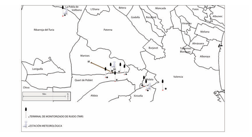
Valencia airport has an Integrated Noise Monitored and Path Tracking System (SIRVAL) that operates automatically and at all times, collecting existing noise levels in areas where the terminals have been installed to monitor Noise (TMR), and, with information from the radar system for airport and flight plans, it represents on a map the places where aircraft are moving in flight, using a geographic information system mapping and digital ortho-photos. The area controlled with radar data covers a radius of 30 miles around the airport.
The SIRVAL has 10 TMR, of which nine are currently installed and running in the following municipalities: Valencia, Manises, Xirivella, Quart de Poblet, Mislata, Aldaia and Ribarroja de Turia. TMR number 10 is portable and will be installed at different locations depending on evaluation needs.
The purpose of SIRVAL is to ensure that aircraft follow the flight paths and procedures established.
-
The term "night" is applicable to the time period between 2300-0700 LT and the term "day" is the time period between 0700-2300 LT.
-
RWY 12: Deviations from the SID will not be cleared until the aircraft is at 9 DME from VLC or has cleared the altitude of 6000 ft, except for propeller-driven aircraft, helicopters, State and hospital aircraft, other than for reasons of operational safety.
RWY 30: Deviations from the SID will not be cleared below the altitude of 6000 ft, except for propeller-driven aircraft, helicopters, State and hospital aircraft, other than for reasons of operational safety.
GROUND ENGINE TEST
Engine tests higher than idle regime will be allowed in H24 in the areas enabled for that purpose.
The clearance request for engine tests at any regime, as well as any consultation on the procedure engine tests, shall be addressed to:
OPERATIONS OFFICE
-
TEL: +34-961 598 535
-
FAX: +34-961 598 537
-
E-mail: vlc.oficinaceops@aena.es
The use of reverse power from idle regime is not allowed during the night period (2300-0700 LT) except for safety reasons, in which case, TWR must be notified immediately.
LOCATION OF NOISE SENSOR SYSTEM
LOCATION |
COOR |
|
|---|---|---|
LAT |
LONG |
|
AEROPUERTO BA |
392848N |
0002850W |
AEROPUERTO ILS |
392905N |
0002824W |
VALENCIA |
392755N |
0002408W |
MANISES |
392904N |
0002735W |
QUART DE POBLET |
392857N |
0002715W |
ALDAIA |
392832N |
0002802W |
XIRIVELLA |
392756N |
0002530W |
MISLATA |
392809N |
0002540W |
RIBARROJA |
393300N |
0003213W |
FLIGHT PROCEDURES
SPEED ADJUSTMENT
Within Valencia TMA, unless otherwise indicated by ATC, the speed on arrival to VALENCIA AD, under radar control, shall be adjusted as specified below:
-
MAX IAS 250 kt at FL100 or below.
-
IAS 220 kt when leaving IAF (CLS or MULAT).
-
IAS 180 kt when leaving IF or when completing the final turn.
-
IAS 160 kt when crossing the FAF/FAP. Aircraft shall maintain this speed till 4 NM from threshold.
-
Aircraft with cruising IAS lower than the aforementioned shall maintain cruising speed up to the corresponding adjustment point.
If this speed adjustment cannot be carried out, pilots shall notify ATC of the speed that can be maintained.
Aircraft will be exempted from complying with these speed limits when performing an instrument continuous descent arrival (CDA) procedure.
RADAR DISPLAY SYSTEM
The use of surveillance radar in providing the Aerodrome Control Service in the Control Tower of Valencia airport is authorised for performing the following functions as established in the Reglamento de la Circulación Aérea in force:
-
Radar assistance to aircraft on final approach;
-
Radar assistance to other aircraft in the vicinity of the aerodrome;
-
Establishing radar separation between successive departing aircraft; and
-
Providing navigation assistance to VFR flights.
LOW VISIBILITY PROCEDURES (LVP) FOR GROUND MOVEMENT
GENERAL
RWY 12/30 is authorised for take-off in low visibility conditions.
-
Low Visibility Procedures (LVP) for take-off will be applied in the following cases:
-
When the minimum weather conditions established below are defined in terms of:
-
RWY visual range (RVR) for RWY 12 and 30, or
-
general visibility in the movement area, for RWY 12 and 30 when anyone of them is 550 m or below, and not below 350 m, in this case all take-offs will be cancelled.
-
-
Landings operations are not allowed when the RVR/visibility are lower than 550 m.
-
Pilots will be informed of the application of Low Visibility Procedures by the appropriate ATC unit and by ATIS system with the text "LOW VISIBILITY PROCEDURE IN OPERATION".
-
Pilots will be also informed by ATC when the application of the LVP are cancelled, which will occur when RVR or the horizontal visibility is above 800 m.
-
During the application of the LVP, operations shall be cancelled except commercial and emergency flights.
GROUND MOVEMENT
The movement of only one aircraft at a time will be authorised in the movement area when the Low Visibility Procedures are being applied.
Pilots will proceed to verify the aircraft position at all times, checking that taxiing is being carried out under conditions of complete safety. If disoriented or in doubt, pilots shall stop the aircraft and immediately notify ATC.
During the activation of the low visibility procedures, the following measures shall be taken:
-
PRKG:
Entry and exit for all PRKG will be carried out with the guidance of the "FOLLOW ME" vehicle.
-
Service roads:
Movements by the authorised service roads will be reduced to a minimum.
The road from SEI to RWY 12/30 will not be used, except in case of emergency. The following service roads will be closed:
-
NORTH apron:
-
From PRKG 6B to 25.
-
From PRKG 6B to 7A.
-
From PRKG 42 to 12.
-
Service road that runs between PRKG 42 and 43.
-
-
SOUTH apron: All roads, except the one that runs from PRKG 141 to 153, near the buildings.
Arrivals:
Aircraft that have already landed will notify "Runway vacated" when the RWY vacated board on the TWY they use to leave has been passed.
At apron entry, aircraft must wait for the arrival of a "FOLLOW ME" vehicle to be guided to the assigned PRKG, and will notify TWR: "FOLLOW ME" in sight.
Departures:
Pilots must request start-up or taxi clearance, indicating the PRKG in which they are located. To establish a better transit sequence, pilots must not request clearance for engine start-up, push-back or taxiing when the RVR values or the weather visibility is below their operational minimums.
When the RVR/visibility is lower than 550 m, and not below 350 m, only one aircraft at a time will be authorised to taxi in the manoeuvring area. In these conditions all the exits from the PRKG will be assisted by a "FOLLOW ME" vehicle in all PRKG.
When a departing aircraft has to return to the apron, the pilot shall inform TWR and await new taxiing instructions.
LVC taxiing routes: Aircraft shall proceed according to the RWY to be used:
NORTH APN:
-
RWY 12: exit via gate GATE-C, taxiing via TWY N2, N3 y N4 up to runway holding position TWY H9, unless ATC instructs otherwise. Except aircraft with code letter E or F parked in PRKG 25, that will accomplish this via GATE-B.
-
RWY 30: exit via GATE-A, taxiing via TWY H3, N1 up to runway holding position TIRIO, except aircraft with code letter D, E or F which shall use the route defined in the procedure for code letter/type E or F aircraft (B748 or A124). Entry into the RWY may be accomplished via TWY H1, T1 only, unless ATC instructs otherwise.
CARGO APN:
-
RWY 12: exit via GATE-D, taxiing via TWY N3 and N4 up to runway holding position TWY H9, unless ATC instructs otherwise.
-
RWY 30: exit via GATE-A, taxiing via TWY N1 up to runway holding position TIRIO, except code letter D, E and F aircraft, which shall use the route defined in the procedure for code letter/type E or F aircraft (B748 or A124). Entry into the RWY may be accomplished via TWY H1 only, unless ATC instructs otherwise.
SOUTH APN:
When Low Visibility Procedures are being applied, operations of aircraft parked on this apron will be cancelled. Only aircraft exempted from ATFCM measures will operate (Flights carrying Heads of State or equivalent, Flights conducting search and rescue operations, Flights authorized by the relevant State authorities, Flights engaged in life-critical emergency evacuation, Flights engaged in fire-fighting services) it shall do as follows:
-
RWY 12: exit via GATE-F, TWY S2, S3, S4, T4 up to runway holding position TWY T4, unless ATC instructs otherwise.
-
RWY 30: exit via GATE-E, TWY M1 up to runway holding position TWY T1, unless ATC instructs otherwise.
R4 APRON: Operations are not allowed.
COMMUNICATIONS FAILURE
Whenever an aircraft or vehicle operating in the manoeuvring area experiences a communication failure, it shall proceed as follows:
-
When it is a departing aircraft, it shall continue along the assigned route to its clearance limit, exercising extreme caution to avoid detours. Aircraft must hold this position and wait for the arrival of a "FOLLOW ME" vehicle to be guided to the assigned PRKG or holding bay.
-
When it is an arriving aircraft, it shall maintain the position in the first segment of the TWY where the ILS-sensitive area is free, and await the arrival of a "FOLLOW ME" vehicle to be guided to the assigned PRKG.
-
When it is a vehicle, it shall hold its position and await the arrival of a "FOLLOW ME" vehicle to be guided to the assigned location.
CONTINUOUS DESCENT OPERATIONS
Depending on traffic situation, and if no need for interrupting the descent is foreseen, aircraft will be cleared to proceed to a standard arrival (STAR), or by means of a "direct to" clearance to an intermediate fix of the STAR, to the IAF, to an intermediate approach fix or to the IF, to the minimum altitude of the IAF or the IF of the instrumental procedure (IAC), in order to allow a continuous descent operation.
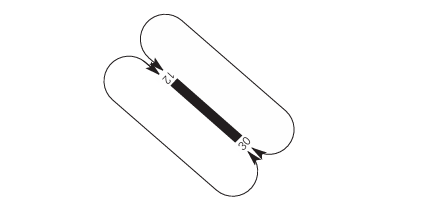
AD TRAFFIC CIRCUIT
ADDITIONAL INFORMATION
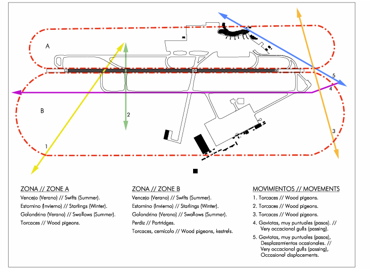
BIRD CONCENTRATION ZONES
AIRPORT VICINITY: FLOWS
Movement 1: Infrequent passage of wood pigeons which cross the runway at the level of H7. Wood pigeons from outside the airport moving to the golf course.
Movement 2: Infrequent passage of wood pigeons which cross the runway at the level of H7. Wood pigeons from the South zone of the airport moving to the golf course.
Movement 3: Infrequent passage of wood pigeons close to the head of RWY 30. Wood pigeons from outside the airport moving from the South towards the locality of Manises.
Movement 4: Very occasional passage of gulls crossing the airport, overflying TWY S1, S2 and S3.
Movement 5: Very occasional passage of gulls close to the head of RWY 12. Gulls from outside the airport moving from the South towards the locality of Manises.
OTHER BIRDS
During the months of April, May and June, swifts and swallows come to the airport to feed.
AERONAUTICAL CHARTS RELATED TO AN AERODROME
The list of charts related to the aerodrome can be found on the link below:
VISUAL SEGMENT SURFACE (VSS) PENETRATION
The instrument approach procedures affected can be found below:
IAC 1 - ILS Z RWY 12: direct approach.
IAC 2 - ILS Y RWY 12: direct approach.
IAC 3 - LOC Z RWY 12: direct approach.
IAC 4 - LOC Y RWY 12: direct approach.
IAC 5 - VOR RWY 12: direct approach.
IAC 6 - RNP Z RWY 12 (LPV ONLY): LPV.
IAC 7 - RNP Y RWY 12: LNAV.
IAC 8 - ILS RWY 30: direct approach.
IAC 9 - LOC RWY 30: direct approach.
IAC 10 - VOR RWY 30: direct approach.
IAC 11 - RNP Z RWY 30 (LPV ONLY): LPV.
IAC 12 - RNP Y RWY 30: LNAV, LNAV/VNAV.