LEBL AD 2 AERODROME DATA
AERODROME LOCATION INDICATOR ANDNAME
LEBL - BARCELONA/Josep Tarradellas Barcelona-El Prat
AERODROME GEOGRAPHICAL AND ADMINISTRATIVE DATA
ARP | 411749N 0020442E. See AD 2-LEBL ADC. | |
Distance and direction from the city | 10 km SW. | |
Elevation | 4 m / 14 ft. | |
Geoid undulation | 49.06 m ± 0.05 m (1). | |
Reference temperature | 29°C. | |
Low average temperature | 9ºC. | |
Magnetic variation | 1ºE (2020). | |
Annual change | 7.5'E. | |
AD administration | Aena. | |
Address | Aeropuerto Josep Tarradellas Barcelona-El Prat. 08820 El Prat (Barcelona). | |
TEL | +34-902 404 704 | |
FAX | +34-932 983 737 | |
AFTN | LEBL | |
Approved traffic | IFR; AD closed for VFR operations, with the exception of ambulance, emergency and State flights, or flights servicing Autonomous Communities and other local Entities, provided these are non-commercial public services. AD closed for helicopter operations, with the exception of: ambulance, emergency and State flights, or flights servicing Autonomous Communities and other local Entities, provided these are non-commercial public services. AD closed for maximum take-off weight (MTOW) operations equal to or less than 2000 kg, with the exception of ambulance, emergency and State flights, or flights servicing Autonomous Communities and other local Entities, provided these are non-commercial public services. AD closed for aircraft operations without suitable radio equipment for continuous two-way radio communication with ATS. | |
Remarks | Local Scheduling Coordination Office.
Payment of charges in cash shall only be made in euros, 1000 euros maximum amount. (1) For all AD points. |
OPERATIONAL HOURS
Airport | H24. | |
Heliport | H24. | |
Customs and Immigration | H24. | |
Health and Sanitation | See GEN 1.4. | |
AIS/ARO | H24 (1). | |
Apron Management Service (SDP) | H24, provided by ATS. | |
MET briefing | H24. | |
ATS | H24. | |
Fuelling | H24. | |
Handling | H24. | |
Security | H24. | |
De-icing | H24. | |
Remarks | (1) Centralised AIO office - International NOTAM Office
Centralised ARO Office geographical area 6
|
HANDLING SERVICES AND FACILITIES
Cargo facilities | Up to 7500 kg. | |
Fuel types | JET A-1. | |
Oil types | AEROSHELL W120, ESSO 100-120. | |
Refuelling capacity | No limitations. | |
De-Icing facilities | Service provided by handling agent. | |
Hangar space | No. | |
Repair facilities | No. | |
Remarks | Ramp agents:
General Aviation agents and General and Business Aviation terminal Managers (FBO):
General Aviation agents:
|
PASSENGER FACILITIES
Hotels | No. | |
Restaurant | Yes. | |
Transportation | Buses, taxis, train, underground and hire cars. | |
Medical facilities | 2 ambulances. First aid. | |
Bank/Post Office | Yes / No. | |
Tourist information | Yes. | |
Remarks | None. |
RESCUE AND FIREFIGHTING SERVICES
Fire category | 10. | |
Rescue equipment | In accordance with the fire category published. | |
Removal of disabled aircraft | Any aircraft operating at the Airport shall grant compliance with "Procedure for the removal of disabled aircraft at Josep Tarradellas Barcelona - El Prat Airport". Capacity of the equipment available by the Airport:
Local contact data for disabled aircraft movement operations: Operational Coordination Centre (CECOPS):
| |
Remarks | Types and quantities of extinguishers normally available:
|
RUNWAY SURFACE CONDITION ASSESSMENT AND REPORTING, AND SNOW PLAN
Types of clearing equipment | Solid de-icer spreader, snowplough. | |
Clearance priorities | Runways, rapid exit taxiways and runway access taxiways, taxiways, apron access and aprons. | |
Use of material for movement area surface treatment | Potassium acetate (KAC), sodium formate (NAFO). | |
Specially prepared winter runways | Not applicable. | |
Remarks | Period of application of snow plan: 15-NOV to 15-MAR. Runway surface condition assessment and reporting in accordance with the Global Reporting Format (GRF) methodology described in AD 1.2.2. Aerodrome in service during all seasons of the year. |
APRONS, TAXIWAYS AND CHECK LOCATIONS/POSITIONS DATA
Apron | Surface: Hydraulic concrete. Strength:
| |
Taxiways | Width: 25 m, EXC:
Surface: Asphalt, EXC:
Strength: > PCN 63/F/A/W/T EXC: ES1, FS1, GS1, HS1, MS1, LS1, M1, N1, S1, T1, Y1, Y5 to Y7, Z5 to Z7, > PCN 75/R/B/W/T; B6 to B10: PCN 55/F/A/W/T; G1 to G3, G10 to G12, K1, K11: PCN 59/R/A/W/T; S11 to S13: PCN 74/R/B/W/T. | |
Check locations | Altimeter: Apron 4 m/13 ft. VOR: No. INS: See AD 2-LEBL PDC. | |
Remarks | TWY centre line: see INSIGNIA and Data Set. |
SURFACE MOVEMENT GUIDANCE AND CONTROL SYSTEM AND MARKINGS
Taxiing guidance system | Lighted position indicators, NO ENTRY signs, mandatory instructions and information signs LGTD, runway-holding position, intermediate holding positions (1), stop bars, no intrusion bars, intermediate holding positions lights, runway guard lights, visual guidance docking system (2) and stands identification markings. | |
RWY markings | Designators, threshold, displaced threshold, centre line, aiming point EXC RWY 20, touchdown zone EXC RWY 20, side stripe, rapid exit taxiway marking indicator on RWY 06L/24R (P1, P2, P3, P4, P5, P6, R1, R2, R3, R4, R5, R6) and RWY 06R/24L (G4, G5, G6, G7, G8, G9). | |
TWY markings | Centre line, side stripe and reflective edge markers. | |
Remarks | (1) Special condition for the requirement relating to the location of the runway holding positions:
(2) See AD 2-LEBL PDC. |
AERODROME OBSTACLES
Obstacles in Approach, Take-Off Climb, Conical, Inner Horizontal, Transitional, Inner Transitional and Balked Landing Surfaces established in ICAO Annex 14; and the areas 2A and 3 established in ICAO Annex 15. Those penetrating these surfaces are identified in the CSV file as "Relevante_Relevant = Si/Yes". | See Item 10 and Data Set. | |
Remarks | See AD 2-LEBL AOC. |
METEOROLOGICAL INFORMATION PROVIDED
MET office | Barcelona EMAe. | |
HR | H24. | |
METAR | Half-hourly. | |
TAF | 24 HR. | |
TREND | Yes. | |
Information | In person, by telephone and fax. | |
Flight documentation/Language | Charts and plain language/Spanish. | |
Charts | Forecast significant, wind and temperature at altitude maps. | |
Supplementary equipment | Clouds, lightning and radar information image display. | |
ATS unit served | TWR, APP. | |
Additional information | Valencia OMAe (LEVA): H24
Barcelona EMAe: H24
| |
Remarks | Aerodrome climatological summary available. Aerodrome warnings available. Aerodrome MET guide avaliable. |
RUNWAY PHYSICAL CHARACTERISTICS
RWY | Direction | DIM (m) | THR PSN | THR ELEV TDZ ELEV | SWY (m) | CWY (m) | Strip (m) | OFZ | RESA (m) | RWY/SWY SFC PCN |
|---|---|---|---|---|---|---|---|---|---|---|
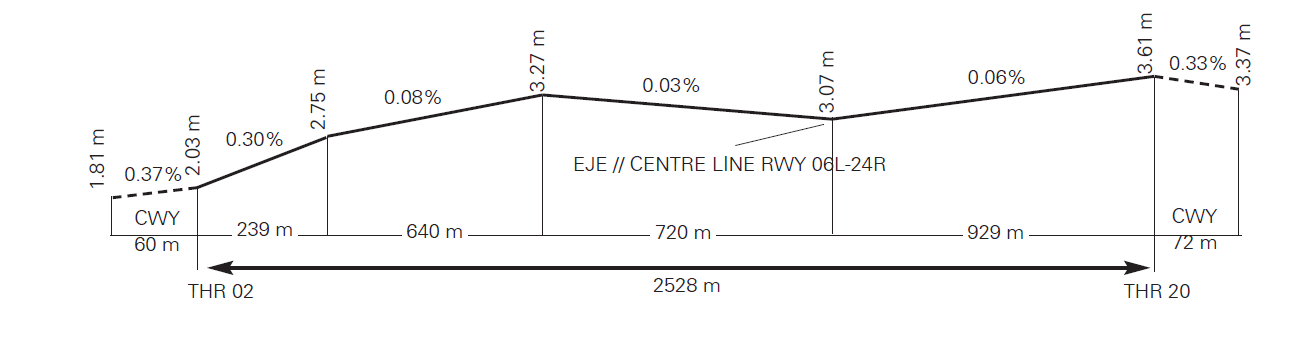
02 | 018.98°GEO 018°MAG | 2528 x 45 | 411715.93N 0020505.38E | THR: 2.0 m / 7 ft TDZ: 3.3 m / 11 ft | No | 72 x 150 | 2648 x 280 (4) | Yes | 240 x 150 (4) | Asphaltic concrete PCN 91/F/A/W/T. SWY: No |
20 (1) | 198.99°GEO 198°MAG | 2528 x 45 | 411833.46N 0020540.75E | THR: 3.6 m / 12 ft TDZ: NO | No | 60 x 150 | 2648 x 280 (4) | No | 240 x 150 (5) | Asphaltic concrete PCN 91/F/A/W/T. SWY: No |
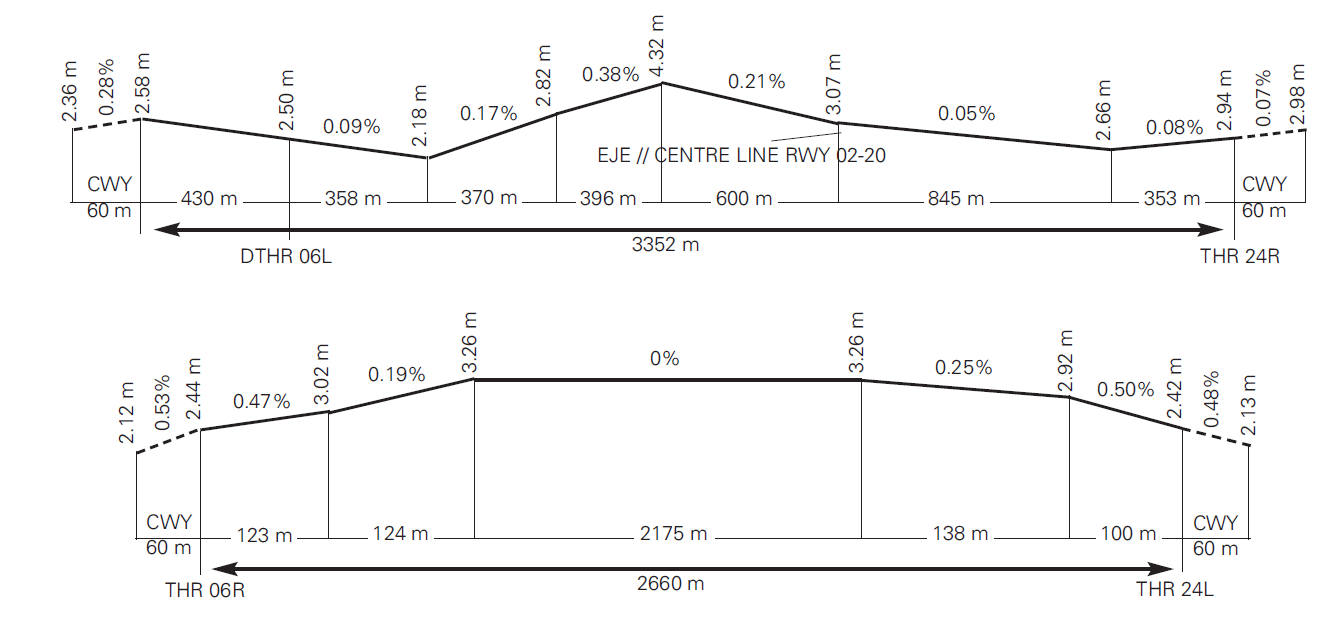
06L (2) | 065.57°GEO 064°MAG | 3352 x 60 | 411741.44N 0020419.00E | THR: 2.5 m / 8 ft TDZ: 3.5 m / 11 ft | No | 60 x 150 | 3472 x 280 (4) | Yes | 240 x 150 (5) | Asphaltic concrete PCN 97/F/A/W/T. SWY: No |
24R (3) | 245.59°GEO 244°MAG | 3352 x 60 | 411820.61N 0020613.40E | THR: 2.9 m / 10 ft TDZ: 2.9 m / 10 ft | No | 60 x 150 | 3472 x 280 (4) | Yes | 240 x 150 (5) | Asphaltic concrete PCN 97/F/A/W/T. SWY: No |
06R | 065.57ºGEO 064ºMAG | 2660 x 60 | 411656.32N 0020427.63E | THR: 2.4 m / 8 ft TDZ: 3.3 m / 11 ft | No | 60 x 150 | 2780 x 280 (4) | Yes | 125 x 150 (4) | Asphaltic concrete PCN 129/F/A/W/T. SWY: No |
24L | 245.59°GEO 244°MAG | 2660 x 60 | 411731.99N 0020611.78E | THR: 2.4 m / 8 ft TDZ: 3.3 m / 11 ft | No | 60 x 150 | 2780 x 280 (4) | Yes | 125 x 150 (4) | Asphaltic concrete PCN 129/F/A/W/T. SWY: No |
Remarks: (1) Not available for landing. (2) THR RWY 06L displaced 430 m. (3) End RWY 24R coordinates: 411735.68N 0020402.19E. (4) Grass soil. (5) Asphaltic concrete and grass soil. | ||||||||||
Profile
DECLARED DISTANCES
RWY | TORA (m) | TODA (m) | ASDA (m) | LDA (m) |
|---|---|---|---|---|
02 | 2528 | 2600 | 2528 | 2528 |
20 | 2528 | 2588 | 2528 | NU |
06L | 3352 | 3412 | 3352 | 2922 |
24R | 3352 | 3412 | 3352 | 3352 |
06R | 2660 | 2720 | 2660 | 2660 |
24L | 2660 | 2720 | 2660 | 2660 |
20 INT UB | 2129 | 2189 | 2129 | – |
06L INT Y5 | 2963 | 3023 | 2963 | – |
06L INT Y6 | 3029 | 3089 | 3029 | – |
06L INT Y7 | 3096 | 3156 | 3096 | – |
06L INT Z5 | 2963 | 3023 | 2963 | – |
06L INT Z6 | 3029 | 3089 | 3029 | – |
06L INT Z7 | 3096 | 3156 | 3096 | – |
24R INT Y2 | 2961 | 3021 | 2961 | – |
24R INT Y4 | 2828 | 2888 | 2828 | – |
24R INT Z2 | 2961 | 3021 | 2961 | – |
24R INT Z3 | 2895 | 2955 | 2895 | – |
24R INT Z4 | 2828 | 2888 | 2828 | – |
Remarks: Available TORA calculated from the intersection of the taxiway edge closest to the start of the runway, and the runway edge. | ||||
APPROACH AND RUNWAY LIGHTING
Runway | 02 | |
Approach | Precision CAT I, 720 m LIH. | |
PAPI (MEHT) | 3° (19.80 m / 65 ft). | |
Threshold | Green. | |
Touchdown zone | No. | |
Runway centre line | 2528 m: 1628 m white+600 m white and red+300 m red. LIH Distance between lights: 15 m. | |
Runway edge | 2528 m: 1928 m white + 600 m yellow. LIH Distance between lights: 50 m. | |
Runway end | Red. | |
Stopway | No. | |
Remarks | All runway lighting systems and associated exit taxiways are equipped with incandescent lighting. |
Runway | 20 | |
Approach | No. | |
PAPI | No. | |
Threshold | No. | |
Touchdown zone | No. | |
Runway centre line | 2528 m: 1628 m white+600 m white and red+300 m red. LIH Distance between lights: 15 m. | |
Runway edge | 2528 m: 1928 m white + 600 m yellow. LIH Distance between lights: 50 m. | |
Runway end | Red. | |
Stopway | No. | |
Remarks | All runway lighting systems and associated exit taxiways are equipped with incandescent lighting. |
Runway | 06L | |
Approach | Precision CAT II/III, 720 m LIH. Threshold identification lights. | |
PAPI (MEHT) | 3° (19.82 m / 65 ft). | |
Threshold | Green. | |
Touchdown zone | 900 m white. | |
Runway centre line | 3352 m: 430 m without lights + 2022 m white + 600 m white and red + 300 m red. LIH Distance between lights: 15 m. | |
Runway edge | 3352 m: 430 m red + 2322 m white + 600 m yellow. LIH Distance between lights: 60 m. | |
Runway end | Red. | |
Stopway | No. | |
Remarks | The runway lighting systems and associated exit taxiways are LED, except for R2, R4 and holding bays which are incandescent. |
Runway | 24R | |
Approach | Precision CAT II/III, 720 m LIH. | |
PAPI (MEHT) | 3° (21.97 m / 72 ft). | |
Threshold | Green. | |
Touchdown zone | 900 m white. | |
Runway centre line | 3352 m: 2452 m white + 600 m white and red + 300 m red. LIH Distance between lights: 15 m. | |
Runway edge | 3352 m: 2752 m white + 600 m yellow. LIH Distance between lights: 60 m. | |
Runway end | Red. | |
Stopway | No. | |
Remarks | Rapid exit taxiway indicator lights (P3, P5, P6, R3, R5, R6). Approach system lights displaced from the runway centre line extension less than 00º15'. The runway lighting systems and associated exit taxiways are LED, except for R3 and R5. The approach lighting system and holding bays are equipped with incandescent lights. |
Runway | 06R | |
Approach | Precision CAT II/III, 900 m LIH. | |
PAPI (MEHT) | 3° (19.89 m / 65 ft). | |
Threshold | Green. | |
Touchdown zone | 900 m white. | |
Runway centre line | 2660 m: 1760 m white + 600 m white and red + 300 m red. LIH Distance between lights: 15 m. | |
Runway edge | 2660 m: 2060 m white + 600 m yellow. LIH Distance between lights: 50 m. | |
Runway end | Red. | |
Stopway | No. | |
Remarks | The G5 rapid exit taxiway lighting systems, runway threshold, and runway end are LED. The rest of runway lighting systems and associated exit taxiways are equipped with incandescent lighting. |
Runway | 24L | |
Approach | Precision CAT II/III, 420 m LIH. | |
PAPI (MEHT) | 3° (19.82 m / 65 ft). | |
Threshold | Green. | |
Touchdown zone | 900 m white. | |
Runway centre line | 2660 m: 1760 m white + 600 m white and red + 300 m red. LIH Distance between lights: 15 m. | |
Runway edge | 2660 m: 2060 m white + 600 m yellow. LIH Distance between lights: 50 m. | |
Runway end | Red. | |
Stopway | No. | |
Remarks | The G8 rapid exit taxiway lighting systems, runway threshold, and runway end are LED. The remaining runway lighting systems and associated exit taxiways are equipped with incandescent lights. |
OTHER LIGHTING, SECONDARY POWER SUPPLY
ABN/IBN | No. | |
WDI | 1 near THR 02, 1 near THR 20, 1 near THR 06R, 1 near THR 24L, 1 near TWY T14, 1 near THR 06L, 1 near THR 24R, 1 near FATO. LGTD. | |
TWY lighting | Centre line. | |
Apron lighting | Floodlighting poles. | |
Secondary power supply | Visual aid systems: Power generators of continuity no break. Terminal building and apron lights: Emergency stand-by equipment with a switch-on time of 21 seconds for T1 and 15 seconds for T2. | |
Remarks | TWY (U, K, J, E, Q, B, AS, BS, CS, DS, ES, FS, GS, HS, LS, NS, PS, RS, TS, VS, ES1, FS1, GS1, HS1, MS1, LS1 and CN) lighting systems are equipped with LED, the remaining TWY are equipped with incandescent lights. The stop bar systems, No Entry lights are LED. PAPIS lighting systems and intermediate holding point are equipped with incandescent lighting. AS, BS, CS, DS, ES, FS, GS, HS, IS, KS, LS, MS, NS, PS, RS, TS, VS, AN, BN and EN GATE lighting systems are LED, and the remaining GATES are equipped with incandescent lighting. |
HELICOPTER LANDING AREA
Position |
| |
Elevation |
| |
Dimensions, surface, maximum weight, marking |
| |
Direction | FATO 09/27 (magnetic heading 090º-270º) and FATO 06/24 (magnetic heading 060º-240º). Arrivals shall operate in FATO 09 and 24. Departures shall operate in FATO 06 and 27. | |
Declared distances | See table (*). | |
Lighting | FATO 09/27 is equipped with LED edge lights for both the FATO and the TLOF. Additionally, FATO 09 features an incandescent approach lighting system and a (6º) APAPI. | |
Remarks |
|
(*)
FATO | TODAH (m) | RTODAH (m) | LDAH (m) |
|---|---|---|---|
09 | NU | NU | 75 |
27 | 75 | 75 | NU |
06 | 75 | 75 | NU |
24 | NU | NU | 75 |
AIR TRAFFIC SERVICES AIRSPACE
Designation | CTR BARCELONA.
| |
| Lateral limits | Airspace limited by two semicircumferences of 12 NM radius joined by its common tangents, centred on points TEBLA (412252N 0021930E) and ASTEK (411232N 0014919E) except Sabadell ATZ. |
Vertical limits Airspace class | MAX ALT VFR SECTOR-FL075...D (3). SFC-MAX ALT VFR SECTOR...E.
| |
Unit Language | BARCELONA APP. ES/EN. | |
Transition altitude | 1850 m / 6000 ft. | |
| Hours of applicability | - |
Remarks | (3) VFR flights not authorized. Traffic with origin/destination authorized heliports and aerodromes shall follow the standard procedures. |
Designation | Area 2 | |
| Lateral limits | Area defined by 412846N 0021100E, arc of circumference of 12 NM radius centred on 411743N 0020507E to 412433N 0015203E, 412720N 0020352E, 412846N 0021100E, except Sabadell ATZ. See ENR 6.5. |
Vertical limits | SFC-FL075.
| |
Airspace class | D (3). | |
Unit Language | - | |
| Transition altitude | - |
| Remarks | (3) VFR flights not authorized. Traffic with origin/destination authorized heliports and aerodromes shall follow the standard procedures. |
Designation | ATZ BARCELONA.
| |
| Lateral limits | Circle radius 8 km centred on ARP (1). |
Vertical limits | SFC-3000 ft HGT (2).
| |
Airspace class | D. | |
Unit Language | BARCELONA TWR. ES/EN. | |
| Transition altitude | - |
| Hours of applicability | - |
| Remarks | (1) Or the ground visibility, whichever is lower. (2) Or up to the cloud ceiling, whichever is lower. |
AIR TRAFFIC SERVICES COMMUNICATION FACILITIES
Service | Call sign | FREQ | HR | Remarks |
|---|---|---|---|---|
APP | Barcelona APP | 121.155 C | H24 | APP-H |
119.105 C | H24 | APP-L | ||
124.705 C | H24 | BACK-UP | ||
125.250 MHz | H24 | APP-H | ||
126.505 C | H24 | APP-H | ||
127.700 MHz | H24 | APP-H | ||
131.125 MHz | H24 | APP | ||
135.280 C | H24 | APP | ||
TWR
| Barcelona TWR
| 118.105 C | H24 | LOCAL ARR/LOCAL ARR+DEP |
118.330 C | H24 | LOCAL DEP | ||
121.500 MHz | H24 | EMERG | ||
121.655 C | H24 | GMC C | ||
121.705 C | H24 | GMC N | ||
121.805 C | H24 | CLR | ||
122.100 MHz | H24 | MIL | ||
122.230 C | H24 | GMC S | ||
122.830 C | H24 | BACK-UP | ||
243.000 MHz | H24 | EMERG | ||
257.800 MHz | H24 | MIL | ||
ATIS
| Barcelona Information
| 118.655 C | H24 | ARR |
121.980 C | H24 | DEP | ||
D-ATIS | Barcelona Information | NIL | H24 | Provision of ATIS information via data link. |
RADIO NAVIGATION AND LANDING AIDS
Facility (VAR) | ID | FREQ | HR | Coordinates | ELEV DME | Remarks |
|---|---|---|---|---|---|---|
DVOR (1º E) | BCN | 116.700 MHz | H24 | 411825.7N 0020628.1E | - | R-096 AVBL at:
R-227 NO AVBL at:
|
DME | BCN | CH 114X | H24 | 411825.9N 0020628.7E | 0 m | R-096 AVBL at:
R-227 NO AVBL at:
R-297: possible loss of signal BTN 62 NM & 74 NM BLW FL160. Overlap with PPN. |
DVOR (1º E) | PRA | 114.300 MHz | H24 | 411659.2N 0020454.7E | - | U/S BTN R-254/R-029 BLW 3000 ft AMSL. |
DME | PRA | CH 90X | H24 | 411658.8N 0020454.3E | 0 m | U/S BTN R-254/R-029 BLW 3000 ft AMSL. |
DVOR (1º E) | SLL | 112.000 MHz | H24 | 413111.5N 0020635.1E | - | R-354 low signal intensity FM 48 NM. |
DME | SLL | CH 57X | H24 | 413112.0N 0020635.1E | 150 m | R-354 low signal intensity FM 50 NM. |
DVOR (1º E) | VLA | 113.150 MHz | H24 | 412033.5N 0013251.7E | - | - |
DME | VLA | CH 78Y | H24 | 412033.4N 0013252.4E | 660 m | - |
DVOR (1º E) | CLE | 115.350 MHz | H24 | 413824.1N 0023804.9E | - | - |
DME | CLE | CH 100Y | H24 | 413824.0N 0023804.2E | 420 m | - |
LOC 02 (1º E) ILS CAT I | BLT | 108.750 MHz | H24 | 411840.0N 0020543.8E | - | 018º MAG / 214 m FM THR 20, NO AVBL FM 25 NM (23.6 NM DME ILS) at 2500 ft AMSL or BLW. |
GP 02 | 330.350 MHz | H24 | 411725.4N 0020505.9E | - | 3º; RDH 15.40 m; at 280 m FM THR 02 & 85 m FM RCL to the left on APCH direction. Full fly-up indications may not be received BLW GP beyond 6º left FM RCL. | |
ILS/DME 02 | BLT | CH 24Y | H24 | 411725.4N 0020505.9E | 9 m | REF DME THR 02. |
LOC 06L (1º E) ILS CAT III | QAA | 110.300 MHz | H24 | 411824.9N 0020626.0E | - | 064° MAG / 320 m FM THR 24R; COV 17 NM AVBL BTN ±35º of RCL at 3000 ft AMSL or ABV; COV 25 NM AVBL BTN ±10º of RCL at 2500 ft AMSL or ABV. |
GP 06L | 335.000 MHz | H24 | 411748.4N 0020430.0E | - | 3°; RDH 16.30 m; at 320 m FM THR 06L & 90 m FM RCL to the left on APCH direction. | |
ILS/DME 06L | QAA | CH 40X | H24 | 411748.4N 0020430.0E | 6 m | REF DME THR 06L. COV 17 NM AVBL BTN -17º & +35º of RCL at 3000 ft AMSL or ABV. |
LOC 24R (1º E) ILS CAT III | BCA | 109.500 MHz | H24 | 411731.9N 0020351.1E | - | 244° MAG / 714 m FM THR 06L. COV 17 NM ±35º FM RCL AVBL at 4000 ft AMSL or ABV. |
GP 24R | 332.600 MHz | H24 | 411819.8N 0020559.1E | - | 3°; RDH 16.2 m; at 314 m FM THR 24R & 115 m FM RCL to the right on APCH direction. | |
ILS/DME 24R | BCA | CH 32X | H24 | 411819.8N 0020559.1E | 9 m | REF DME THR 24R. |
LOC 06R (1º E) ILS CAT III | BLE | 110.750 MHz | H24 | 411734.6N 0020619.5E | - | 064º MAG / 197 m FM THR 24L. COV 17 NM (15.5 NM DME ILS) AVBL BTN ±35º of RCL at 3500 ft AMSL or ABV. |
GP 06R | 330.050 MHz | H24 | 411657.0N 0020441.4E | - | 3º; RDH 16.56 m; at 299 m FM THR 06R & 115 m FM RCL to the right on APCH direction. To 10 NM NO AVBL FM 7º to the right of the RCL. | |
ILS/DME 06R | BLE | CH 44Y | H24 | 411657.0N 0020441.4E | 9 m | REF DME THR 06R. COV 17 NM (15.5 NM DME) AVBL BTN -27º & +35º of RCL at 3500 ft AMSL or ABV. |
LOC 24L (1º E) ILS CAT III | BLW | 111.500 MHz | H24 | 411653.7N 0020420.1E | - | 244º MAG / 195 m FM THR 06R. COV 17 NM ±35º FM RCL AVBL at 4000 ft AMSL or ABV. |
GP 24L | 332.900 MHz | H24 | 411724.6N 0020602.2E | - | 3º; RDH 16.56 m; at 299 m FM THR 24L & 117 m FM RCL to the left on APCH direction. | |
ILS/DME 24L | BLW | CH 52X | H24 | 411724.6N 0020602.2E | 9 m | REF DME THR 24L. |
NDB (1º E) | VNV | 380.000 kHz | H24 | 411238.3N 0014221.1E | - | COV 90 NM. |
LOCAL AERODROME REGULATIONS
RESTRICTIONS ON OPERATIONS
All aircraft without RNAV1 approval or unable to comply with RNAV1 procedures shall notify CLR frequency on first communication.
Additionally, jet aircraft shall notify tower (TWR) frequency on first communication if unable to maintain:
minimum IAS of 190 kt at BL700/BL707 in RWY 02, BL700 in RWY 06R, PERAL/BL800 in RWY 20/24L, or
minimum IAS of 210 kt at BL828/BL829/BL831 in RWY 24R.
Operational restrictions during June, July, August and September: aircraft with a maximum take-off weight (MTOW) of 15000 kg or less shall be restricted and they cannot operate arrivals within the time period 0700-1130. This restriction does not apply to ambulance, emergency and State flights or flights servicing Autonomous Communities and other local Entities, provided they perform non-commercial public services.
Operating restrictions related to noise, see AD 2-LEBL item 21, section 8.
RESTRICTIONS ON APRON USE AND OCCUPANCY
All aircraft operating in the airport must have hired a ramp handling agent.
The classification of regular operators only applies to general aviation, private, business and air taxi traffic.
RESTRICTIONS APPLICABLE TO REGULAR OPERATORS
Regular operators must request departure and arrival slots, in this order, and indicate the aircraft registration number in the request.
In order to obtain the status of a regular operator, the operator must contact bcnoperaciones@aena.es and obtain the corresponding authorisation.
RESTRICTIONS APPLICABLE TO NON-REGULAR OPERATORS
Non-regular operators shall be limited to a maximum stay of 96 hours, and they must request arrival slot and associated departure slot.
In addition, during the aviation summer season, aircraft with a code letter of D or higher, except for air ambulance flights with an STS/MEDEVAC flight plan, search and rescue flights or State flights scheduled to stay between 05:00 and 10:59 UTC, must notify this operation at least 15 days in advance of the arrival date by email to bcnoperaciones@aena.es. In any case, their stay will be limited to a maximum of 36 hours. This notification must be validated by the Operations Division and in all cases the operation will be subject to obtaining the corresponding arrival and departure slots.
RESTRICTIONS AND USE OF RAMP-0
The use of Ramp-0 is for the exclusive use of corporate aviation and private aircraft, to be determined by the declared capacity.
Aircraft with restricted use of push-back on Ramp-0 shall report this via SITA (BCNOOYA) prior to the flight operation, and they must submit the technical certificate accrediting this limitation to the airport via their hired handling agents.
During the summer season, general aviation slots (arrival + departure) will not be coordinated more than 30 days in advance.
FLIGHT PLANS
The LEBL Operations Office may reject flights from/to BARCELONA/Josep Tarradellas Barcelona-El Prat whose EOBT or ETA do not match the assigned airport slot (See GEN 1.2, Section 3).
PREFERENTIAL CONFIGURATIONS
Except when any of the following conditions are present or expected:
Runway, wet or dry, with braking action less than good.
Cloud ceiling below 500 ft over aerodrome elevation.
Visibility lower than 1.9 km (1 NM).
Notified or forecast wind gradient or storms on approach or departure.
Traffic conditions, operational needs, safety situations or the other meteorological conditions preclude it.
ATC will maintain the preferential configurations described below for wind components, including gusts, of up to 10 kt tailwind and/or 20 kt crosswind, and changing may be considered from a tailwind of 7 kt.
Daytime configuration between 0700 and 2300 LT (1):
Preferential: West configuration parallel runways
Arrivals: 24R
Departures: 24L and 24R (2)
No preferential: East configuration parallel runways
Arrivals: 06L
Departures: 06R and 06L (3)
Night time configuration between 2300 and 0700 LT:
Preferential: North configuration intersecting runways (4)
Arrivals: 02
Departures: 06R (5)
No preferential: West configuration single runway
Arrivals: 24L (5)
Departures: 24L (5)
(1) Whenever the traffic demand and the weather and operational conditions so permit, the preferential night time configuration may be extended (north configuration intersecting runways) beyond 0700 LT or to advance it before 2300 LT.
(2) The use of RWY 24R is restricted to those aircraft which can justify that they need more runway length than the available length for RWY 24L, except for ambulance flights with a STS/MEDEVAC flight plan, rescue, State flights or flights servicing Autonomous Communities and other Local Authorities whenever they provide non-commercial public services and request this from ATC, it being mandatory to carry out SID RNAV1 DNP (Non-preferential take-off) departure procedure.
The justification shall contain information about the performance of the aircraft, and state explicitly whether the operation via RWY 06R/24L was not possible for reasons of performance and/or safety. The justification must be sent to Operations at the Airport and Environmental Care and Information Services at the email addresses bcnoperaciones@aena.es and saimbcn@aena.es within a period of 7 calendar days from the date of operation, except for ambulance flights with a STS/MEDEVAC flight plan, rescue and State flights or flights servicing Autonomous Communities and other Local Authorities whenever they provide non-commercial public services that are exempted from this justification.
(3) The use of RWY 06L for take-off is restricted to those aircraft which can justify that they need more runway length than the available length for RWY 06R, except for ambulance flights with a STS/MEDEVAC flight plan, rescue, State flights or flights servicing Autonomous Communities and other Local Authorities whenever they provide non-commercial public services previous request this from ATC, it being mandatory to carry out a SID RNAV1 DNP (Non-preferential take-off) departure procedure.
The justification shall contain information about the performance of the aircraft, and state explicitly whether the operation via RWY 06R/24L was not possible for reasons of performance and/or safety. The justification must be sent to Operations at the Airport and Environmental Care and Information Services at the email addresses bcnoperaciones@aena.es and saimbcn@aena.es within a period of 7 calendar days from the date of operation, except for ambulance flights with a STS/MEDEVAC flight plan, rescue and State flights or flights servicing Autonomous Communities and other Local Authorities whenever they provide non-commercial public services that are exempted from this justification.
(4) Should the RWY 02 cannot be used for arrivals, the west configuration will be used. Only, as a last resort, east configuration will be used with arrivals by RWY 06L.
(5) The use of the RWY 24R or 06L to land or take-off, during night time, for aircraft so need it, is described in paragraph 5 of item 21. Noise abatement procedures.
ATIS messages shall provide information about the runway configuration in use.
MINIMUM RUNWAY OCCUPANCY TIME
ARRIVALS
BARCELONA/Josep Tarradellas Barcelona-El Prat AD has High Intensity Runway Operations (HIRO) procedures. It is mandatory for aircraft to vacate the runway as soon as possible.
To minimize runway occupancy time and the occurrence of "go-arounds", pilots are reminded:
Whenever the conditions of the runway so allow, they should use the following or earlier RET (EXIT for RWY 02), unless otherwise instructed by ATC. Otherwise, they must notify ATC in the first communication with TWR:
AIRCRAFT CATEGORY DUE TO WAKE TURBULENCE | RWY 24L DIST THR-RET | RWY 24R DIST THR-RET | RWY 06L DIST THR-RET | RWY 06R DIST THR-RET | RWY 02 DIST THR-EXIT | ||
|---|---|---|---|---|---|---|---|
RIGHT | LEFT | RIGHT | LEFT | RIGHT | LEFT | LEFT | |
SUPER |
G8 1703 m
|
R6 2053 m |
P6 2112 m |
P1 1864 m |
R1 1661 m
|
G5 1703 m
|
UB 2039 m |
HEAVY | |||||||
MEDIUM (JET) | R5 1703 m | P5 1617 m | |||||
MEDIUM (PROP) | G7 1402 m
| R3 1409
| P3 1275 m
| P2 1305 m | R2 1051 m | G6 1402 m
| |
LIGHT | P4 945 m | R4 751 m | |||||
To vacate runway expeditiously at the fastest speed commensurate with safety.
To adjust runway taxi speed after touchdown when it is evident that the aircraft cannot use the planned RET, avoiding low speeds on the runway.
To ensure fully vacated before stopping.
With the exception of code letter F aircraft, if they cannot contact GMC, after vacating the runway, they should hold short of taxiing until they have established this communication. Code letter F aircraft shall proceed as indicated in point I of Item 20 Local regulations, General taxiing procedures, section 1.2 Push-back and taxiing manoeuvres.
In intersecting runways operations, aircraft landing on RWY 24R shall maintain speed until crossing the intersection with RWY 02/20.
The following RET and EXIT are available, with their associated GMC frequencies:
RWY | DIST THR-RET/EXIT (m) | RET | EXIT | FREQ |
|---|---|---|---|---|
06L | 751 | R4 | - | 121.655 |
06L | 945 | P4 | - | 121.705 |
06L | 1051 | R2 | - | 121.655 |
06L | 1305 | P2 | - | 121.705 |
06L | 1661 | R1 | - | 121.655 |
06L | 1864 | P1 | - | 121.705 |
06L | 2341 | - | Y4 | 121.655 |
06L | 2408 | - | Z3 | 121.705 |
06L | 2922 | - | T1 | 121.705 |
06L | 2922 | - | S1 | 121.705 |
06L | 2922 | - | N1 | 121.655 |
24R | 1275 | P3 | - | 121.705 |
24R | 1409 | R3 | - | 121.655 |
24R | 1617 | P5 | - | 121.705 |
24R | 1703 | R5 | - | 121.655 |
24R | 2053 | R6 | - | 121.655 |
24R | 2112 | P6 | - | 121.705 |
24R | 2972 | - | Z6 | 121.705 |
24R | 2972 | - | Y6 | 121.705 |
24R | 3116 | - | P7 | 121.705 |
06R | 1402 | G6 | - | 122.230 |
06R | 1703 | G5 | - | 122.230 |
06R | 2053 | G4 | - | 122.230 |
06R | 2660 | - | G1 | 122.230 |
24L | 1402 | G7 | - | 122.230 |
24L | 1703 | G8 | - | 122.230 |
24L | 2053 | G9 | - | 122.230 |
24L | 2660 | - | G12 | 122.230 |
02 | 2039 | - | UB | 121.705 |
02 | 2528 | - | U3L | 121.705 |
DEPARTURES
Pilots should be ready for departure when reaching the runway-holding position.
On receipt of line-up clearance pilots should ensure that they are able to taxi and line-up on the runway as soon as the preceding aircraft has commenced either its take-off run or Landing roll.
Pilots, in receipt of a conditional line up clearance on a preceding landing/ departing aircraft (For example: "ABC123, behind the departing Prat Airlines A320, line up and wait RWY 24L, behind"), may cross the holding position (subject to there being no illuminated stop bar) as soon as the preceding landing/departing aircraft has passed their position at the holding bay.
Pilots who require additional separations (due to wake turbulence or other reason), shall notify ATC as soon as possible and before crossing the runwayholding point.
Pilots should be able to commence the take-off run immediately when takeoff Clearance is issued. Pilots unable to comply with this requirement shall notify ATC as soon as possible and await instructions. When appropriate, ATC could cancel the clearance and instruct the aircraft to vacate runway.
The standard intersections to take off are:
RWY 20: UB;
RWY 24R: Y2, Y4, Z2, Z3 and Z4;
RWY 06L: Y5, Y6, Y7, Z5, Z6 and Z7.
For departures from the beginning of RWY 06L and RWY 24R (see "TAKE-OFF FROM INTERSECTION AND START OF RWY 06L/24R").
TWR-APP FREQUENCY CHANGE. IFR traffic: unless otherwise indicated by TWR, when airbone call on the Barcelona APP frequency before crossing 2000 ft. The corresponding frequency is the one described in the SID used according to the corresponding Instrument Flight Standard Departure Chart (SID).
If unable to contact Barcelona APP, contact Barcelona TWR anew.
A-CDM PROCEDURES
DEFINITIONS
A-CDM: Airport Collaborative Decision Making.
TOBT: Target Off-Block Time. Time at which the air carrier or the ground handling agent expects to be ready, with the doors closed, airbridge disconnected and aircraft push-back equipment connected.
TSAT: Target Start-up Approval Time. Estimated start-up time calculated based on the TOBT, taxi time from the stand, the CTOT (if subject to regulation) and the airport operational capacity.
SOBT: Scheduled Off-Block Time.
GENERAL
BARCELONA/Josep Tarradellas Barcelona-El Prat airport applies A-CDM processes in the aircraft departure sequence. The A-CDM processes start three hours prior to the estimated off-block time (EOBT) and end with aircraft take-off. Throughout the process, all flight-related information must be kept up-to-date. The information will be sent automatically to the Network Manager Operations Centre (NMOC) at Eurocontrol and will be used to improve management in assigning calculated take-off time (CTOT).
BARCELONA/Josep Tarradellas Barcelona-El Prat airport applies the FAM (Flight Activation Monitoring) system managed by Eurocontrol. To prevent flight plans from being suspended automatically, the EOBT and TOBT must be kept up-to-date until the request for start-up, following the TSAT, so that the traffic flow enables departure to occur as close to TTOT as possible.
For further information, see AD 1.1, section 5.11 Coordination with the Network Manager Operations Centre (NMOC).
PROCESS
AIRPORT SLOT AND FLIGHT PLAN VALIDATION
Three hours prior to EOBT, the flight plan (FPL) information filed in the A-CDM system will be validated with respect to the airport slot, and the flight destination and the type of aircraft must coincide with the EOBT of the FPL initially filed in both the SOBT. If the information does not match, the system will generate an alarm and an automatic message sent to the airline and ground handling agent, who will have to update the information.
TOBT ALLOCATION
As soon as the air carrier or the ground handling agent has the information on the target off-block time, the TOBT shall be allocated in the A-CDM system. Throughout the process, the TOBT must be updated based on the flight information available to the airline or the ground handling agent.
The EOBT must be in line with the TOBT at all times. If there is more than a 10-minute difference between the two, the system will generate an alarm and an automatic message will be sent to the air carrier and ground handling agent, who must update the TOBT and/or EOBT with a DLA delay message.
TSAT PUBLICATION
Thirty minutes prior to the TOBT, the system will generate a TSAT. This time will be updated (automatically) successively based on the actual start-up sequence, the operational situation and the volume of regulated flights in the sequence.
For regulated flights, the TSAT will be generated based on the CTOT as soon as it is published. Regulated flights must keep the TOBT and EOBT updated, until start-up clearance is requested from ATC.
ENGINE/TURBINE START-UP REQUEST
Aircraft may request ATC authorization from 30 minutes prior to their TOBT, and may request start-up:
from 5 minutes prior to their TOBT for CTOT-regulated flights,
5 minutes prior to their TOBT until 5 minutes after. for the rest of the flights.
The aircraft on first call must provide the following information:
Report the type and series of aircraft, aircraft stand and the ATIS message received,
Communicate the need to perform a cross-bleed start if required,
Report any possible restrictions in complying with local regulations (RNAV equipment, take-off performance, etc.).
ATC Authorization will only be issued between TOBT -30 minutes and TOBT -5 minutes.
Between TOBT -5 and TOBT +5, Barcelona Clearances will take note of the start-up request and when the valid TSAT range is reached, it will transfer traffic to the GMC frequency, which will issue the push-back and/or start-up clearance. If this is not possible, a start-up request will be recorded in the A-CDM system and TSAT information will be provided. The start-up request log is equivalent to the REA message request for flights regulated with CTOT.
Once the start-up request has been noted and TSAT information provided, in order to avoid saturating the CLR frequency, pilots shall refrain from making successive calls before receiving the call from Barcelona Clearances.
If Barcelona Clearances does not receive a start-up request within 5 minutes after TOBT has been given, the flight will lose its TSAT and its start up will not be authorized. It will be required to receive a new updated TOBT and EOBT so that the flight can be sequenced again and receive a new TSAT. The TOBT and/or EOBT update can only be done by the airline or its ground handling agent, so pilots will refrain from making requests to ATC in this regard.
The push-back and/or start-up request must be made on the corresponding GMC frequency and it shall start within 5 minutes of the time of transfer to the GMC frequency. Start-up and push-back clearances can only be given by GMC.
ATC AIP CLEARANCE REQUEST AND START UP VIA DATA LINK
At BARCELONA/Josep Tarradellas Barcelona-El Prat Airport, departure procedures via Data Link (DCL) are applied for ATC clearance services. For more information on the DCL service, see AIP ENR 1.5, section 3. DEPARTING FLIGHTS, ATC Clearance and start-up via data link (DCL).
In case of discrepancies, voice communications will always prevail over data link.
The pilot may request the ATC clearance by DCL in accordance with the start-up procedures (see AD2, item 20, 3.4) with a maximum of 30 minutes before the TOBT (CDM mode) or EOBT (without CDM).
The pilot must request ATC and S/U clearance together via RCD. The RCD message (Departure Clearance Request) must contain the following information:
Aircraft callsign in accordance with the filed flight plan (FPL).
Aerodrome of origin.
Aircraft stand.
Destination aerodrome.
Letter corresponding to the ATIS information received.
ICAO aircraft type designator.
Any free text sent via the RCD by the pilot will not be considered by the ATC. Special requests will always be made via voice communications.
The pilot will receive a message acceptance "RCD RECEIVED" or cancellation "RCD REJECTED".
When communicating approval, Barcelona Clearances will issue a CLD message with the following fields:
Aircraft callsign.
Destination aerodrome.
Assigned runway for departure.
Take-off procedure (SID).
Note: The initial altitude will correspond to the published SID.
SSR code mode A (SQUAWK).
ADT (Approved Departure Time).
Note: ADT = CTOT of the flight, if applicable.
Next frequency.
Current ATIS information letter.
Additional information, including the instruction to contact GMC for start-up clearance or instructions to request said clearance in the event that the start-up clearance parameters indicated in AD2, Item 20, 3.4. are not fulfilled.
When a CLD message is sent within the valid TOBT and TSAT range, ATC clearance with and instructions to contact GMC will be given. If not ready for start-up, the pilot shall not accept the frequency change and shall send a new message or contact the CLR controller by voice when ready.
When an FSM message of the type "REVERT TO VOICE PROCEDURES" is received, communication via data link will be terminated and must be reverted to voice procedures.
When a CLD message is received, the pilot:
If any inconsistencies in the received message are detected, the pilot must revert to voice procedures and request a new authorization.
If the pilot considers the authorization CLD message to be correct, he/she must respond via data link with a CDA message (Departure Clearance Echoback).
If a CDA message is not received by the pilot within the waiting time, or a CDA that is inconsistent with the previous CLD message is received, communication via data link will be terminated and a "CDA REJECTED" message will be received in the FMS.
When the correct CDA message is received, the ATC system will send the aircraft a "CLEARANCE CONFIRMED" message in the FMS and will terminate the communication via data link.
The push-back and/or start-up request must be made on the corresponding GMC frequency and it shall start within 5 minutes of the time of transfer to the GMC frequency. Start-up and push-back clearances can only be given by GMC.
REVERT TO VOICE PROCEDURES
Upon receiving a message of the type "REVERT TO VOICE PROCEDURES", or in the event of any inconsistency in the authorization received, the pilot will contact via voice communications with the controller and request a new authorization.
STANDARD TAXIING PROCEDURES
GROUND MOVEMENT
GENERAL
All surface movements of aircraft, towed aircraft, personnel and vehicles on the manoeuvring area are subject to prior ATC clearance.
Guidance service by "FOLLOW ME" vehicle is provided for aircraft on the apron in the following cases:
Towed aircraft.
Corporate aviation aircraft.
Code letter D or higher aircraft heading to parking positions without availability of Visual Docking Guidance System (SVGA).
Helicopters.
Aircraft heading to Ramp 32 (see AD 2-LEBL PDC).
At the discretion of the aerodrome, during special operations or when required by operational safety considerations.
Upon the aircraft pilot's request, when adverse weather conditions reduce visibility, or for other duly justified reasons.
The marshalling service for parking is provided by the driver of the "FOLLOW ME" vehicle in the following cases:
Corporate aviation aircraft.
Code letter D or higher aircraft heading to parking positions without availability of Visual Docking Guidance System (SVGA).
Helicopters.
Stands on Ramp 32 (see AD 2-LEBL PDC).
At the discretion of the aerodrome, during special operations or when required by operational safety considerations.
Aircraft allocated to contact stands at the terminal building where a Visual Docking Guidance System (VDGS) is not provided, unserviceable, or temporarily out of use.
The marshalling service for stand exit is provided by the ground handling agent.
Barcelona Ground Movement Control (GMC) is responsible for:
Control of all aircraft, personnel and vehicle movements on the manoeuvring area except for the runway or runways in use;
Issuing clearances and instructions for towed push-back and taxiing of aircraft and vehicles;
Reporting the stands assigned to aircraft by the Operational Coordination Centre (CECOPS).
Avoidance of collisions with other aircraft or obstacles is the responsibility of:
Pilots taxiing in the apron and taxiway segments not visible from TWR (see AD 2-LEBL GMC);
Ground handling agents during the aircraft towing.
PUSH-BACK MANOEUVRING AND TAXIING
Aircraft must commence taxiing on the apron using the minimum necessary thrust.
Aircraft must be ready for towed push-back or taxiing within 5 minutes of the GMC frequency transfer time, otherwise the pilot shall inform ATC.
Aircraft with wingspan equal to or greater than 52 m or vertical empennage equal to or greater than 14.86 m, shall report this in the first call to GMC.
When an aircraft is ready to the push-back and/or taxiing, it shall request clearance on the taxiing frequency indicated in AD 2-LEBL GMC before this may start.
Powerback push-back is prohibited.
At all aircraft stands in contact with the terminal building, it is prohibited to start engines at a rate above idle until the aircraft has completed the pushback and has been expressly cleared to do so.
When requesting start up, if an aircraft has reported the need for performing a cross-bleed engine start, this shall be requested on the taxiing frequency indicated in AD 2-LEBL GMC.
In parallel runways operation:
G.1. Under normal conditions aircraft will taxi following the routes described in section 2 (TAXIING ROUTES) corresponding to the configuration in use.
G.2. Under certain circumstances, ATC may authorize an aircraft to shorten the route by crossing the runway in use. In this case the crew must be in a position to accelerate the crossing of the runway in use and may not taxi at low power ("reduced engine taxi'), notifying ATC otherwise.
G.3. During the summer season, G.2 will not be applicable to general aviation aircraft coming from Ramps 0 and 1, except for State flights, ambulance flights with a MEDEVAC flight plan, rescue flights or flights providing non-commercial services to public entities.
In all cases GMC shall establish the appropriate apron GATE.
When vacating the runway, if taxiing instructions have not been received, all aircraft except code letter F aircraft, shall stop at the end of the exit taxiway segment.
Code letter F aircraft vacating it via:
R6: Shall halt on TWY N10 and hold short of GATE ES.
R1: Shall halt on TWY N4 and hold short of RWY 02/20.
Y6: Shall halt on TWY N13 and hold short of GATE CS.
Y2/Y4: Shall halt on TWY N3 and hold short of TWY NM.
To reduce the risk of runway incursions by aircraft, pilots shall base the continuity of taxiing on the possibility of following the green taxiway centre line lights (when these are switched on). In the event of losing this visual reference, they shall stop taxiing, notify their position and request instructions from ATC. The taxiing instructions shall include clearance to cross active and non-active runways. If they do not receive this clearance, aircraft shall hold at the holding position of the appropriate runway.
Taxiing of Aircraft: A388, A346, B748 and AN124.
K1. On straight sections of taxiways, the yellow centreline shall be followed, without deviating from it.
K2. During manoeuvres between taxiways, discretionary overshooting will be performed.
K3. Aircraft shall initiate movement with minimum thrust and taxi with external engines at idling speed.
K4. The taxiing restrictions for A388, B748 and AN124 aircraft are indicated in AD 2-LEBL GMC 1.5.
Aircraft must approach as close as possible to the runway-holding position or intermediate holding position (see AD 1.1 item 5.7). Pilots taxiing behind an aircraft stopped at a runway-holding position or intermediate holding position are responsible for keeping a safe distance from it. If there is any doubt about whether an aircraft located at a runway-holding position or intermediate holding position can be overtaken safely, the taxiing aircraft must stop, notify ATC and request alternative instructions.
RESTRICTION ON TAXIING
GENERAL
Aircraft classification according to chapter 1 of annex 14 ICAO:
Code letter F: Wingspan 65 m up to but not including 80 m.
Code letter E: Wingspan 52 m up to but not including 65 m.
Code letter D: Wingspan 36 m up to but not including 52 m.
Code letter C: Wingspan 24 m up to but not including 36 m.
Code letter B: Wingspan 15 m up to but not including 24 m.
Code letter A: Wingspan up to but not including 15 m.
RUNWAY-HOLDING POSITIONS
Maximum aircraft entering in Y5, Y6, Y7, Z2, Z3, Z4, Z5, Z6, Z7:
TWY | Y5/Z4/Z5 | Y6/Z3/Z6 | Y7/Z2/Z7 |
|---|---|---|---|
MAX CODE LETTER | D | D | D |
C | E | C | |
E | C | E | |
B | F | B | |
F | B | F |
Maximum aircraft taxiing via N13 with aircraft stopped in Y5, Y6, Y7:
TWY | Y5/Y6/Y7 | N13 |
|---|---|---|
MAX CODE LETTER | F | - |
E | - | |
D | - | |
C | - | |
B | C |
Maximum aircraft taxiing via CS/BS with aircraft stopped in Y5/Y7:
TWY | Y5/Y7 | CS/BS |
|---|---|---|
MAX CODE LETTER | F | C |
E | C | |
D | E | |
C | F |
Maximum aircraft taxiing via N with aircraft stopped in Y4/Y2/Y1/N1/E6/D4:
TWY | Y4/Y2/Y1/N1/E6/D4 | N |
|---|---|---|
MAX CODE LETTER | F | - |
E | - | |
D | - | |
C | C | |
B | D |
Maximum aircraft taxiing via M with aircraft stopped in runway-holding positions CAT II/III of Y4 and Y2:
TWY | Y4/Y2 CAT II/III | M |
|---|---|---|
MAX CODE LETTER | F | C |
E | C | |
D | D | |
C | F |
Maximum aircraft taxiing between T2 and S1 with aircraft stopped in T1:
TWY | T1 | T2-S1 |
|---|---|---|
MAX CODE LETTER | F | - |
E | - | |
D | C | |
C | F |
Maximum aircraft taxiing between U1 and S5 with aircraft stopped in S4 nosed the East:
TWY | S4 | U1-S5 |
|---|---|---|
MAX CODE LETTER | F | E |
E | E | |
D | FE |
Maximum aircraft taxiing between T13 and S14 with aircraft stopped in T14:
TWY | T14 | T13-S14 |
|---|---|---|
MAX CODE LETTER | F | C |
E | C | |
D | D | |
C | F |
Maximum wingspan of aircraft entering in U:
TWY | U3L | U3R |
|---|---|---|
MAX CODE LETTER | B | D |
C | C | |
D | B | |
E | A | |
F | - |
Aircraft with code letter E or greater will take off via RWY 20 from TWY U3L only.
Maximum aircraft taxiing between U1 and U2 with aircraft stopped in UB:
TWY | UB | U1-U2 |
|---|---|---|
MAX CODE LETTER | B | F |
C | E | |
D | D |
Maximum aircraft taxiing between J5 and E3 with aircraft stopped in E2:
TWY | E2 | J5-E3 |
|---|---|---|
MAX CODE LETTER | F | - |
E | - | |
D | B | |
C | E | |
B | F |
Maximum aircraft entering in G:
TWY | G1/G12 | G2/G11 | G3/G10 |
|---|---|---|---|
MAX CODE LETTER | - | F | C |
D | E | D | |
E | D | E | |
F | C | E |
Maximum aircraft taxiing via K1 with aircraft stopped in G3:
TWY | G3 | K1 |
|---|---|---|
MAX CODE LETTER | A | F |
B | E | |
C | D | |
D | C | |
E | - |
Maximum aircraft taxiing via K1 with aircraft stopped in G2:
TWY | G2 | K1 |
|---|---|---|
MAX CODE LETTER | A | F |
B | E | |
C | D | |
D | C | |
E | - | |
F | - |
Maximum aircraft taxiing via K11 with aircraft stopped in G10:
TWY | G10 | K11 |
|---|---|---|
MAX CODE LETTER | A | E |
B | D | |
C | C | |
D | - | |
E | - |
Maximum aircraft taxiing via K11 with aircraft stopped in G11:
TWY | G11 | K11 |
|---|---|---|
MAX CODE LETTER | A | E |
B | D | |
C | C | |
D | - | |
E | - | |
F | - |
Maximum aircraft taxiing via rapid exit taxiways G4 or G9 with aircraft stopped in G3 or G10:
TWY | G3/G10 | G4/G9 |
|---|---|---|
MAX CODE LETTER | E | B |
D | C | |
C | E | |
B | F |
Maximum aircraft entering in M1, N1, Y1, S1 and T1:
TWY | M1/S1 | N1/T1 | Y1 |
|---|---|---|---|
MAX CODE LETTER | E | E | E |
F | D | F | |
D | F | D |
TAXIING
Between GATE CN and S2/T2 the following taxiing restrictions are established between aircraft situated on TWY S and T:
TWY | S | T |
|---|---|---|
MAX CODE LETTER | D | F |
E | E | |
F | D |
Between GATEs CN and KN the following taxiing restrictions are established between aircraft situated on TWY B, S and T:
TWY | B | S | T |
|---|---|---|---|
MAX CODE LETTER | B | F | C |
C | E | D | |
D | D | E | |
E | C | F |
Between GATE KN and S14/T14 the following taxiing restrictions are established between aircraft situated on TWY S and T:
TWY | S | T |
|---|---|---|
MAX CODE LETTER | D | F |
E | E | |
F | D |
During engine testing on TWY T2, taxiing via S1 is not allowed. If the aircraft in TWY T2 is not testing engines or has finished this, the following taxiing restrictions are established in S1:
TWY | T2 | S1 |
|---|---|---|
MAX CODE LETTER | C | F |
D | D | |
E | - | |
F | - |
During engine testing on the TWY N1, taxiing via TWY Y1 and between TWY M2 and M1 is not allowed. If the aircraft in TWY N1 is not testing its engines or has finished this, there are no taxiing restrictions between TWY M2 and M1, but taxiing via TWY Y1 is not allowed.
Between M16 and N16 the following taxiing restrictions are established:
TWY | M16 | N16 |
|---|---|---|
MAX CODE LETTER | F | D |
E | E | |
D | F |
Between M15/N15 and GATE DS the following taxiing restrictions are established between aircraft situated on TWY L, M and N:
TWY | L | M | N |
|---|---|---|---|
MAX CODE LETTER | B | F | C |
C | E | D | |
D | D | E | |
E | C | F |
Push-back to TWY L from PRKG 214 is permitted for aircraft of maximum wingspan 61 m.
Between GATE DS and TWY E5, the following taxiing restrictions are established between aircraft situated on TWY M and N:
TWY | M | N |
|---|---|---|
MAX CODE LETTER | F | D |
E | E | |
D | F |
Between TWY E5 and M2/N2, there are no taxiing restrictions between aircraft situated on TWY M and N:
TWY | M | N |
|---|---|---|
MAX CODE LETTER | F | F |
Taxiing restrictions are established between aircraft situated on TWY J7/J8 and K8:
TWY | J7/J8 | K8 |
|---|---|---|
MAX CODE LETTER | F | D |
E | E | |
D | F |
Between GATE PS and TWY Q12 the following taxiing restrictions between aircraft are established on TWY Q and K:
TWY | Q | K |
|---|---|---|
MAX CODE LETTER | E | F |
F | E |
At GATE BN taxiing restriction is established for aircraft with a maximum code letter of B.
Simultaneous manoeuvres of aircraft with code letter D or below on TWY M and N, do not have any taxiing restrictions.
Simultaneous manoeuvres of aircraft with code letter D or below on TWY B, S and T, do not have any taxiing restrictions.
TWY B, L and Q are used to access to the stand.
On TWY B6 to B11, L11 to L8, Q6, Q7, Q8, P2, P6, P7, G3, G10, U3R, U4, U5, U6 and U7 taxiing restriction is established for aircraft with a maximum code letter E.
On TWY L12 to L14, taxiing restriction is established for aircraft with a maximum code letter D.
On TWY ES1, FS1, GS1, HS1, LS1 and MS1 taxiing restriction is established for aircraft with a maximum code letter C.
The taxiing of aircraft with vertical stabilisers in the tail empennage equal to or greater than 16.46 m from S16 to M16 or vice versa, is incompatible with landings on RWY 06L.
The taxiing of aircraft with vertical stabilisers in the tail empennage equal to or greater than 14.86 m from T14 to N16 or vice versa, is incompatible with landings on RWY 06L.
The taxiing of any aircraft from S14 to M16 or vice versa, and from T14 to N16 or vice versa, is incompatible with take-offs from RWY 24R.
TAXIING ROUTES
Below, reference is made to the general directions of taxiing expected as determined by the normal configurations. In any event, pilots shall follow the taxiing instructions provided by ATC.
PARALLEL RUNWAY OPERATION
WEST CONFIGURATION (WRL). See AD 2-LEBL GMC 1.1
GENERAL
Arrivals by RWY 24R.
Departures by RWY 24L.
The general taxiing direction in TWY S is to the West.
The general taxiing direction in TWY T is bidirectional.
The general taxiing direction in TWY N is bidirectional.
The general taxiing direction in TWY M is to the East.
The general taxiing direction in TWY E is to the South.
The general taxiing direction in TWY D is to the South
The general taxiing direction in TWY J is to the West.
The general taxiing direction in TWY K is to the East (K11 to K8 bidirectional).
ARRIVALS
The following taxiing routes are established for aircraft arriving by RWY 24R:
Terminal T1
Aircraft with stands at Terminal T1 shall vacate RWY 24R and follow the ATC instructions corresponding to their stand:
Ramp-9: Shall vacate RWY 24R to the North and follow ATC instructions.
Ramps-10, 11, 12 and 16: Shall vacate RWY 24R to the South and shall taxi via TWY N/M to the GATE indicated by ATC.
Ramps 13, 14, 15 and 17: Shall vacate RWY 24R to the South and shall taxi via TWY N/M, E and J/K to the GATE indicated by ATC.
Terminal T2
Aircraft with stand at Terminal T2 shall vacate RWY 24R to the North and they shall follow ATC instructions.
DEPARTURES
Unless otherwise instructed by ATC, aircraft shall exclusively use G1 and G2 at RWY 24L holding position. G3 only available if instructed by ATC.
The following taxiing routes are established for aircraft departing from RWY 24L:
Terminal T1
Ramp-9: Join through the GATE indicated by ATC, to S, M, E or D and K up to holding position RWY 24L.
Ramps-10, 11, 12 and 16: Join through the GATE indicated by ATC, to M, E or D and K up to holding position RWY 24L.
Ramps-13, 14, 15 and 17: Join through the GATE indicated by ATC, to K up to holding position RWY 24L.
Terminal T2
Join through the GATE indicated by ATC, to U, S, M, E or D and K up to holding position in RWY 24L
EAST CONFIGURATION (ELR). See AD 2-LEBL GMC 1.2
GENERAL
Arrivals by RWY 06L.
Departures by RWY 06R.
The general taxiing direction in TWY S is to the West.
The general taxiing direction in TWY T is bidirectional.
The general taxiing direction in TWY N is to the West.
The general taxiing direction in TWY M is to the East.
The general taxiing direction in TWY E is to the South.
The general taxiing direction in TWY J is to the West.
The general taxiing direction in TWY K is to the West.
ARRIVALS
The following taxiing routes are established for aircraft arriving by RWY 06L:
Terminal T1
Aircraft with stand in Terminal T1 shall leave RWY 06L and they shall follow the ATC instructions belows, depending on their stand:
Ramp-9: Shall vacate RWY 06L to the North and follow ATC instructions.
Ramps-10, 11, 12 and 16. Shall vacate RWY 06L to the South and shall taxi via TWY N to the GATE indicated by ATC.
Ramps-13, 14, 15 and 17.:Shall vacate RWY 06L to the South and shall taxi via TWY N, E and J/K to the GATE indicated by ATC.
Terminal T2
Aircraft with stand on Terminal T2 shall vacate RWY 06L to the North and they shall follow the ATC instructions.
DEPARTURES
Unless otherwise instructed by ATC, aircraft shall exclusively use G11 and G12 at RWY 06R holding position. G10 only available if instructed by ATC.
The following taxiing routes are established for aircraft departing from RWY 06R:
Join through the GATE indicated by ATC, to U, S, M, E, J and K up to holding position of RWY 06R.
OPERATION WITH INTERSECTING RUNWAYS
NORTH CONFIGURATION (ENR). See AD 2-LEBL GMC 1.3
GENERAL
Arrivals by RWY 02.
Departures by RWY 06R.
The general direction of taxiing in TWY S is towards the West.
The general direction of taxiing in TWY T is towards the East.
The general direction of taxiing in TWY N is towards the West.
The general direction of taxiing in TWY M is towards the East.
The general direction of taxiing in TWY E is towards the South.
The general direction of taxiing in TWY J is towards the West.
The general direction of taxiing in TWY K is towards the West.
ARRIVALS
Aircraft shall preferably vacate RWY 02 via TWY UB, notifying ATC if they need to exit by the runway end.
The following taxiing routes are established for aircraft landing by RWY 02:
Terminal T1
Ramp-9: Incorporation into U and S up to the GATE indicated by ATC.
Ramps-10, 11, 12 and 16: Incorporation into U and S up to S7, E and N up to the GATE indicated by ATC.
Ramps-13, 14, 15 and 17: Incorporation into U and S up to S7, E and J/K up to the GATE indicated by ATC.
Terminal T2
Incorporation into U and S up to the GATE indicated by ATC.
DEPARTURES
Unless otherwise instructed by ATC, aircraft shall exclusively use G11 and G12 at RWY 06R holding position. G10 only available if instructed by ATC.
The following taxiing routes are established for aircraft taking off by RWY 06R:
Terminal T1
Ramp-9: Incorporation, via the GATE indicated by ATC, into T up to T8, E, J and K up to the holding position of RWY 06R.
Ramps-10, 11, 12 and 16: Incorporation, via the GATE indicated by ATC, into M, E, J and K up to the holding position of RWY 06R.
Ramps-13, 14, 15 and 17: Incorporation, via the GATE indicated by ATC, into J and/or K up to the holding position of RWY 06R.
Terminal T2
Incorporation, via the GATE indicated by ATC, into S up to S7 or T up to T8, E, J and K up to the holding position of RWY 06R.
OPERATION WITH SINGLE RUNWAY
WEST CONFIGURATION (WLL). See AD 2-LEBL GMC 1.4
GENERAL
Arrivals by RWY 24L.
Departures by RWY 24L.
The general direction of taxiing in TWY S is towards the East.
The general direction of taxiing in TWY T is towards the West.
The general direction of taxiing in TWY N is towards the West.
The general direction of taxiing in TWY M is towards the East.
The general direction of taxiing in TWY E is towards the North.
The general direction of taxiing in TWY D is towards the South.
The general direction of taxiing in TWY J is towards the East.
The general direction of taxiing in TWY K is towards the East (K11 to K8 bidirectional).
ARRIVALS
Aircraft landing by RWY 24L shall notify ATC if they need to vacate it by the runway end.
The following taxiing routes are established for aircraft landing by RWY 24L:
Terminal T1
Ramp-9: Incorporation into K, J, E and T up to the GATE indicated by ATC.
Ramps-10, 11, 12 and 16: Incorporation into K, J, E and N up to the GATE indicated by ATC.
Ramps-13, 14, 15 and 17: Incorporation into K up to the GATE indicated by ATC.
Terminal T2
Incorporation into K, J, E and S or T up to the GATE indicated by ATC.
DEPARTURES
Unless otherwise indicated by ATC, aircraft shall exclusively use G1 and G2 at the RWY 24L holding position.
The following taxiing routes are established for aircraft taking off by RWY 24L:
Terminal T1
Ramp-9: Incorporation, via the GATE indicated by ATC, into S up to S7, D and K up to the holding position of RWY 24L.
Ramps-10, 11, 12 and 16: Incorporation, via the GATE indicated by ATC, into M up to M6, D and K up to the holding position of RWY 24L.
Ramps-13, 14, 15 and 17: Incorporation, via the GATE indicated by ATC, into K up to the holding position of RWY 24L.
Terminal T2
Incorporation, via the GATE indicated by ATC, into S up to S7 or T up to T6, D and K up to the holding position of RWY 24L.
TAKE-OFF FROM INTERSECTION AND START OF RWY 06L/24R
Pilots who request take-off from the start of RWY 06L or RWY 24R, must inform ATC during the first contact with GMC.
The standard intersections are: Z2, Z3, Z4, Y2 or Y4 for RWY 24R and Z5, Z6, Z7, Y5, Y6 or Y7 for RWY 06L.
When pilots request this, the ATC shall consider that the take-off distance available from the intersection proposed is the minimum necessary for this particular aircraft.
RESTRICTIONS ON STANDS
The use of the 400 Hz facilities of the airport is obligatory. The use of the air conditioning (A/C) facilities will be obligatory if there is a need for cooling inside the aircraft.
The use of the Auxiliary Power Unit (APU) of the aircraft is prohibited in the stands subject to two different time windows:
From 0700 to 2300 LT:
Positions in contact with the terminal: Within the period from 2 minutes after chocks are placed upon arrival to 6 minutes before the departure TOBT. The aircraft APU may only be used when the fixed units are not in operation or do not possess appropriate A/C capacity for that model of aircraft, and the mobile units are not available.
Remote positions: The use of the APU is prohibited, except 10 minutes after chocks are placed upon arrival and 10 minutes before the departure TOBT, except for wide-body aircraft, for which use is permitted 50 minutes before departure and 15 minutes after arrival. The aircraft APU may only be used when the mobile units are not available.
From 2300 to 0700 LT:
Positions in contact with the terminal: Within the period from 2 minutes after chocks are placed upon arrival to 5 minutes before the chocks are removed for departure. The APU may only be used when the fixed units are not in operation and the mobile units are not available.
Remote positions: The use of the APU is prohibited, except 10 minutes after chocks are placed upon arrival and 10 minutes before the chocks are removed for departure, except for wide-body aircraft, for which use is permitted 50 minutes before departure and 15 minutes after arrival. The aircraft APU may only be used when the mobile units are not available.
AIRCRAFT DE-ICING
An aircraft de-icing area has been established for aircraft up to 52 m wingspan on stands of Ramp-17. De-icing of aircraft with code letter E or greater will be done on the stands where the aircraft are parked.
OPERATION IN DE-ICING AREA (WINGSPAN LESS THAN 52 m)
When the pilot request clearance to start up, the need for de-icing operation shall be reported. Start up authorization may be cleared according to the operational needs and the sequence of requests for de-icing instead of TSAT (Target Start up Approval Time).
Pilots shall maintain permanent watch on the GMC-S frequency corresponding to the de-icing area.
Once the de-icing operation has finished, pilots shall notify on the GMC frequency corresponding to the de-icing area that they are ready for departure and, when cleared, they shall leave the de-icing area as soon as possible.
Clearance to enter the de-icing area shall be granted once the previous aircraft has vacated it.
Pilots in command shall ensure that the aircraft is properly located on the stand in order to safeguard the movement of the de-icing equipments through the area.
De-icing operations of aircraft shall be carried out with the engines idling and ready to take-off, or with engines off using the aircraft APU. For the de-icing operation of a 4 engines aircraft, the agent in charge of the de-icing operation may require the pilot to turn off some of the outer engines.
When an aircraft cannot leave the de-icing area under its own power, the operator responsible for it is obliged to remove it immediately from the mentioned area according to the established procedure with its handling agent.
An operator of the handling agent (or the company, if required by its own procedures) shall contact the pilot in command of the aircraft by means of JACK communication, reporting the de-icing service conclusion.
OPERATION OF MODE S TRANSPONDER WHEN THE AIRCRAFT IS ON THE GROUND
In order to cooperate with the Mode-S based Advanced Surveillance System, aircraft operators intending to use BARCELONA/Josep Tarradellas Barcelona-El Prat airport shall ensure that the Mode S transponder is able to operate when the aircraft is on the ground.
Pilots shall:
Select AUTO mode and assigned Mode A code.
If AUTO mode is not available, select ON (e.g. XPDR) and assigned Mode A code:
From the request for towed push-back or taxi, whichever is earlier.
After landing, continuously until the aircraft is fully parked in its stand.
When the aircraft is fully parked, they shall select STBY.
Whenever the aircraft is capable of reporting Aircraft Identification (e.g. callsign used in flight), this should also be entered (by means of the FMS or the Transponder Control Panel) from the request for towed push-back or taxi, whichever is earlier. Air crew must use the ICAO defined format to enter the Aircraft Identification (e.g. BAW123, AFR6380, ...).
In order to ensure that the performance of systems based on SSR frequencies (including airborne TCAS units and SSR radar) is not affected, TCAS should not be selected before receiving the clearance to line-up and wait, and should be deselected after vacating the runway.
Aircraft taxiing without flight plan should select Mode A code 2000.
OPERATIONAL SAFETY REPORTS
Pilots/operator shall report to the airport as soon as possible any accidents, incidents, occurrences or events which may have a potential operational impact and in which they have been involved or witnessed.
The aim of these reports is the compilation of the information in order to improve operational safety, independently of the mandatory reporting of the occurrence to the appropriate aeronautical authority. Data may be sent in any format, including at least the following information:
Date and time.
Site.
Parties involved (data used to identify vehicles, aircraft … involved).
Companies implicated.
Description of the facts.
Any other data considered relevant (e.g. lighting conditions, weather, phase of the operation such as take-off/landing/stopover, pavement conditions …).
Contact e-mail address of the airport, for the reception of operational safety reports, is the following:
In addition to notifying the airport by means of the indicated system, it is necessary to send at least basic data of the accident, incident, occurrence or event to the air traffic control service provider (ATC).
In the specific instance of safety reports related with the air traffic control service provider (manoeuvring area, flight phases and ATS airspace) these may be sent to the e-mail address:
EMERGENCY MANAGEMENT
Air carriers without a designated airport representative for the purpose of coordinating emergency response actions will not be allowed to operate at airports managed by Aena SME S.A. and Aena Sociedad Concesionaria del AIRM SME S.A. As of February 2025, this requirement is applicable to regular passenger revenue flight and chartered flight companies that perform 24 or more arrivals or departures at the airport within three consecutive months.
USE OF ENGLISH LANGUAGE IN RADIO COMMUNICATIONS
Whenever there is a pilot on the frequency/frequencies in use in the manoeuvring area who does not speak Spanish, the use of English in ground-air communications between the aircraft and the ATS unit shall be mandatory; without prejudice to the application of the provisions in SERA.2010 under 'Responsibilities of the pilot in command', and the decisions which may be taken by the pilot in command in such circumstances, and likewise in the emergency situations which could arise on board the aircraft, and in the adoption by the CTA of the measures it may deem necessary to maintain safety.
This is applicable, as appropriate, in the operational scenarios described in Annex IV to the Real Decreto 1180/2018:
Operations with crossed runways.
The following operations of landing and take-off:
Clearances to land with traffic in the holding position.
Clearances to take off with traffic on final approach.
Clearances to enter and line up from congested holding positions.
Operations in which there are aircraft entering the active runway, but which are neither going to land or to take off. Typically, these operations are taxiing along the active runway or crossing the active runway.
Operations with Low Visibility Procedures (LVP), visibility conditions 3 (VIS3), activated.
In the foregoing operational scenarios, Spanish may be used in ground-air communications between the aerodrome traffic control units and flights operating under visual flight rules (VFR), always provided that the pilots do not possess appropriate English language proficiency.
Special operations, in the foregoing operational scenarios, are exempt from applying what is indicated in this section in relation to ground-air communication between aircraft and ATS unit.
HELICOPTER OPERATIONS
GENERAL
BARCELONA/Josep Tarradellas Barcelona-El Prat Airport has a FATO (characteristics in Item 16) where only helicopters described in Item 2 may operate.
FATO 09 is the preferential FATO for Arrivals as it is equipped with approach lighting and APAPI systems, and FATO 27 is the preferential FATO for Departures. In any case, the helicopter shall request to ATC for clearance to use the desired FATO in its first communication. ATC may authorise the helicopter to make its approach following the requested FATO, or it may issue alternative landing instructions.
The FATO operational hours are described in Item 3.
Helicopters operating under the corresponding exemptions shall follow the instructions given in said exemptions.
Restricted helicopters operating under IFR shall be treated as fixed-wing aircraft, and shall operate in their runways or sections thereof, following ATC instructions.
Wind information shall correspond to the RWY 20 threshold.
The "Route" field in the Flight Plan must include the following points:
PV ARR: "VFRBLN VFRNA1 VFRNA2 VFRBLH"
PV DEP: "VFRBLH VFRND1 VFRND2 VFRBLN"
Helicopter operations are not subject to A-CDM procedures.
The FATO shall not be used when low visibility procedures are in place.
STANDS
Helicopters shall be parked preferably at PRKG 900 and 902 in Ramp 32 and alternatively, at PRKG 61, 62 and 63 of Ramp 1. As instructed by ATC.
TAXIING AND GROUND OPERATIONS
Operation in FATO is incompatible with other aircraft in autonomous movement on TWY U4, U5, U7, S2 and T2.
Arrivals: After landing, ATC shall issue taxiing instructions to the assigned stand.
Departures: the helicopter shall request start-up to CLR and indicate the desired FATO. ATC shall provide taxiing instructions and shall notify of the FATO (or runway threshold) that is finally approved for take-off.
Helicopter operators must have hired ground handling services and Corporate Aviation Terminal manager (FBO).
It is forbidden to refuel and wash helicopters when passengers are on board.
HELIPORT OPERATIONS COMPATIBILITY
Helicopter operations on the FATO and fixed-wing aircraft operations on RWY 02/20 are dependent.
Within the ATZ, the airspace classification is Class D, therefore the helicopters subject to this procedure shall receive VFR/VFR, VFR/IFR transit information and anti-collision assessment on request. IFR traffic that may be affected due to their proximity to the helicopter shall also receive this service.
When applicable, ATC may request the helicopter to wait at the "HOLDING" point (Terminal 2 Parking of the airport) (see AIP-Spain AD2-LEBL VAC for more information on this point).
NOISE ABATEMENT PROCEDURES
GENERAL
The following procedures have been established to avoid excessive noise in the area surrounding BARCELONA/Josep Tarradellas Barcelona-El Prat airport.
Their infringement may result in sanctions on aircraft operators.
Departure and arrival paths shall be radar monitored and the noise level shall be measured for each operation. The location of SIRBCN system noise sensors is shown on the corresponding general chart. This measurement system works automatically 24 hours a day and it is fed with radar and flight plan data, as well as aircraft position all times for aircraft identification purposes.
The term night is applicable to the time period between 2300-0700 LT and term day to the time period between 0700-2300 LT.
In addition to the preferential configurations described in paragraph 20, and owing to noise abatement procedures, RWY 02 and 20 for take-off, and RWY 06R for landing shall not be used during night hours except for safety reasons or when there is no other runway available. The use of RWY 24R or 06L to take off or to land during night hours, shall be restricted to those aircraft which request it and can justify the need for a length longer to the runway in use in that moment to take off or to land, except for ambulance flights with a STS/MEDEVAC flight plan, rescue, State flights or flights servicing Autonomous Communities and other Local Authorities whenever they provide non-commercial public services, and request this from ATC.
The justification shall contain information about the performance of the aircraft, and state explicitly whether the operation via RWY 06R/24L was not possible for reasons of performance and/or safety. The justification must be sent to Operations at the Airport and Environmental Care and Information Services at the email addresses bcnoperaciones@aena.es and saimbcn@aena.es within a period of 7 calendar days from the date of operation, except for ambulance flights with a STS/MEDEVAC flight plan, rescue and State flights or flights servicing Autonomous Communities and other Local Authorities whenever they provide non-commercial public services which are exempt from that justification.
Operating restrictions related to noise:
Any aircraft certified pursuant to Chapter 2, Volume I, part II of Annex 16 of the Convention on International Civil Aviation shall not operate in the airport.
Any marginally compliant aircraft (subsonic civil jet aircraft in compliance with the certification limit values under Volume I, Second part, Chapter 3 of Annex 16 of the Convention on International Civil Aviation by an accumulated margin not higher than 5 EPNdB) shall not operate in the airport, unless they hold an explicit exemption from AESA (Agencia Estatal de Seguridad Aérea of Spain).
Except for safety reasons, all aircraft must follow noise abatement procedures as indicated as follows:
NOISE ABATEMENT PROCEDURES
TAKE-OFF
Except for safety reasons or ATC instructions based on the same reasons, aircraft must follow the nominal trajectory of SID until they have reached 6000 ft, unless they are over the sea, above 3500 ft, in ascent and moving away from the coastline or at more than 3 NM from the coast and in parallel to it.
SID RNAV shall be preferably adopted for aircraft with performances that allow them to reach the minimum altitudes at the relevant points of the initial segment of the SID.
All aircraft which cannot comply with the previous instructions shall adopt the ICAO NADP1 procedure described below:
Take-off from LEBL must follow the following noise abatement procedure:
Up to 1500 ft above aerodrome elevation:
Take-off power.
Take-off flaps.
Climb maintaining V2+20 at 40 Km/h (V2 + 10 at 20 kt).
At 1500 ft:
Reduce power.
Climb maintaining V2+20 at 40 Km/h (V2 + 10 at 20 kt).
At 3500 ft:
Accelerate smoothly, climbing to en-route speed maintaining positive vertical speed.
Retract flaps.
RWY 24L: In order to avoid excessive noises at the runway centre line extension and except for safety reasons, the initial turn prescribed in the SID shall begin no later than reaching 500 ft altitude.
Under no circumstances, the line joining the points with coordinates 411825.6N 0020628.1E (DVOR BCN) and 411605.4N 0020200.0E (in coast line), equivalent to DVOR/DME BCN R-234, shall be overshot during this turn.
NOTE: Aircraft may be exempted when using different procedures, which have been duly reported to Airport Management in advance, and proved to lead to a lesser acoustic impact, or due to properly justified safety reasons.
LANDING
Use of reverse: The use of reverse thrust above idling is forbidden when landing on RWY 06L/24R and 02 at night time (2300-0700 LT) except for safety reasons, in which case, this must be notified to the Environment department of the airport, as soon as possible. In the case of RWY 06R/24L non usage of reverse thrust above idling at night time is also recommended.
Plan the descent to leave the IAF, or equivalent position, at FL070 or above to execute an uninterrupted descent to runway, using a low resistance/thrust procedure. Accomplish changes of aircraft configuration and speed reductions gradually and at an adequate altitude to avoid unnecessary power increases at low height.
The final approach paths are considered noise abatement routes in the last 5 NM before the runway threshold, thus, landing and approach operations in visual meteorological conditions shall intercept the final approach before this point, and shall be performed with an angle equal to or greater than the one defined by the ILS GP or PAPI of each runway. Visual approaches in left circuit to RWY 06L/R shall not be allowed, and nor shall visual approach in right circuit to RWY 06L and 24L/R if these criteria are infringed.
GROUND ENGINE TEST
Engine test at higher than idling may be accomplished at the engine test area established for this purpose:
TWY T2 nosing to the West in direction parallel to the RWY 06L/24R.
TWY N1 nosing to the East in direction parallel to the RWY 06L/24R.
LOCATION OF NOISE SENSOR SYSTEM

LOCATION | COORD | |
|---|---|---|
LAT | LON | |
CENTRE REMOLAR | 411928N | 0020530E |
THR 24R | 411836N | 0020616E |
THR 24L | 411721N | 0020520E |
THR 06L | 411742N | 0020332E |
THR 06R | 411658N | 0020441E |
C. SERVICIOS GAVA-MAR | 411608N | 0020108E |
BEACON CASTELLDEFELS | 411559N | 0015909E |
ESCUELA EDUMAR | 411636N | 0015909E |
AYTO. CASTELLDEFELS | 411654N | 0015842E |
COLEGIO J. BALMES | 411908N | 0020523E |
CAMPING BALLENA ALEGRE | 411619N | 0020252E |
COLEGIO BON SOLEIL | 411621N | 0020000E |
PARQUE AGRARIO VILADECANS | 411718N | 0020240E |
FLIGHT PROCEDURES
ATS SURVEILLANCE SYSTEM
It is used in the provision of the aerodrome control service to perform the following functions:
supervision of the flight path of aircraft on final approach;
supervision of the flight path of other aircraft in the vicinity of the aerodrome;
establishment of separation, as defined in the RCA. section 4.6.7.3, between successive departing aircraft, and
provision of navigation assistance to VFR flights.
All the functions above will be suspended in the event of a simultaneous unavailability of Barcelona and Begas radars.
SPEED ADJUSTMENT
Within Barcelona TMA, unless otherwise advised by ATC, speed adjustment under radar control on departures and arrivals at BARCELONA/Josep Tarradellas Barcelona-El Prat AD shall be in accordance with the following:
IAS 250 kt below FL100, for all departures.
IAS 250 kt on SLP.
Speed adjustment on take-off and arrivals: the speeds described in the SID, STAR and TRANS charts shall be met.
Speed adjustment on approach:
Speed shall not be reduced below 160 kt until reaching 4 NM to threshold.
Aircraft with a cruising IAS below those indicated above, shall maintain cruising speed up to the adjustment point concerned.
ATC shall be informed of the speeds that may be maintained, if unable to comply with the speed adjustments above.
ARRIVAL PROCEDURES
CONTINUOUS DESCENT OPERATIONS
Depending on traffic situation, and if no need for interrupting the descent is foreseen, aircraft will be cleared to proceed to standard arrival (STAR), or by means of a "direct to" clearance to an intermediate fix of the STAR, to the IAF, to an intermediate approach fix or to the IF, to the minimum altitude of the IAF or the IF of the instrumental procedure (IAC), in order to allow a continuous descent operation.
DESCENT PLANNING DUE TO ATC REQUIREMENTS
Unless ATC advises otherwise, arrivals at BARCELONA/Josep Tarradellas Barcelona-El Prat AD shall plan their descent to cross the initial points of the procedure and the speed limit points (SLP) at the flight levels specified in the instrument standard arrivals (STAR).
In the event of being authorized to proceed on a direct route different from the STAR's, they shall adjust their descent and speed at the appropriate regulation point.
WAKE TURBULENCE SEPARATION BY RADAR ARRIVALS
The RECAT-EU (see ENR 1.8) wake turbulence separation minima based on distance are applicable, as required by Regulation (EU) 2017/373 AMC7 ATS.TR.220. As wake separation minima will be reduced in some cases, pilots are advised to pay attention to the following points:
APPROACH PHASE: It is imperative that pilots maintain the speed on final approach as assigned by ATC. If for any reason that speed cannot be maintained, pilots shall inform ATC as soon as practicable.
RUNWAY OCCUPANCY: Pilots are asked to minimize runway occupancy time. Due to reduced separation minima on final approach, it is mandatory for landing aircraft to vacate the runway as soon as possible in order to maintain runway capacity.
.
RECAT-EU AIRCRAFT CATEGORY | Wake turbulence radar separation minima (NM) | |
|---|---|---|
Preceding aircraft | Succeeding aircraft | |
SUPER HEAVY (J) | SUPER HEAVY (J) | 3 |
UPPER HEAVY (H+) | 4 | |
LOWER HEAVY (H-) | 5 | |
UPPER MEDIUM (M+) | 5 | |
LOWER MEDIUM (M-) | 6 | |
LIGHT (L+) | 8 | |
UPPER HEAVY (H+) | UPPER HEAVY (H+) | 3 |
LOWER HEAVY (H-) | 4 | |
UPPER MEDIUM (M+) | 4 | |
LOWER MEDIUM (M-) | 5 | |
LIGHT (L+) | 7 | |
LOWER HEAVY (H-) | LOWER HEAVY (H-) | 3 |
UPPER MEDIUM (M+) | 3 | |
LOWER MEDIUM (M-) | 4 | |
LIGHT (L+) | 6 | |
UPPER MEDIUM (M+) | LIGHT (L+) | 5 |
LOWER MEDIUM (M-) | LIGHT (L+) | 4 |
LIGHT (L+) | LIGHT (L+) | 3 |
RNAV1 TRANSITION TO FINAL APPROACH
These procedures are published with the requirement of RNAV1 navigation. Vectoring guidance will be provided to traffic which cannot comply with the requirement of RNAV1 navigation, inserting into the sequence of the rest of the traffic equipped with RNAV1. If it were necessary, may be cleared to hold in the published conventional holding patterns over the IAF.
The operation mode will be based on the indicated transitions. An operation mode based on vectors from the IAF will be used only due to adverse meteorological conditions or a global failure of the systems enabling RNAV1 navigation.
If the failure occurs on a specific aircraft, the pilot must notify ATC as soon as possible of the loss of the RNAV capability, together with their proposal for actions to be taken.
The usual operation mode will be the following:
Traffic bound for LEBL will be cleared by the first sector of Barcelona TMA to the appropriate transition, although later it may not have to fly it in its entirety otherwise, it shall execute the holding patterns.
The possible cuts along the transition will be provided by the different sectors of Barcelona TMA through instructions of "Direct to" (DCT). As a result of this, if an aircraft has been instructed to proceed directly to a fix of a specific transition, it shall understand that it must follow the transition procedure from this fix.
The speed restrictions published in the transition will be mandatory unless ATC should issue clearance to the contrary.
The last instructions to intercept the final approach path will be provided by the Final Sector of Barcelona through the use of vectors.
Traffics will not turn into the final approach without the ATC clearance. If an aircraft arrives at the end of the outbound leg and has not received instructions, it must maintain its heading.
In the transition clearance the runway in service may be omitted because each designator is associated with only one runway.
ALTERNATIVE PROCEDURES TO RNAV NAVIGATION IN ARRIVALS AT BARCELONA/JOSEP TARRADELLAS BARCELONA-EL PRAT AD
Aircraft not certified to follow RNAV arrival procedures at BARCELONA/Josep Tarradellas Barcelona-El Prat AD and those aircraft (in special situations) that can not follow them on specific occasions must await radar monitoring to follow the same path defined as RNAV whenever they request this.
DELAY INFORMATION ON APPROACH
The expected approach time (EAT) shall be provided to an arriving aircraft whose landing is expected to be delayed by 10 minutes or more, or any other period of time as determined by the competent authority.
DEPARTURE PROCEDURES
RNAV1 DEPARTURE PROCEDURES
SIDs are published with the RNAV1 requirement. In the case of aircraft without RNAV1 operational approval, you must notify of this in first communication, in CLR frequency, and wait for the contingency departure associated with the runway in use for take-offs.
DEPARTURE PROCEDURES FOR NON PREFERENTIAL RUNWAYS
In segregated operations with West configuration (ARR24R / DEP24L) the use of RWY 24R shall be carried out as departure procedure use the SID RNAV1 DNP (Non-preferential take-off). Aircraft without RNAV1 operational approval shall be instructed to proceed according to the appropriate contingency departure.
In segregated operations with East configuration (ARR06L / DEP06R) the use of RWY 06L shall be carried out as departure procedure use the SID RNAV1 DNP (Non-preferential take-off). Aircraft without RNAV1 operational approval shall be instructed to proceed according to the appropriate contingency departure.
WAKE TURBULENCE SEPARATION BY RADAR DEPARTURES
The ICAO wake turbulence classification (see ENR 1.8) separation minima based on time or distance are applicable, as required by Regulation (EU) 2017/373 AMC3 to AMC6 ATS.TR.220.
Based on point "c)" of the previous section and the separations described in Regulation (EU) 2017/373 AMC6 ATS.TR.220, the separations applied for departing aircraft because of wake turbulence are as follows:
AIRCRAFT CATEGORY | Wake turbulence radar separation minima (NM) | |
|---|---|---|
Preceding aircraft | Succeeding aircraft | |
Super heavy | Heavy | 6 |
Medium | 7 | |
Light | 8 | |
Heavy | Heavy | 4 |
Medium | 5 | |
Light | 6 | |
Medium | Light | 5 |
Pilots who require greater separation, shall inform ATC when receiving clearance to taxi to take-off position and before entering the runway. ATC may modify the departure slots in order to achieve the minimum average delay.
VISUAL DEPARTURE PROCEDURES FOR IFR FLIGHTS
In certain circumstances (cumulonimbus clouds, storms, etc.) that prevents the use of the published SID, IFR flights may request a "visual departure" (heading after take-off) from ATC under the following conditions:
Between sunrise and sunset.
Weather conditions in the take-off direction and subsequent initial climb permit visual flight conditions up to the Minimum Radar Altitude.
Departure from runways 24L or 06R. Once lined up, the pilot shall propose a heading to ATC that provides a safe departure.
The pilot shall be responsible for maintaining obstacle clearance distance up to the Minimum Radar Altitude.
For these visual departures, non-compatible noise abatement procedures described in AIP LEBL AD-2 item 21 "Noise abatement procedures" shall not be applicable.
RADIOTELEPHONE PROCEDURES
SHORT COMMUNICATION PROCEDURE
In transfers of communications from the sectors of Barcelona, to BARCELONA FINAL (FREQ 119.105 C), the initial call shall be limited to the flight CALL SIGN to avoid congestion on the frequency:
"Approach + Aeroflot 321"
COMMUNICATION PROCEDURE
In order to avoid overloading ATC frequencies, aircraft shall abstain from requesting direct routes or removal of speed or level restrictions during SID / STAR / TRAN procedures. As soon as possible, ATC shall give aircraft instructions to proceed by the most direct route and with the climb/descend most continuous possible.
AIRCRAFT AIR/GROUND COMMUNICATIONS FAILURE PROCEDURES
Should an aircraft experience a communications failure, it should respond immediately using the SSR 7600 code. If available, call the number +34-933 786 137.
When the fault occurs before the IAF:
Proceed to the IAF as follows:
If cleared for STAR, proceed to the IAF designated for the STAR cleared.
If using radar vectors, proceed in the most direct manner possible to intercept the STAR up to the IAF.
Maintain the last cleared level or altitude which has been acknowledged and enter the holding pattern.
Initiate the descent after completing one holding, or at the EAT when this has been received, whichever is the later.
Execute the TRANSITION procedure to the communications failure approach to conduct the published ILS approach and land, while if not equipped for RNAV carry out a published VOR approach from the IAF to the runway in service for landings and land.
If this is not possible, accomplish the communications failure missed approach procedure.
When the fault occurs after the IAF:
If cleared for TRANSITION RNAV1:
Continue with the descent transition to the last level confirmed.
Overfly the final fix of the outbound section and maintain the heading for 2 minutes.
Turn into the inbound section and start the descent.
Complete an instrument approach procedure to the runway in service for landings and land.
If this is not possible, accomplish the communications failure missed approach procedure.
If on radar vectors:
Maintain the last cleared altitude which has been acknowledged.
Proceed to intercept the final approach heading to complete this and land.
If this is not possible, accomplish the communications failure missed approach procedure.
When the fault occurs during the missed approach:
Do not initiate the missed approach before the MAPT.
Intercept the communications failure missed approach procedure, according to the corresponding IAC.
Complete at least one holding at the appropriate communications failure holding fix:
SLL for RWY 06L, RWY 24R and RWY 02.
VIBIM for RWY 06R.
RULOS for RWY 24L.
Execute the TRANSITION procedure to the communications failure approach to conduct a published ILS approach and land, while if not equipped for RNAV or RWY 02, carry out the published VOR approach from the IAF to the runway in service for landings and land.
When the fault occurs during the SID:
Continue the SID up to the TMA departure point, climbing to the last cleared level which has been acknowledged or the minimum safety altitude, whichever is the higher; maintain this for 7 minutes to continue climbing and continue in accordance with the updated FPL.
LOW VISIBILITY PROCEDURES (LVP)
GENERAL
Pilots shall be informed about the application of Low Visibility Procedures by ATIS or by RTF. When appropriate, the following phrase shall be broadcast by ATIS:
"LOW VISIBILITY PROCEDURES IN OPERATION", if the procedures are applied in the whole manoeuvring area.
"LOW VISIBILITY MEASURES FOR DEPARTING RUNWAY IN FORCE", if the measures are applied only for the take-off runway.
Landing operations (CAT II/III) shall take place at RWY 06L, 06R, 24R and 24L. Departures in low visibility conditions (LVTO) shall take place at RWY 06L, 06R, 24R and 24L. During the accomplishment of these operations, Low Visibility Procedures will be applied.
The runway configurations available in low visibility conditions are:
Parallel runways West Configuration. (Arrivals at RWY 24R and departures from RWY 24L).
Parallel runways East Configuration. (Arrivals at RWY 06L and departures from RWY 06R).
Single runway 24R. (Arrivals to RWY 24R and departures from RWY 24R).
Single runway 24L. (Arrivals to RWY 24L and departures from RWY 24L).
Single runway 06R. (Arrivals to RWY 06R and departures from RWY 06R).
Single runway 06L. (Arrivals to RWY 06L and departures from RWY 06L).
The RWY 02/20 cannot be used in low visibility conditions.
Low Visibility Procedures (LVP) in the manoeuvring area shall be applied when any of the following weather conditions exist:
CRITERIA FOR LVP ACTIVATION IN THE MANOEUVRING AREA
RWY in use for ARR
RVR in any transmissometer of that RWY
Cloud ceiling
24R
600 m or below
250 ft (75 m) or below
24L
800 m or below
250 ft (75 m) or below
06L or 06R
650 m or below
300 ft (90 m) or below
Low Visibility Take-off (LVTO) in parallel runway operation, with RVR below 550 m in the take-off runway, low visibility procedures are applied only for the take-off runway when the activation conditions of the above table for the arrival runway have not been reached.
Guided Low Visibility Take-off (LVTO) will be only authorised when CAT III of the ILS is available for the runway designated for take-off.
Low Visibility Take-off (LVTO) will not be authorised with RVR below 75 m.
Any notified or detected incident that might affect the LVP shall be immediately communicated to aircraft so that they can take appropriate decisions.
The control tower shall supply RVR for runways in use directly, in accordance with the following order:
RVR TDZ: Touchdown Zone.
RVR MID: Runway midpoint.
RVR END: Runway end.
ARRIVING AIRCRAFT
The landing clearance shall be issued when ILS sensitive areas (LSA) are free, usually before the approaching aircraft is at 2 NM from the touchdown point. However, the landing clearance issue might be delayed until the aircraft is 1 NM from the touchdown point, if the pilot has been advised that they will receive a late clearance.
Exit from the runway will take place via:
ARR 06L:
Exit to the North: P1
Exit to the South: R1.
ARR 06R: G5
ARR 24L: G8
ARR 24R:
Exit to the North: P6.
Exit to the South: R6.
If an aircraft for performance reasons cannot leave through these exits, it shall notify TWR in the first communication so that the appropriate lights can be switched on.
In the case of an incident with ATS surveillance systems, aircraft may be instructed to notify LSA free:
On RWY 06L/24R aircraft shall notify LSA free:
If they exit to the North, when they stop seeing the last yellow light (from the series of alternating green and yellow lights) of the taxiway centre line of the runway exit used. In that position they will be at the safe distance from TWY T and out of the LSA.
If they exit to the South, once they have entered TWY N or they have crossed it.
On RWY 06R/24L aircraft shall notify LSA free once they have entered TWY K or have crossed it.
Unless otherwise specified by ATC, aircraft vacating the runway will have priority over those taxiing in the vicinity.
GROUND MOVEMENT
Pilots shall proceed to verify the aircraft position at each moment, specially at intersections, checking that taxiing is being executed under conditions of complete safety.
The ground movement shall be carried out according to the taxiing routes available on the charts described below (depending on the runway/s in use at each moment) and based on available lights on taxiways:
Parallel West (ARR 24R + DEP 24L): GMC 2.1.
Parallel East (ARR 06L + DEP 06R): GMC 2.2.
Single runway 24R (ARR 24R + DEP 24R): GMC 2.3.
Single runway 24L (ARR 24L + DEP 24L): GMC 2.4.
Single runway 06L (ARR 06L + DEP 06L): GMC 2.5.
Single runway 06R (ARR 06R + DEP 06R): GMC 2.6.
Pilots shall base the continuity of taxiing on the possibility of following the green lights of the taxiway centre line.
In the case of take-off from a non preferential runway, taxiing operations or any other which is not included in the operations described in the previous section shall have specific lighting, not described in the above ground movement charts and activated by ATC.
ATC may use the intermediate holding positions and stop bars to manage ground movements.
Restrictions on the use of ramps or stands.
F1. The use of PRKG 245, 246, 247, 248 and 250 shall be restricted as far as possible. If any traffic parked in these positions request push-back, it shall be assisted by a signalman.
F2. Towing of aircraft from/to Ramps-30 and 32 is not allowed when the low visibility procedures are in force.
F3. Aircraft movement from/to Ramps-30 and 32 shall be carried out taxiing with crew. In the event it cannot be carried out with crew, it shall be carried out with the guidance of the "FOLLOW ME" vehicle.
F4. Aircraft movements between Ramps-30 and 32 and Ramps-13, 14, 15 and 17 shall be reduced to a minimum.
AIRCRAFT ON TAKE-OFF
The pilots in command of the aircraft shall request start up of engines from ATC with RVR values equal or above their take-off minima.
The aircraft shall notify ATC of the need for guided take-off as soon as possible.
For departures by RWY 06L and 24R, pilots shall notify if they require exit from S1, M1 or Z8, when requesting taxiing clearance.
ANOMALOUS SITUATIONS IN MANOEUVRING AREA
Uncertainty regarding position in the maneuvering area.
Except as provided for the paragraph below, if a pilot is in doubt about the position of the aircraft relative to the manoeuvring area, or stop seeing green taxiway centre line lights, they shall immediately stop the aircraft and notify ATC of these circumstances (including the last known position).
In situations where the pilot is in doubt about the position of the aircraft relative to the manoeuvring area, but recognizes that the aircraft is on a runway, the pilot shall immediately notify ATC (including the last known position) of this circumstance and evacuate the runway as soon as possible if they are able to locate appropriate taxiway nearby, unless otherwise specified by ATC; and then shall stop the aircraft.
If ATC become aware that an aircraft has lost its position in the manoeuvring area, or is unsure of its position, the appropriate measures to safeguard operations will be taken to assist the aircraft to determine its position.
Loss of visual contact between moving elements.
In the event of loss of visual contact of an aircraft with other aircraft or a vehicle with which it is maintaining its own separation, the aircraft will immediately inform ATC and will stop. ATC will take the measures it deems fit.
Aircraft failure.
It shall notify the situation to ATC and shall wait for the arrival of assistance. In the event that it is on a runway, if possible and unless otherwise specified by ATC, it shall evacuate it.
Communications failure.
In the event that an aircraft operating in the manoeuvring area experiences a communications failure, it shall proceed as follows:
Departing aircraft: the aircraft shall continue on the assigned route to stop at the limit of ATC clearance, taking extreme caution, where it shall hold its position and wait for the arrival of an assistance vehicle.
Arriving aircraft: if the aircraft has just landed, it shall hold its position vacating the sensitive area (LSA) and shall wait for the arrival of an assistance vehicle. If the aircraft already hold an ATC taxiing clearance, it shall continue by the assigned route to the ATC clearance limit, taking extreme cautions, where it shall hold its position and wait for the arrival of an assistance vehicle.
AD TRAFFIC CIRCUIT FOR HELICOPTERS
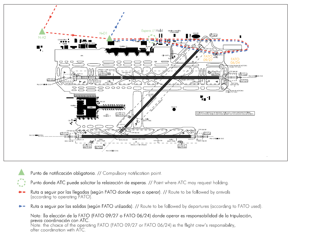
ADDITIONAL INFORMATION
BIRD CONCENTRATION AREAS
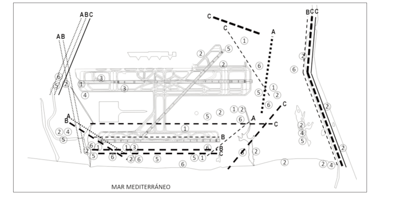
Marked with spots:
Area 1. Concentration of starlings.
Area 2: Concentration of mallard, waterfowl species, great cormorant (October-March) and gulls.
Area 3: Potential place of night feeding of mallard.
Area 4: Concentration of lapwings (October-March).
Area 5: Concentration of swifts and swallows (March-October).
Area 6: Concentration of wood pigeon and rock dove.
Marked with lines:
The thickness of the lines indicates the importance of the movements.
The pattern of the lines indicates the flight height (AGL):
Dotted line: 0-65 ft (0-20 m).
Dashed line: 65-328 ft (20-100 m).
Solid line: >328 ft (>100 m).
Movement A: Movements of wood pigeon and rock dove.
Movement B: Movements of great cormorant (October-March) and other acuatic birds (ducks and seagulls).
Movement C: Movements of seagulls.
AERONAUTICAL CHARTS RELATED TO AN AERODROME
The list of charts related to the aerodrome can be found on the link below:
VISUAL SEGMENT SURFACE (VSS) PENETRATION
The instrument approach procedures affected, can be found below:
IAC 4 VOR RWY 02: direct approach.
IAC 6 RNP Y RWY 02: direct approach.
IAC 10 VOR RWY 06L: direct approach.
IAC 12 RNP Y RWY 06L: LNAV, LNAV/VNAV.
IAC 13 ILS Z RWY 06R: direct approach.
IAC 14 ILS Y RWY 06R: direct approach.
IAC 15 LOC RWY 06R: direct approach.
IAC 16 VOR RWY 06R: direct approach.
IAC 17 RNP Z RWY 06R (LPV only): LPV.
IAC 18 RNP Y RWY 06R: LNAV, LNAV/VNAV.
IAC 22 VOR Z RWY 24L: direct approach.
IAC 23 VOR Y RWY 24L: direct approach.
IAC 25 RNP Y RWY 24L: LNAV, LNAV/VNAV.
IAC 26 ILS Z RWY 24R: direct approach.
IAC 27 ILS Y RWY 24R: direct approach.
IAC 28 LOC RWY 24R: direct approach.
IAC 29 VOR RWY 24R: direct approach.
IAC 30 RNP Z RWY 24R (LPV only): LPV.
IAC 31 RNP Y RWY 24R: LNAV, LNAV/VNAV.