LEMD AD 2 AERODROME DATA
AERODROME LOCATION INDICATORANDNAME
LEMD - MADRID/Adolfo Suárez Madrid-Barajas
AERODROME GEOGRAPHICAL AND ADMINISTRATIVE DATA
ARP | 402820N 0033339W. See AD 2-LEMD ADC. | |
Distance and direction from the city | 13 km NE. | |
Elevation | 609 m / 1998 ft. | |
Geoid undulation | 51 m ± 0.05 m (1). | |
Reference temperature | 34°C. | |
Low average temperature | 5ºC. | |
Magnetic variation | 0º (2020). | |
Annual change | 8.1'E. | |
AD administration | Aena. | |
Address | Aeropuerto de Adolfo Suárez Madrid-Barajas, Avda. de La Hispanidad s/n. 28042 Madrid. | |
TEL | +34-913 936 000 | |
| FAX | +34-913 936 221 |
AFTN | LEMD | |
comaismad@aena.es (COM/AIS); ceopsmad@aena.es (Airport Operations Center). | ||
Approved traffic | IFR. | |
Remarks | (1) For all AD points. Slot requests on the day of operation and outside office hours: Requests for slots on the day of operation and outside office hours (also known as real-time slot requests), should be directed to the Airport Operations Center.
The real-time period starts at 12:00 LT on the working day prior to the date of the flight. |
OPERATIONAL HOURS
Airport | H24. | |
Customs and Immigration | H24. | |
Health and Sanitation | See GEN 1.4. | |
AIS/ARO | H24. (1) | |
Apron Management Service (SDP) | H24. | |
MET briefing | H24. | |
ATS | H24. | |
Fuelling | H24. | |
Handling | H24. | |
Security | H24. | |
De-icing | H24. | |
Remarks | (1) Centralised ARO office geographical area 3.
Centralised AIO Office - International NOTAM Office.
|
HANDLING SERVICES AND FACILITIES FOR CARGO AND MAINTENANCE
Cargo facilities | Up to 10000 kg. Special storage of regulation material. | |
Fuel types | JET A-1. | |
Oil types | No. | |
Refuelling capacity | No limitations. | |
De-Icing facilities | Service provided by handling operator. | |
Hangar space | No. | |
Repair facilities | Yes. | |
Remarks | Ramp agents:
Ramp agents may attend commercial aviation as well as general aviation. General Aviation ramp agents:
NOTE: General Aviation and Business aircraft, see item 20 Local Regulations. |
PASSENGER FACILITIES
Hotels | No. | |
Restaurant | Yes. | |
Transportation | Buses, taxis, hire cars, underground and suburban train. | |
Medical facilities | First aid. Ambulances. | |
Bank/Post Office | Yes. | |
Tourist information | Yes. | |
Remarks | None. |
RESCUE AND FIREFIGHTING SERVICES
Fire category | 10. | |
Rescue equipment | In accordance with the fire category published. | |
Removal of disabled aircraft | Available subject to prior signed declaration by the aircraft operator of inability to remove it with their own means, and releasing the airport manager from liability. (1) Capacities of available equipment:
| |
Remarks | (1) Contact E-mail: ceopsmad@aena.es (Airport Operations Center).
|
RUNWAY SURFACE CONDITION ASSESSMENT AND REPORTING, AND SNOW PLAN
Types of clearing equipment | Pick up vehicles with snowplough blade and de-icer spreader, heavy vehicles with snowplough blade, liquid de-icer spreader, front loader and sweeper trucks. | |
Clearance priorities | Runway, taxiway, apron, service roads, accesses. | |
Use of material for movement area surface treatment | Potassium formate fluid (KFOR). | |
Specially prepared winter runways | Not applicable. | |
Remarks | Period of application of snow plan: 01-NOV to 31-MAR. Runway surface condition assessment and reporting in accordance with the Global Reporting Format (GRF) methodology described in AD 1.2.2. Aerodrome in service during all seasons of the year. |
APRONS, TAXIWAYS AND CHECK LOCATIONS/POSITIONS DATA
Apron | Surface: Concrete and asphalt. Strength:
| |
Taxiways | Width:
Surface: Asphalt and concrete. Strength:
| |
Check locations | Altimeter:
VOR: No. INS: See AD 2-LEMD PDC. | |
Remarks | None.TWY centre line: see INSIGNIA and Data Set. |
SURFACE MOVEMENT GUIDANCE AND CONTROL SYSTEM AND MARKINGS
Taxiing guidance system | Lighted position indicators, NO-ENTRY boards and bars (1), mandatory instructions and information signs LGTD (2), runway-holding positions, intermediate holding positions, stop bars (1), intermediate holding positions lights (1), runway guard lights and stands identification markings. | |
RWY markings | Designators, threshold, displaced threshold RWY 18L, 18R, 32L and 32R, centre line, touchdown zone (except on RWY 14L, 14R, 36L, 36R), side stripe, aiming point (EXC RWY 14L, 14R, 36L, 36R). | |
TWY markings | Centre line, side stripe and reflective markers on edge. | |
Remarks | (1) LED lighting. (2) There are signs with 2 lines of text. |
AERODROME OBSTACLES
Obstacles which penetrate Approach, Take-Off Climb, Conical, Inner Horizontal, Transitional, Inner Transitional and Balked Landing Surfaces established in ICAO Annex 14; and the areas 2A and 3 established in ICAO Annex 15. Those penetrating these surfaces are identified in the CSV file as "Relevante_Relevant = Si/Yes" | See Item 10 and Data Set. | |
Remarks | See AD 2-LEMD AOC. RWY 32R, 32L, 18R and 18L: Not available for take-off. See item 12. |
METEOROLOGICAL INFORMATION PROVIDED
MET office | Barajas EMAe. | |
HR | H24. | |
METAR | Half-hourly. | |
TAF | 30 HR. | |
TREND | Yes. | |
Briefing | In person and by telephone. | |
Flight documentation/Language | Charts and plain language / Spanish/English. | |
Charts | Significant forecasted and wind and temperature in altitude maps. | |
Supplementary equipment | Clouds and lightning image and radar information display. | |
ATS unit served | TWR, APP. | |
Additional information | Madrid OMAe (LEMC): H24
Barajas EMAe: H24
| |
Remarks | Aerodrome climatological summary available. Aerodrome warnings available. Forecasted vertical wind shear warnings are issued in the airport. A meteorological station launches balloons into the aerodrome area, in 4028N 00335W from 1115 to 1130 UTC and from 2315 to 2330 UTC. Aerodrome MET guide available. |
RUNWAY PHYSICAL CHARACTERISTICS
RWY | Direction | DIM (m) | THR PSN | THR ELEV / TDZ ELEV | SWY (m) | CWY (m) | Strip (m) | OFZ | RESA (m) | RWY/SWY SFC / PCN |
|---|---|---|---|---|---|---|---|---|---|---|
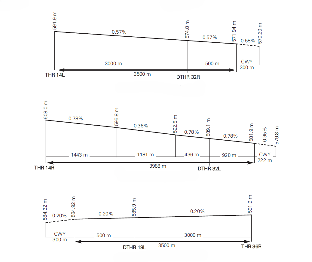
14L (8) (9) | 142.21º GEO 143º MAG | 3500 x 60 | 402941.71N 0033328.33W | THR: 592 m / 1942 ft TDZ: No | No
| 300 x 150 | 3620 x 300 | No | 240 x 150 | ASPH PCN 133/F/A/W/T SWY: No |
32R (1) (7) | 322.22º GEO 323º MAG | 3500 x 60 | 402824.85N 0033210.30W | THR: 574.8 m / 1886 ft TDZ: 579.9 m / 1903 ft | No
| No | 3620 x 300 | Yes | 240 x 150 (6) | ASPH PCN 133/F/A/W/T SWY: No |
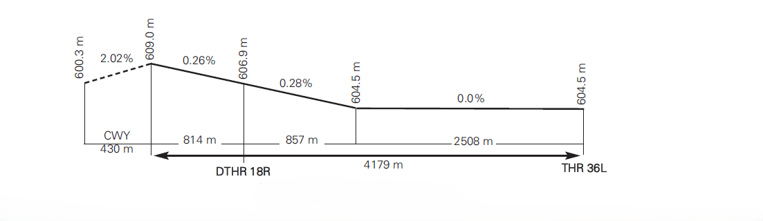
14R (8) (10) | 142.20° GEO 143° MAG | 3988 x 60 | 402905.50N 0033433.64W | THR: 608 m / 1995 ft TDZ: No | No
| 222 x 150 | 4108 x 300 | No | 240 x 150 | ASPH PCN 83/F/A/W/T SWY: No |
32L (2) (7) | 322.21° GEO 323° MAG | 3988 x 60 | 402747.10N 0033314.02W | THR: 589.1 m / 1933 ft TDZ: 594.2 m / 1949 ft | No
| No | 4108 x 300 | Yes | 240 x 150 (6) | ASPH PCN 83/F/A/W/T SWY: No |
18L (3) (7) | 179.76° GEO 180°MAG | 3500 x 60 | 403141.22N 0033333.68W | THR: 585.9 m / 1922 ft TDZ: 587.7 m / 1928 ft | No
| No | 3620 x 300 | Yes | 240 x 150 | ASPH PCN 134/F/A/W/T SWY: No |
36R (8) (11) | 359.76° GEO 360°MAG | 3500 x 60 | 403003.97N 0033333.15W | THR: 592 m / 1942 ft TDZ: No | No
| 300 x 150 | 3620 x 300 | No | 240 x 150 | ASPH PCN 134/F/A/W/T SWY: No |
18R (4) (7) | 179.76° GEO 180° MAG | 4179 x 60 | 403122.40N 0033429.27W | THR: 606.9 m / 1991 ft TDZ: 606.9 m / 1991 ft | No
| No | 4299 x 300 | Yes | 240 x 150 | ASPH PCN 111/F/A/W/T SWY: No |
36L (8) (12) | 359.76° GEO 360° MAG | 4179 x 60 | 402933.32N 0033428.64W | THR: 605 m / 1985 ft TDZ: No | No
| 430 x 150 | 4299 x 300 | No | 240 x 150 | ASPH (5) PCN 111/F/A/W/T SWY: No |
Remarks: (1) THR RWY 32R displaced 500 m. (2) THR RWY 32L displaced 928 m. (3) THR RWY 18L displaced 500 m. (4) THR RWY 18R displaced 814 m. (5) First 273.5 m RWY 36L of hydraulic concrete: PCN 81/R/B/W/U. (6) See item 23 (EMAS). (7) Not available for take-off. (8) Not available for landing. (9) End RWY 14L coordinates: 402812.03N 0033157.29W. (10) End RWY 14R coordinates: 402723.32N 0033249.89W. (11) End RWY 36R coordinates: 403157.44N 0033333.77W. (12) End RWY 36L coordinates: 403148.78N 0033429.41W. | ||||||||||
Profile
DECLARED DISTANCES
RWY | TORA (m) | TODA (m) | ASDA (m) | LDA (m) |
|---|---|---|---|---|
14L | 3500 | 3800 | 3500 | NU |
32R | NU | NU | NU | 3000 |
14R | 3988 | 4210 | 3988 | NU |
32L | NU | NU | NU | 3060 |
18L | NU | NU | NU | 3000 |
36R | 3500 | 3800 | 3500 | NU |
18R | NU | NU | NU | 3365 |
36L | 4179 | 4609 | 4179 | NU |
14L INT K3 | 3280 | 3580 | 3280 | - |
14R INT L1 | 3656 | 3878 | 3656 | - |
36L INT Z4 | 4013 | 4443 | 4013 | - |
36L INT Z6 | 3719 | 4149 | 3719 | - |
36R INT Y2 | 3445 | 3745 | 3445 | - |
36R INT Y3 | 3345 | 3645 | 3345 | - |
Remarks: None. | ||||
APPROACH AND RUNWAY LIGHTING
Runway | 14L | |
Approach | No. | |
PAPI (MEHT) | No. | |
Threshold | No. | |
Touchdown zone | No. | |
Runway centre line | 3500 m: 2600 m white+600 m red and white+300 m red. LIH. Distance between lights: 15 m. (1) | |
Runway edge | 3500 m: 2900 m white + 600 m yellow. LIH. Distance between lights: 60 m. (1) | |
Runway end | Red. (1) | |
Stopway | No. | |
Remarks | (1) LED lighting. |
Runway | 32R | |
Approach | Precision CAT II/III, 900 m. LIH. | |
PAPI (MEHT) | 3° (22.19 m/73 ft). | |
Threshold | Green, with wing bars. (1) | |
Touchdown zone | 900 m white. (1) | |
Runway centre line | 3000 m: 2100 m white+600 m red and white+300 m red. LIH. Distance between lights: 15 m. (1) | |
Runway edge | 3500 m: 500 m red + 2400 m white + 600 m yellow. LIH. Distance between lights: 60 m. (1) | |
Runway end | Red. (1) | |
Stopway | No. | |
Remarks | Rapid exit taxiway indicator lights (K4 and K5). (1) (1) LED lighting. |
Runway | 14R | |
Approach | No. | |
PAPI (MEHT) | No. | |
Threshold | No. | |
Touchdown zone | No. | |
Runway centre line | 3988 m: 3088 m white + 600 m red and white + 300 m red. LIH. Distance between lights: 15 m. (1) | |
Runway edge | 3988 m: 3388 m white + 600 m yellow. LIH. Distance between lights: 60 m. (1) | |
Runway end | Red. (1) | |
Stopway | No. | |
Remarks | (1) LED lighting. |
Runway | 32L | |
Approach | Precision CAT II/III, 900 m. LIH. (1) | |
PAPI (MEHT) | 3° (23.35 m/77 ft). (1) | |
Threshold | Green, with wing bars. (1) | |
Touchdown zone | 900 m white. (1) | |
Runway centre line | 3060 m: 2160 m white + 600 m red and white + 300 m red. LIH. Distance between lights: 15 m. (1) | |
Runway edge | 3988 m: 928 m red + 2460 m white + 600 m yellow. LIH. Distance between lights: 60 m. (1) | |
Runway end | Red. (1) | |
Stopway | No. | |
Remarks | Rapid exit taxiway indicator lights (L2, L3, L4, L5 and L7). (1) LED lighting. |
Runway | 18L | |
Approach | Precision CAT II/III, 900 m. LIH. | |
PAPI (MEHT) | 3° (22.79 m/75 ft). | |
Threshold | Green, with wing bars. | |
Touchdown zone | 900 m white. | |
Runway centre line | 3000 m: 2100 m white+600 m red and white+300 m red. LIH. Distance between lights: 15 m. | |
Runway edge | 3500 m: 500 m red + 2400 m white + 600 m yellow. LIH. Distance between lights: 60 m. | |
Runway end | Red. | |
Stopway | No. | |
Remarks | Rapid exit taxiway indicator lights (Y4 and Y5). |
Runway | 36R | |
Approach | No. | |
PAPI (MEHT) | No. | |
Threshold | No. | |
Touchdown zone | No. | |
Runway centre line | 3500 m: 2600 m white+600 m red and white+300 m red. LIH. Distance between lights: 15 m. | |
Runway edge | 3500 m: 2900 m white + 600 m yellow. LIH. Distance between lights: 60 m. | |
Runway end | Red. | |
Stopway | No. | |
Remarks | None. |
Runway | 18R | |
Approach | Precision CAT II/III, 900 m. LIH | |
PAPI (MEHT) | 3° (20.59 m/68 ft). | |
Threshold | Green, with wing bars. (1) | |
Touchdown zone | 900 m white. (1) | |
Runway centre line | 3365 m: 2465 m white+600 m red and white+300 m red. LIH. Distance between lights: 15 m. (1) | |
Runway edge | 4179 m: 814 m red + 2765 m white + 600 m yellow. LIH. Distance between lights: 60 m. (1) | |
Runway end | Red. (1) | |
Stopway | No. | |
Remarks | Rapid exit taxiway indicator lights (Z7, Z8 and Z10). (1) LED lighting. |
Runway | 36L | |
Approach | No. | |
PAPI (MEHT) | No. | |
Threshold | No. | |
Touchdown zone | No. | |
Runway centre line | 4179 m: 3279 m white + 600 m red and white + 300 m red. LIH. Distance between lights: 15 m. (1) | |
Runway edge | 4179 m: 3579 m white + 600 m yellow. LIH. Distance between lights: 60 m. (1) | |
Runway end | Red. (1) | |
Stopway | No. | |
Remarks | (1) LED lighting. |
OTHER LIGHTING SYSTEMS AND SECONDARY POWER SUPPLY
ABN/IBN | No. | |
WDI | 1 near THR RWY 14R, 1 near THR RWY 14L, 1 near THR RWY 36L, 1 near THR RWY 36R, 1 near THR RWY 32L, 1 near THR RWY 32R, 1 near THR RWY 18R, 1 near THR RWY 18L, LGTD. See AD 2-LEMD ADC 1.1. | |
TWY lighting | Centre line: standard taxiing routes except TWY EF, EH, GATE 15 and GATE 16. (1) | |
Apron lighting | Floodlighting poles. | |
Secondary power supply | Visual aid systems: a) engine generators that provide a MAX switch-over time (light) of 1 SEC for the approach, runway threshold, runway end, runway centre line, touchdown zone and all stop bars systems; b) engine generators that provide a MAX switch-over time (light) of 15 SEC for the rest of the lighting systems, as per Annex 14. | |
Remarks | (1) LED lighting. |
HELICOPTER LANDING AREA
Position | No. | |
Elevation | No. | |
Dimensions, surface, maximum weight, marking | No. | |
Direction | No. | |
Declared distances | No. | |
Lighting | No. | |
Remarks | None. |
AIR TRAFFIC SERVICES AIRSPACE
Designation | CTR MADRID. | |
Lateral limits | 403301.53N 0034658.39W; arc centred on DVOR/DME BRA (402808.9N 0033327.1W), radius 11.4 NM; 402158.81N 0032053.71W; 401544.73N 0031457.24W; 400611.28N 0032929.16W; 401222.89N 0033746.85W; 400809.08N 0034614.61W; 401320.10N 0035258.35W; 401642.37N 0034856.17W; arc centred on MADRID/Getafe AD (401738.6N 0034325.4W), radius 8.0 km; 402038.71N 0034729.48W; arc centred on MADRID/Cuatro Vientos AD (402214.4N 0034706.5W), radius 3.0 km; 402146.76N 0034504.54W; arc centred on MADRID/Getafe AD (401738.6N 0034325.4W), radius 8.0 km; 402154.86N 0034232.04W; 402308.24N 0034112.60W; 403301.53N 0034658.39W. | |
Vertical limits | SFC-1000 ft AGL. | |
Airspace class | D. (1) | |
Unit Language | MADRID APP. ES/EN. | |
Transition altitude | 3962 m / 13000 ft. | |
| Hours of applicability | - |
Remarks | (1) Visual flights only allowed to Spanish military aircraft from/to Ministerio de Defensa facilities. |
Designation | ATZ MADRID/BARAJAS. | |
Lateral limits | Circle radius 8 km centred on ARP. (2) | |
Vertical limits Airspace class | 1000 ft HGT-3000 ft HGT (3)....A. SFC-1000 ft HGT (3)... D. | |
Unit Language | MADRID TWR. ES/EN. | |
Transition altitude | - | |
| Hours of applicability | - |
Remarks | (2) Or the ground visibility, whichever is lower. (3) Or up to the cloud ceiling, whichever is lower. |
AIR TRAFFIC SERVICES COMMUNICATION FACILITIES
Service | Call sign | FREQ | HR | Remarks |
|---|---|---|---|---|
APP | Madrid APP | 118.400 MHz | H24 | APP/I |
118.755 C | H24 | APP/L | ||
124.030 C | H24 | APP/L | ||
128.700 MHz | H24 | APP/H | ||
134.955 C | H24 | APP/L | ||
136.105 C | H24 | APP | ||
127.100 MHz | H24 | INITIAL | ||
127.505 C | H24 | FINAL | ||
124.230 C | H24 | DEP W | ||
131.175 MHz | H24 | DEP E | ||
130.805 C | H24 | BACKUP APP/l | ||
134.030 C | H24 | BACKUP APP/H | ||
TWR | Barajas TWR | 118.080 C | H24 | ARR 18R / DEP 36L |
118.155 C | H24 | ARR 32L / DEP 14R | ||
118.680 C | H24 | ARR 18L / DEP 36R | ||
118.980 C | H24 | ARR 32R / DEP 14L | ||
120.155 C | H24 | BACKUP 1 | ||
120.655 C | H24 | BACKUP 2 | ||
121.500 MHz | H24 | EMERG | ||
243.000 MHz | H24 | EMERG | ||
121.630 C | H24 | GMC E-SOUTH | ||
121.755 C | H24 | GMC E-NORTH | ||
121.980 C | H24 | GMC CENTRAL-SOUTH | ||
123.155 C | H24 | GMC CENTRAL-NORTH | ||
130.080 C | H24 | CLR EAST | ||
130.355 C | H24 | CLR WEST | ||
123.330 C | H24 | DEICING RWY 36L | ||
130.255 C | H24 | DEICING RWY 36R | ||
122.980 C | H24 | FIRE FIGHTING SERVICE | ||
119.500 MHz | H24 | MIL | ||
362.100 MHz | H24 | MIL | ||
SDP | Barajas Apron | 121.705 C | H24 | APRON S-SOUTH |
121.855 C | H24 | APRON S-NORTH | ||
123.005 C | H24 | APRON W-SOUTH | ||
123.255 C | H24 | APRON W-NORTH | ||
123.480 C | H24 | BACKUP | ||
ATIS | Madrid/Barajas Information | 118.255 C | H24 | ARR |
130.855 C | H24 | DEP | ||
D-ATIS | Madrid/Barajas Information | NIL | H24 | Provision of ATIS information via data link. |
RADIO NAVIGATION AND LANDING AIDS
Facility (VAR) | ID | FREQ | HR | Coordinates | DME ELEV | Remarks |
|---|---|---|---|---|---|---|
DVOR (0º) | BRA | 116.450 MHz | H24 | 402808.9N 0033327.1W | - | COV 40 NM AVBL BTN:
|
DME | BRA | CH 111Y | H24 | 402808.6N 0033327.5W | 600 m | COV 40 NM AVBL BTN:
R-349 distance error BTN 6.8 NM and 4.3 NM. |
DVOR (0º) | PDT | 116.950 MHz | H24 | 401510.5N 0032052.9W | - | - |
DME | PDT | CH 116Y | H24 | 401510.4N 0032052.3W | 780 m | - |
DVOR (0º) | RBO | 113.950 MHz | H24 | 405113.9N 0031447.9W | - | R-010 COV:
|
DME | RBO | CH 86Y | H24 | 405114.3N 0031447.4W | 960 m | R-010 COV:
|
DVOR (0º) | SIE | 115.400 MHz | H24 | 410906.1N 0033616.8W | - | COV 10 NM U/S BTN:
R-175 FM 10 NM: Possible signal loss. |
DME | SIE | CH 101X | H24 | 410906.0N 0033617.4W | 1680 m | - |
DVOR (0º) | SSY | 117.850 MHz | H24 | 403247.1N 0033430.7W | - | - |
DME | SSY | CH 125Y | H24 | 403247.1N 0033431.3W | 600 m | - |
DVOR (1º W) | NVS | 114.950 MHz | H24 | 402207.2N 0041457.9W | - | R-279 COV at:
Possible signal loss FM RIDAV. |
DME | NVS | CH 96Y | H24 | 402206.8N 0041457.6W | 780 m |
Possible signal loss FM RIDAV. |
DVOR (1º W) | TLD | 113.200 MHz | H24 | 395810.1N 0042014.6W | - | COV 40 NM AVBL BTN:
R-190 COV:
|
DME | TLD | CH 79X | H24 | 395810.0N 0042014.0W | 600 m | COV 40 NM AVBL BTN:
R-190 COV:
|
DVOR (0º) | CNR | 117.300 MHz | H24 | 403845.5N 0034409.0W | - | - |
DME | CNR | CH 120X | H24 | 403845.8N 0034408.5W | 810 m | - |
VOR (1ºW) | NEA | 116.750 MHz | H24 | 420139.4N 0040632.9W | - | COV 40 NM AVBL BTN:
R-065 at FL090: Possible signal oscillations greater than ±2º BTN 0 & 10 NM. R-185 at FL100: Possible signal oscillations greater than ±2º BTN 0 & 5 NM. R-248 at FL110: Possible signal oscillations greater than ±2º BTN 0 & 10 NM. |
DME | NEA | CH 114Y | H24 | 420139.2N 0040633.1W | 900 m | COV 40 NM AVBL BTN:
|
DVOR (0º) | BAN | 112.800 MHz | H24 | 411924.8N 0023747.2W | - | COV 40 NM AVBL BTN:
|
DME | BAN | CH 75X | H24 | 411925.2N 0023747.7W | 1140 m | COV 40 NM AVBL BTN:
|
DVOR (0º) | CJN | 115.600 MHz | H24 | 402219.1N 0023240.6W | - | R-069 COV at:
|
DME | CJN | CH 103X | H24 | 402218.6N 0023240.8W | 1080 m | R-069 COV at:
|
LOC 32L (0º) ILS CAT III | MAA | 109.900 MHz | H24 | 402912.1N 0033440.4W | - | 323° MAG / 258 m FM THR 14R; COV 17 NM AVBL at 5000 ft AMSL or ABV. COV 25 NM AVBL at 5500 ft AMSL or ABV. |
GP 32L | 333.800 MHz | H24 | 402757.2N 0033317.3W | - | 3°; RDH 16.6 m; at 294 m FM THR 32L & 130 m FM RCL to the right in the direction of APCH. | |
ILS/DME 32L | MAA | CH 36X | H24 | 402757.2N 0033317.3W | 594 m | REF DME DTHR 32L. |
LOC 18L (0º) ILS CAT III | IML | 111.500 MHz | H24 | 402954.2N 0033333.1W | - | 180º MAG / 302 m FM THR 36R.
|
GP 18L | 332.900 MHz | H24 | 403131.5N 0033329.0W | - | 3º; RDH 16.3 m; at 299 m FM THR 18L & 110 m FM RCL to the left in the direction of APCH. | |
ILS/DME 18L | IML | CH 52X | H24 | 403131.5N 0033329.6W | 591 m | REF DME DTHR 18L. |
LOC 18R (0º) ILS CAT III | IMR | 110.700 MHz | H24 | 402922.7N 0033428.6W | - | 180°MAG / 327 m FM THR 36L.
|
GP 18R | 330.200 MHz | H24 | 403111.9N 0033423.3W | - | 3°, RDH 16.4 m; at 326 m FM THR 18R & 140 m FM RCL to the left in the direction of APCH. | |
ILS/DME 18R | IMR | CH 44X | H24 | 403111.8N 0033423.9W | 612 m | REF DME DTHR 18R. |
LOC 32R (0º) ILS CAT III | MBB | 109.100 MHz | H24 | 402949.4N 0033336.2W | - | 323º MAG / 302 m FM THR 14L. COV 17 NM AVBL at 5500 ft AMSL or ABV. COV 25 NM AVBL at 5500 ft AMSL or ABV. |
GP 32R | 331.400 MHz | H24 | 402834.5N 0033213.7W | - | 3º, RDH 16.5 m; at 284 m FM THR 32R & 120 m FM RCL to the right in the direction of APCH. | |
ILS/DME 32R | MBB | CH 28X | H24 | 402834.2N 0033214.2W | 582 m | REF DME DTHR 32R. COV 17 NM AVBL BTN 35º to the left and 31º to the right of RCL at 5500 ft AMSL or ABV. |
Local aerodrome regulations
Operating restrictions adopted as a result of environmental restrictions must be complied unless the airport management considers suspending them due to causes of force majeure which seriously affect passengers. This suspension must be, in any event, temporary and exceptional and the Airport will notify those involved.
ILS CATEGORY II AND III OPERATIONS
RWY 18L/18R and 32L/32R, subject to service availability of the appropriate approach and landing aids, are suitable for the carrying out of CAT II and III operations by those air operators whose operating minima have been approved by the aeronautical civil authority.
RESTRICTIONS TO OPERATIONS
Aerodrome closed to aircraft without radio communication and helicopters.
Aerodrome closed to piston-engined aircraft.
Aerodrome closed to training operations.
All aircraft wishing to operate at the airport must have engaged a handling agent.
General and Business Aviation Aircraft :
All aircraft with MTOW less than 10000 Kg and/or fewer than 20 seats must have engaged the services of either of these two General and Business Aviation managers authorized by the airport:
AVIAVIP FBO MADRID
TEL H24: +34 629 361 111
E-mail: lemd@aviavip.com
UNITED AVIATION FBO
TEL H24: +34-913 936 775
E-mail 1: ops.mad@unitedaviation.es
E-mail 2: fbo.mad@unitedaviation.es
In every slot message or request for General Aviation and Business flights wishing to operate at the airport, the following must be included:
Flight Handling agent,
General and Business Aviation manager if engaged.
Any aircaraft whose MTOW is more than 10000 kg and/or has 20 seats or more will not be considered General or Business Aviation.
POINT OF ENTRY (PEV) FOR PASSENGERS WITH PET ANIMALS FROM THIRD COUNTRIES
To guarantee compliance with the Regulation (EU) No 576/2013 of the European Parliament and of the Council of 12 June 2013 on the non-commercial movement of pet animals and repealing Regulation (EC) No 998/2003, any Air Carrier wishing to operate at the Airport and transporting in the cabin, as a part of passenger hand baggage, the animals (pets) set out in part A of Annex I to the mentioned Regulation (dogs, cats and ferrets), must have engaged a handling agent who to be responsible for handling the same in those cases where, during the checks undertaken by the Resguardo Fiscal of the Guardia Civil or Customs Personnel of the Passenger Terminal of Adolfo Suárez Madrid-Barajas Airport, some breach of the health requirements established in the cited regulations is detected which prompts the animal's rejection at the border.
The handling of an animal rejected at the border shall include, at least, its removal to the facilities of the Border Inspection Service at the cargo terminal in question, its subsistence, veterinary care and animal welfare, and even its return to the point of origin within the periods established by the health authorities.
FLIGHT PLAN
The operations office at Adolfo Suárez Madrid-Barajas shall not accept flights with origin or destination Adolfo Suárez Madrid-Barajas AD, with an EOBT or ETA in the flight plan does not match with the airport slot previously allocated (see GEN 1.2, item 3).
For General Aviation and Business flights wishing to operate at the airport, the following information must be included in item 18 "Other information":
Flight Handling agent,
General and Business Aviation manager if engaged.
NIGHT OPERATING RESTRICTIONS DUE TO NOISE QUOTA
OPERATING RESTRICTIONS
AIRCRAFT WITH CR4 OR HIGHER
Take-off and landing operations of aircraft rated as CR-4 or higher are prohibited at night time (23:00 to 6:59 LT).
MARGINALLY COMPLIANT AIRCRAFT
(subsonic civil jet aircraft in compliance with the certification limit values under Volume I, Second part, Chapter 3 of Annex 16 of the Convention on International Civil Aviation by an accumulated margin not higher than 5 EPNdB).
From 28 September 2012, operation with marginally compliant aircraft is prohibited both by day and by night.
NOISE QUOTA AIRCRAFT CLASSIFICATION (CR)
Noise quota (CR) is defined for each aircraft, distinguishing between departure and arrival operations, in accordance with the EPNdB certificate (Effective Perceived Noise measured in decibels) related to the following table:
EPNdB | NOISE QUOTA (CR) |
|---|---|
more than 101.9 | CR-16 |
99-101.9 | CR-8 |
96-98.9 | CR-4 |
93-95.9 | CR-2 |
90-92.9 | CR-1 |
less than 90 | CR-0.5 |
Propeller aircraft certified in accordance with chapters 6 and 10 of ICAO Annex 16, and propeller or jet aircraft certified according to chapters 3 and 5, with noise levels less than 87 EPNdB, will be considered to have a noise quota of zero (CR-0).
The EPNdB is defined in accordance with the following criteria:
In take-off operations for aircraft certified according to chapters 3, 4 and 5 of ICAO Annex 16, the average value between the take-off and sideline certified noise levels, measured in EPNdB, at its maximum certified take-off weight.
In arrival operations for aircraft certified according to chapters 3, 4 and 5 of ICAO Annex 16, the certified approach noise level measured in EPNdB at its maximum certificated landing weight, minus 9 EPNdB.
EXCEPTIONS Exceptionally, the airport directorate may authorise landing or take-off operations of aircraft with noise quotas (CR) equal to or higher than CR-4 when:
The operation takes place within 30 minutes after or before the time limits expected, as long as this is due to a delay caused by the programmed operation.
The operation is justified for safety reasons, or is necessary for assisting the transportation of urgent humanitarian aid, and other operations necessary due to operational alterations arising from meteorological conditions, industrial actions or other exceptional occurrences.
PREFERENTIAL CONFIGURATIONS
Between 0700 and 2300 LT:
Preferential: North Configuration.
Arrivals: 32L/32R.
Departures: 36L/36R.
Non preferential: South Configuration.
Arrivals: 18L/18R.
Departures: 14L/14R.
Between 2300 and 0700 LT:
Preferential: North Configuration.
Arrivals: 32R.
Departures: 36L.
Non preferential: South Configuration.
Arrivals: 18L.
Departures: 14L.
The preferential configurations will be maintained until wind components are produced, including 10 kt gusts of tailwind and/or 20 kt crosswind, the change may be considered from 7 kt of tailwind, except for safety reasons, the inoperativeness of any runway or air navigation aid disabling any of the approved standard instrument departures and arrivals, or when one or more of the following meteorological conditions prevail or are forecasted:
Runway surface conditions adversely affected and/or with breaking action below good,
Cloud ceiling lower than 500 ft above aerodrome elevation,
Visibility less than 1.9 km (1 NM),
Wind shear notified or forecasted, or storms on approach or departure,
Other meteorological phenomena that may prevent it.
In such cases, ATC shall notify the Airport, which will confirm whether works are in progress on the surface or facilities of non-preferential runways.
In south configuration, for the purpose of determining the preferential runways, during the nights from Friday to Saturday and from Saturday to Sunday, the night period will be considered from 2300 to 0900 LT, whenever the operational circumstances permit so. Daytime SIDs must be used in their appropriate schedules.
MADRID ACC will clear approaching aircraft taking into account TMA MADRID geographical entry criteria (arrivals to RWY 32R/18L from the East and to RWY 32L/18R from the West) except when it is necessary to assign a different runway for arrivals due to safety reasons or to obtain a continuous traffic flow.
ATIS messages shall broadcast information on the configuration in use of runways.
MINIMUM RUNWAY OCCUPANCY TIME
ARRIVALS
To minimize the runway occupancy time and the possibility of “go-around”, pilots are reminded:
The following RET should be used, unless otherwise instructed by ATC. Otherwise, it is critical to report it to ATC in the initial contact with APP or the initial contact with TWR, as soon as possible:
WAKE | RWY 32L | RWY 32R | RWY 18L | RWY 18R | ||||
|---|---|---|---|---|---|---|---|---|
LEFT | RIGHT | LEFT | RIGHT | LEFT | RIGHT | LEFT | RIGHT | |
SUPER | - | L2 (2) | K4 | ... | ... | Y4 | Z7 | Z8 |
HEAVY | L3 (1) | |||||||
MEDIUM (JET) | L5 (1) | L4 (2) | K5 | Y5 | Z10 | |||
MEDIUM (PROP) + | L7 (3) | |||||||
(1) And turn left on TWY A, hold short of first TWY G intersection.
(2) And hold short of TWY A.
(3) And follow ATC instructions.
To vacate runway expeditiously at the fastest speed commensurate with safety.
TWR may indicate compulsory departures following those indicated in the table.
To adjust taxi speed after touchdown when it is evident that the aircraft will miss the planned RET, avoiding low speeds on the runway.
The lights of L7 will automatically turn off when RVR is less than 800 m.
Vacating via K3, L1, LA, LE, Y3 and Z4 is prohibited, except in exceptional situations and with TWR clearance, as it generates ILS signal interference.
Vacating via TWY K1, K2, LC, LB, Y1, Y2, Z1, Z2, Z3 and Z6 is not lit and is prohibited, except in exceptional situations, as it generates ILS signal distortion.
The following RET are available:
RWY | ACFT | DIST THR-RET (M) | RET |
|---|---|---|---|
32L | all | 1518 | L7 |
32L | all | 1852 | L5 |
32L | all | 1815 | L4 |
32L | all | 2128 | L2 |
32L | all | 2373 | L3 |
32R | all | 1800 | K5 |
32R | all | 2400 | K4 |
18R | all | 1926 | Z10 |
18R | all | 2352 | Z8 |
18R | all | 2352 | Z7 |
18L | all | 1800 | Y5 |
18L | all | 2400 | Y4 |
DEPARTURES
Pilots should be ready for departure when reaching the runway-holding position. On receipt of line-up clearance pilots should ensure that they are able to taxi and line-up on the runway as soon as the preceding aircraft has commenced its take-off run.
Pilots who require additional separations (due to wake turbulence or other reason), shall notify ATC as soon as possible and before crossing the runway-holding position. Pilots should be able to commence the take-off run immediately when takeoff Clearance is issued.
Pilots unable to comply with this requirement shall notify ATC as soon as possible and await instructions. When appropriate, ATC could cancel the clearance and instruct the aircraft to vacate runway.
TWR-APP FREQUENCY CHANGE
IFR traffic: Unless otherwise instructed by Barajas TWR, after take-off and on reaching 1000 ft AGL, traffic will contact on the corresponding frequency of Madrid APP according to take-off runway, except in case of execution of ODP LEMD1N or LEMD1W contingency SID, in which case the traffic shall remain on the Barajas TWR frequency and await instructions. In the event that contact cannot be established with Madrid APP, contact Barajas TWR again.
ATC PROCEDURES
Although the runway is temporarily occupied by aircraft landing and taking off, landing clearance may be issued to an arriving aircraft if the controller is satisfied that, at the time the aircraft crosses the threshold of the runway in use, there will be sufficient separation between said aircraft and the preceding aircraft.
When issuing a “Landing Clearance based on Anticipated Separation”, ATC shall issue clearance to the succeeding aircraft with the following instructions: “...(Call sign) BEHIND LANDING/DEPARTING (aircraft type) CLEARED TO LAND RUNWAY (number)”.
This procedure may be used between sunrise and sunset and without detriment to the requirements established in the Reglamento de la Circulación Aérea (Book Four, Chapter 10, paragraph 4.10.2.4) refering to the use of conditional phrases for movements affecting the runway or runways in operation.
TAKE-OFF FROM INTERSECTION
Pilots requesting or accepting to take off from the intersection, shall inform ATC accordingly on initial contact with GMC. When requested by the pilot, ATC will consider that the take-off distance from the proposed intersection is the minimum required for that particular flight.
Standard TAXIING PROCEDURES
START-UP OF ENGINES/TURBINES
The process of priority ATC clearance at the airport is via data link, as described in Section 1.1 ATC CLEARANCE REQUEST AND START-UP VIA DATA LINK. If DCL is unavailable, the ACFT must be fully ready for start before the crew calls on the corresponding frequency: 130.355 MHz if proceeding via SIE, ZMR, BARDI, CCS or VTB, and 130.080 MHz if via RBO, PINAR or NANDO.
The pilot shall make a single call to Madrid Clearances on the corresponding frequency, within the interval to -5 minutes of its TOBT (Target Off-Blocks Time) until +5 minutes of its TSAT (Target Start Up-Approval Time). On requesting start-up, they will notify the complete call sign of the flight, type of ACFT and series, the stand occupied and theATIS message received.
If possible, in compliance with A-CDM procedures, Madrid Clearances will approval for start-up together with the ATC authoritation. Otherwise will be entered in the A-CDM system, reporting the TSAT of the flight. The entry of the start-up request into the system is equivalent to requesting the ready message (REA), for flights regulated with CTOT (calculated take-off time). To avoid saturating the frequency pilots shall refrain from making successive calls before receiving the call Madrid Clearances to approve their start-up in accordance with the TSAT.
Should the A-CDM parameters not be fulfilled, the start-up request will not be entered in that system, and the crew should contact their flight dispatcher to correct the A-CDM parameters.
To avoid overloading the frequency, Madrid Clearances will not facilitate about non compliances with the A-CDM process. If the TOBT can not be met at any moment, it should be updated immediately by the airline or handling agent.
If the start-up request has not been received within 5 minutes after TSAT flight will miss its TSAT and a new updated TOBT will be required, for the flight to be sequenced again and the system to assign it a new TSAT. The TOBT and/or EOBT can only be updated by the airline or its ground agent, so that pilots shall refrain from making requests of this nature to ATC.
After the approval for start-up, Madrid Clearances will instruct the ACFT to contact the Apron Management Service (SDP) on the corresponding frequency. The SDP shall be responsible for issuing instructions and taxiing. The departure of ACFT parked at remote stands will be managed directly by ATC; once start-up has been approved, Madrid Clearances will give instructions for them to taxiing clearance on the corresponding ATC frequency.
At stands with towed exit manoeuvres, the push-back request shall be made no later than 5 minutes after receiving start-up clearance.
At stands with autonomous exit manoeuvres, the taxiing request shall be made no later than 10 minutes after receiving start-up clearance.
If the ACFT requires additional time, this shall be requested at the time of start-up.
If no explanatory communication is provided by the flight crew, ATC may revoke the start-up clearance, resulting in a reset of A-CDM procedures. In such cases, the flight shall update its TOBT and await a new TSAT.
In all the stands in contact with the terminal building, it is prohibited to start engines above idling until the ACFT is lined up on the taxiway.
Using reverse thrust to leave the stands i is prohibited without express authority.
ATC AUTHORIZATION REQUEST AND START-UP VIA DATA LINK
Data Link (DCL) departure procedures are applied at MADRID/Adolfo Suárez Madrid-Barajas airport in the provision of ATC clearance and start-up services. For more information on the DCL service, see AIP ENR 1.5, section 3. FLIGHTS, ATC Clearance and start-up via data link (DCL).
In case of discrepancies, voice communications will always prevail over data link.
The pilot may request the ATC clearance by DCL in accordance with the start up of engines/turbines procedures (see AD 2, item 20, 1) with a maximum of 30 minutes before the TOBT (CDM mode) or EOBT (without CDM).
The pilot must request ATC and S/U clearance together via RCD. The RCD message (Departure Clearance Request) must contain the following information:
Aircraft callsign in accordance with the filed flight plan (FPL).
Aerodrome of origin.
Aircraft stand.
Destination aerodrome.
Letter corresponding to the ATIS information received.
ICAO aircraft type designator.
Any free text sent via the RCD by the pilot will not be considered by the ATC. Special requests, for instance -icing, will always be made via voice communications.
The pilot will receive a message acceptance “RCD RECEIVED” or cancellation "RCD REJECTED".
When communicating approval, Madrid Clearances will issue a CLD message with the following fields:
Aircraft callsign.
Destination aerodrome.
Assigned runway for departure.
Take-off procedure (SID). Note: The initial altitude will correspond to the published SID.
SSR code mode A (SQUAWK).
ADT (Approved Departure Time). Note: ADT = CTOT of the flight, if applicable.
Next frequency.
Current ATIS information letter.
Additional information, which will include start-up clearance or instructions to request it in case of failure to comply with the startup approval parameters indicated in AD 2, Item 20, 1.
Depending on the moment when the RCD is sent, either ATC clearance or ATC Clearance and Start-Up Approval may be sent.
CDM MODE
From TOBT-30 to TOBT-5, only ATC Clearance will be sent, and pilots are reminded to call when they are ready, in accordance with their TOBT.
From TSAT-5 to TSAT+5 they will receive ATC Clearance and Start-Up Approval.
From TOBT-5 but before TSAT-5, ATC Clearance will be sent and pilots shall monitor the frequency stated in the DCL message until they can be conceded Start-Up Approval. In the case of flights with CTOT, an REA message may be sent, and the aircraft will be informed of this in the text of the CLD message.
NON-CDM MODE
Between EOBT-30 and EOBT+15, the RCD will be accepted and ATC Clearance will be sent in all cases, reminding the crew to call when they are ready and in accordance with their EOBT/CTOT.
When a CLD message is sent in the valid range of TOBT and TSAT, ATC clearance and start-up will be received. If not ready for start-up, the pilot must not accept the authorization and will either send a new message or contact via voice communications to the controller when ready.
When an FSM message of the type “REVERT TO VOICE PROCEDURES” is received, communication via data link will be terminated and must be reverted to voice procedures.
When a CLD message is received, the pilot:
If any inconsistencies in the received message are detected, the pilot must revert to voice procedures and request a new authorization.
If the pilot considers the authorization CLD message to be correct, he/she must respond via data link with a CDA message (Departure Clearance Echoback).
If a CDA message is not received by the pilot within the waiting time, or a CDA that is inconsistent with the previous CLD message is received, communication via data link will be terminated and a “CDA REJECTED” message will be received in the FMS.
When the correct CDA message is received, the ATC system will send the aircraft a “CLEARANCE CONFIRMED” message in the FMS and will terminate the communication via data link.
The push-back request must be made to the Apron Management Service (SDP) on the appropriate frequency. The SDP will be responsible for issuing instructions and approval for push-back and/or taxiing. The push-back or taxiing request should commence within 5 minutes of reception of start-up confirmation. In the case of remote stands, the time allowed between start-up and the request for taxiing shall be extended to 10 minutes.
Should the ACFT need more time, this should be requested with the start-up, and if there is no communication justifying this from the crew, start-up may be revoked, with the corresponding restart of the A-CDM procedures.
Ground Movement
All surface movements of aircraft, towed aircraft, personnel and vehicles on the manoeuvring area are subject to previous ATC clearance.
Barajas Ground Movement Control (GMC) is responsible for:
The control of every aircraft, personnel and vehicles movements on the manoeuvring area except for the runway or runways in use.
Issuing approval for towed push-back and taxiing instructions to aircraft at PRKG 7 to 9 of T-123 apron.
Reporting the stands assigned to the aircraft by Centro de Gestión Aeroportuaria (CGA) at PRKG 20 to 26 of T-123 apron.
Guidance via “FOLLOW ME” vehicles shall only be provided for access to stands from Sunset to Sunrise in PRKG 10 to 13 of Ramp 1, PRKG 14 to 17 of Ramp 2, PRKG 30 of Ramp 4 and in the case of PRKG 40 to 45 of Ramp 4 when the pavement is wet.
Guidance service shall be provided in exceptional cases and at the request of the pilot in command of the aircraft.
Aircraft vacating runway via a rapid exit taxiway will always have priority over the rest of aircraft, which must give way to them using the intermediate holding positions.
Aprons of this airport have an Apron Management Service (SDP) in charge of:
The management of all aircraft movements.
Issuing instructions for towed push-backs and/or taxiing.
Notifying the aircraft of the stand assigned by Centro de Gestión Aeroportuaria (CGA).
Aircraft shall approach the runway-holding and intermediate positions as closely as possible, as no free space is guaranteed behind them (see AD 1.1). It is the aircraft commander's responsibility to remain watchful of the surroundings and take measures to avoid collisions with other aircraft, as well as to inform ATC when any clearance cannot be carried out. If there is any doubt as to whether an aircraft positioned at a runway-holding position or an intermediate holding position may be overtaken safely, the taxiing aircraft shall halt, report ATC and request alternate instructions.
Aircraft accessing Apron T4 shall call on the corresponding SDP APRON W-SOUTH 123.005 MHz or APRON W-NORTH 123.255 MHz frequency without the need for ATC instructions.
The crew shall change frequency upon reaching the ATC-SDP transfer point (see AD2-LEMD PDC 2 and GMC 1/GMC).
In the absence of instructions from SDP to proceed, aircraft shall stop at the taxiing instruction boundary obtained from ATC without encroaching upon TWY X.
Similarly, aircraft exiting Apron T4 shall call on GMC CENTRAL-NORTH 123.155 MHz or GMC CENTRAL SOUTH 121.980 MHz frequencies without the need for SDP instructions.
The crew shall change frequency on reaching the SDP-ATC transfer point (see AD-2 LEMD PDC 2 and GMC 1/GMC 2).
In the absence of instructions from ATC to proceed, they shall stop at the clearance boundary obtained from SDP without encroaching upon TWY M or MZ as appropriate.
This procedure is suspended when LVP is active, when the airport’s Winter Plan is active, when training simulations are ongoing, and when the frequencies normally used by any sector involved in the procedure are not available, and the aircraft must wait for ATC or SDP instructions to contact the next frequency.
Push-back manoeuvring and taxiing.
Push-back manoeuvres shall be accomplished according to AD 2-LEMD PDC 1.3/4/5/6/7/8 or AD 2-LEMD PDC 2.3/4/5/6 procedures, unless the Apron Management Service (SDP) advise differently.
Unless GMC or the Apron Management Service (SDP) indicate another route, aircraft will taxi along the appropriate STANDARD TAXIING ROUTE shown below.
ATC clearances and instructions must be read back. The instructions from the Apron Management Service (SDP) must be also read back.
In all stands with autonomous exits, the exits manoeuvre will be carried out at the minimum power required to initiate taxiing.
From 2300 to 0700 LT, movements in Ramps 5 and 6 are prohibited. It will only be permitted, in the PRKG 75 to 140, to use the equipment necessary for the tasks associated with the maintenance of the aircraft and, if required, when an aircraft needs to be dragged outside the restricted area, this shall be performed by means of an electric tractor, complying with the following:
Entry to PRKG 75 and 80 to 140: All aircraft shall stop at TWY A4 (in north configuration) or at TWY M4 (in south configuration) and, from there, wait with their engine switched off to be towed to the assigned stand. Only electric engine towing tractors are permitted.
Exit from PRKG 75 and 80 to 140: aircraft shall be towed with their engines switched off until being aligned with TWY M4 (in north configuration) or TWY A4 (in south configuration). Only electric engine towing tractors are permitted.
The use of APU is prohibited for all types of aircraft during taxiing operation.
If the pilot cannot keep oral communication via headphones or radio with the coordinator or the tractor driver during the push-back manoeuvre, he/she will immediately notify to the Apron Management Service.
Taxiing restrictions.
GENERAL
Aircraft classification according to chapter 1 of annex 14 ICAO:
Code letter F: 65 m or above wingspan, and below 80 m.
Code letter E: 52 m or above wingspan, and below 65 m.
Code letter D: 36 m or above wingspan, and below 52 m.
Code letter C: 24 m or above wingspan, and below 36 m.
Code letter B or below: Below 24 m wingspan.
TAXIING
Restrictions to taxiways and access to apron gates due to maximum wingspan:
TWY limited to usage by code letter B aircraft.
TWY CA, CB, C1 from PRKG 117, and C9.
Usage restrictions:
No restrictions.
TWY limited to usage by code letter C aircraft.
TWY C1 from M1 until PRKG 116, C2 from M2 until PRKG 110, DI2, I12, GATE 7, J5, J6, JI5, JI6, W5, W6, WI6, WA, WN1 and WN2.
Usage restrictions:
TWY DI2: exit only for PRKG 372, 374 and 376.
TWY limited to usage by code letter D aircraft:
TWY C2 between A2 and M2, C11, DI3, DI4, section of I9 between PRKG 13 and GATE 4, I10 to I11, GATE 4 to GATE 6.
Usage restrictions:
GATE 6, TWY C11, I11, connection curves between TWY I10 and I12: maximum wingspan 38 m.
TWY DI3, DI4: code letter C if TWY D3, D4 occupied by code letter E aircraft.
B764 aircraft shall oversteer during all turns.
TWY limited to usage by code letter E aircraft:
TWY A1 to A17, AM1, AM2, AZ2 to AZ6, C1 between A1 and M1, C3 to C7, D1 to D5, E1 to E4, EB1 to EB8, EC2 to EC9, EF, EH, F1 to F4, G1 to G6, G14, GATE 1 to GATE 3, GATE 14, GATE 15, GATE 16, H2 to H4, I7 to I8, I9 section between GATE 3 and PRKG 13, J2 to J4, KA8, L1, L3, L5, L7, LA, LB, LC, LD, M1 to M17, M27 to M31, MZ3 to MZ7, NY11 to NY13, Q3, R1 to R8, S2 to S4, U2 to U4, W1 to W4, WN3, X2 to X6, Z2, Z4, Z6, Z8, Z10, Z12, ZW1 to ZW5.
Usage restrictions:
Code letter F aircraft and A346, A35K, B779, B77W and B764 must oversteer at all turns.
TWY D3, D4: code letter D if TWY DI3, DI4 occupied by a code letter D aircraft.
TWY EB1: maximum wingspan of 58 m if TWY EC1 occupied by code letter F aircraft with a wingspan greater than 73.3 m (A380).
TWY WN3: code letter C if PRKG 400 occupied.
TWY X2: code letter C if PRKG 448 occupied by aircraft with a length greater than 64 metres.
TWY Z2, Z4: cannot be used simultaneously by two code letter E aircraft.
TWY Z4: cannot be used by any other aircraft of code letter E or above if TWY Z2 is occupied by a code letter F aircraft and vice versa.
Aircraft of code letter F may not use runway-holding positions LC and LD for RWY 14R.
TWY limited to usage by code letter F aircraft:
TWY A18 to A34, AY, AM3, AM4, B1 to B13, BN1, BN3, BY11 to BY13, EA1, EA2, EA5 to EA7, EC2 up to PRKG 628, G11 to G13, GATE 11, K1 to K5, K7, K8, KA1 to KA7, KB1 to KB2, KC1 to KC3, L2, L4, L42, LE, M18 to M25, M27 up to access to PRKG 627, M32 to M34, MC, MD, ME1, ME2, N1 to N13, Y1 to Y5, Y7, Z1, Z3, Z7.
Usage restrictions:
TWY AM3: maximum wingspan of 78 m (A380 not allowed) if TWY A27 occupied by code letter F aircraft with a wingspan greater than 78 m (A380) and vice versa.
TWY EC1: maximum wingspan of 78 m (A380 not allowed) if TWY EB1 occupied by code letter E aircraft with a wingspan greater than 58 m.
TWY M27 up to access to PRKG 627: maximum wingspan of 78 m (A380 not allowed) if TWY A27 occupied by code letter F aircraft with a wingspan greater than 78 m (A380).
Restrictions to stands:
Routes from/to PRKG 40, 165, 259 and 263 on T123 apron for B748 aircraft:
NORTH CONFIGURATION:
Arrival RWY 32L/32R: standard route.
Departure RWY 36L: standard route until M15, ..., MZ3, R1, Z4 or standard route until M14, ..., M20, B2, holding point Z1.
Departure RWY 36R: standard route until M15, ..., M20, B2, ..., B13, holding point Y3.
SOUTH CONFIGURATION:
Arrival RWY 18R: standard route.
Arrival RWY 18L: follow ATC instructions via N, ..., N2, M21, ..., standard route.
Departure RWY 14R: standard route until holding point LA or continue A12, ..., A19, ME2 to holding point LE.
Departure RWY 14L: standard route.
Routes from/to PRKG 165, 259 and 263 on T123 apron for A124 aircraft:
These routes shall also be followed when LVP procedures are active.
NORTH CONFIGURATION:
Arrival RWY 32L: L4 or L2, TWY A until A11, standard route.
Arrival RWY 32R: standard route.
Departure RWY 36L:
PRKG 165: A5, A6, A7, G1, M8…M20, B2, holding point Z1.
PRKG 259 and PRKG 263: E2, E1, A7, G1, M8…M20, B2, holding point Z1.
Departure RWY 36R: same route as 36L until M20, B2, ..., B13, holding point Y3.
SOUTH CONFIGURATION:
Arrival RWY 18R: Z7, G13, N5, ..., N2, M21, …, M8, G1, A7, A6 to PRKG 165 or G1, F2, F3 to PRKG 259 and 263.
Arrival RWY 18L: follow ATC instructions via N, M21, ..., M8, G1, A7, A6 to PRKG 165 or G1, F2, F3 to PRKG 259 and 263.
Departure RWY 14R: standard route until A12, A13, …, A19, ME2 to holding point LE.
Departure RWY 14L: standard route.
Routes from/to PRKG 165, 259 and 263 on T123 apron for A388 aircraft:
These routes shall also be followed when LVP procedures are active.
NORTH CONFIGURATION:
Arrival RWY 32L: L4 or L2, TWY A until A11, standard route.
Arrival RWY 32R: standard route.
Departure RWY 36L:
PRKG 165: A5, A6…A14, AZ2, M17…M20, B2, holding point Z1.
PRKG 259 and PRKG 263: E2, E1, A7…A14, AZ2, M17…M20, B2, holding point Z1.
Departure RWY 36R: same route as 36L until M20, B2, ..., B13, holding point Y3.
SOUTH CONFIGURATION:
Arrival RWY 18R: Z7, G13, N5, ..., N2, M21, …, M17, AZ2, A14, …, A6 to PRKG 165 or A8, F2, F3 to PRKG 259 and 263.
Arrival RWY 18L: follow ATC instructions via N, M21, ..., M17, AZ2, A14, …, A6 to PRKG 165 or A8, F2, F3 to PRKG 259 and 263.
Departure RWY 14R: standard route until A12, A13, …, A19, ME2 to holding point LE.
Departure RWY 14L: standard route.
STANDARD TAXIING ROUTES
NORTH CONFIGURATION
ENTRY
From RWY 32L to T-123:
Standard route: L7, L5 or L3, TWY A towards A11.
Ramp 7
PRKG 178 to 227: Standard route, A10 (transfer point A10-2), …, A6, C7.
PRKG 243 to 249: Standard route, A10 (transfer point A10-2), …, A6, C9.
PRKG 258 to 264: Standard route, A10 (transfer point A10-2), …, A8, F2, F3.
Ramp 6
PRKG 75: Standard route, A10 (transfer point A10-2), …, A4, C4, I6.
PRKG 80 to 85: Standard route, A10 (transfer point A10-2), …, A3, C3.
PRKG 90 to 110: Standard route, A10 (transfer point A10-2), …, A2, C2.
PRKG 111 to 126: Standard route, A10 (transfer point A10-2), …, A1, C1.
PRKG 130 to 135: Standard route, A10 (transfer point A10-2), …, A1, C1, CA.
PRKG 136 to 140: Standard route, A10 (transfer point A10-2), …, A1, C1, CB.
PRKG 145 to 148: Standard route, A10 (transfer point A10-2), …, A1.
Ramp 5
PRKG 50 to 67: Standard route, A10 (transfer point A10-2), …, A4, C4.
PRKG 70 to 74: Standard route, A10 (transfer point A10-2), …, A4, C4, I6.
PRKG 149: Standard route, A10 (transfer point A10-2), A2.
PRKG 151 to 153: Standard route, A10 (transfer point A10-2), A3.
PRKG 155 to 162: Standard route, A10 (transfer point A10-2), A4.
Ramp 4
PRKG 30 to 37: Standard route, A10 (transfer point A10-2), …, A8, G1, GATE 1, I7, C5, M5.
PRKG 40 to 43, 163 and 165: Standard route, A10 (transfer point A10-2), …, A6.
PRKG 44, 45: Standard route, A10 (transfer point A10-2), …, A5, C6, M6.
PRKG 171: Standard route, A10 (transfer point A10-2), …, A7, E1 straight to stand.
PRKG 173: Standard route, A10 (transfer point A10-2), …, A8, F2 straight to stand.
PRKG 175: Standard route, A10 (transfer point A10-2), …, A8, F1 straight to stand.
Ramp 3
PRKG T1, T2, T3S: 0700-2259 LT, standard route, A10 (transfer point A10-2), …, A5, A4, C4, I6; 2300-0659 LT, standard route, A10 (transfer point A10-2), …, A5, C5.
PRKG T4 to T13: Standard route, A10 (transfer point A10-2), …, A8, G1, GATE 1, I7 or I8.
Ramp 2
PRKG 14 to 17: Standard route, A10 (transfer point A10-2), …, A9, G3, M9.
PRKG T14 to T21: Standard route, A10 (transfer point A10-2), A9, G3, GATE 3, I8 or I9.
Ramp 1
PRKG 7 to 9: Standard route, G5, GATE 5 (transfer point), I10.
PRKG 10 to 13: Standard route, A10 (transfer point A10-2), …, A9, G3, M9.
PRKG T22 to T29: Standard route, A10 (transfer point A10-2), G4, GATE 4, I9 or I10.
PRKG T30 to T36: Standard route, G5, GATE 5 (transfer point), I12.
Ramp 0
PRKG 20 to 26: Standard route, G5, M11.
From RWY 32L to T-4:
Follow ATC instructions to leave by the left side of RWY 32L.
Standard route: From L7, L5 or L3, taxi left on TWY A, enter TWY M via the first available taxiway, continue to M13, J3 (transfer point J3-2).
Ramp 10
PRKG 380-394: Standard route, J3 (transfer point J3-2), …, J6.
PRKG 364-374: Standard route, J3 (transfer point J3-2), J4, D1, D2, D3.
PRKG 372-377: Standard route, J3 (transfer point J3-2), J4, D1, D2.
PRKG 378: Standard route, J3 (transfer point J3-2), J4, J5.
PRKG 444-446: Standard route, J3 (transfer point J3-2), J4, D1, …, D3, R4, X3.
PRKG 448: Standard route, J3 (transfer point J3-2), J4, D1, D2, S4, X2.
Ramp 11
PRKG 342-362: Standard route, J3 (transfer point J3-2), J4, D1, ..., D4.
PRKG 430-432: Standard route, J3 (transfer point J3-2), J4, D1, ..., D5, W4, X5, X4.
PRKG 434-442: Standard route, J3 (transfer point J3-2), J4, D1, ..., D3, R4, X3.
Ramp 12
PRKG 300-312: Standard route, J3 (transfer point J3-2), J4, D1, ..., D5, W5, W6 or WI6.
PRKG 320-329: Standard route, J3 (transfer point J3-2), J4, D1, ..., D5, W5.
PRKG 330-340: Standard route, J3 (transfer point J3-2), J4, D1, ..., D4.
PRKG 420-428: Standard route, J3 (transfer point J3-2), J4, D1, ..., D5, W4, X5, X4.
Ramp 13
PRKG 400-411: Standard route, J3 (transfer point J3-2), J4, D1, ..., D5, W5.
PRKG 412-419: Standard route, J3 (transfer point J3-2), J4, D1, ..., D5, W5, WN1, WA.
From RWY 32L to T-4S:
Follow ATC instructions to leave right side of RWY 32L.
Standard route: L4, EA1 or L4, L42, L2, B1 or L2, B1.
Ramp 20
PRKG 583-586: Standard route, M21, M22, EA2.
PRKG 580-582: Standard route, M21, ..., M23.
PRKG 568-579: Standard route, M21, ..., M23, EB2.
PRKG 619-628: Standard route, M21, ..., M27.
Ramp 21
PRKG 556-566: Standard route, M21, ..., M23, EB2, EB6.
PRKG 608-618: Standard route, M21, ..., M30.
Ramp 22
PRKG 538-539: Standard route, M21, ..., M23, EB2, EB7, N10.
PRKG 540-554: Standard route, M21, ..., M23, EB2, EB6.
PRKG 600-606: Standard route, M21, ..., M31.
Ramp 23
PRKG 500-526: Standard route, B2, …, B5, GATE 13, EA5.
PRKG 528-530: Standard route, B2, …, B5, GATE 13.
PRKG 532-536: Standard route, B1, …, B9, EA7, EA6.
PRKG 537: Standard route, B1, …, B9, EA7, N10.
Ramp 24
PRKG 700-722: Standard route, M21, ..., M24, EC1, GATE 16, EF.
From RWY 32R to T-123:
K5, KA4, KA3, KB2 or K5, KA4, KC3, KC2 or K4, KC3, KC2 or K3, KB2 to TWY A to A11 and the same routes used for RWY 32L.
From RWY 32R to T-4:
Follow ATC instructions when leaving RWY 32R.
Standard route: TWY A, H2, H3 (transfer point H3-2) or K5, KA4, KC3, KC2, TWY A, H2, H3 (transfer point H3-2) or K4, KC3, KC2, TWY A, H2, H3 (transfer point H3-2) or K3, KB2, TWY A, H2, H3 (transfer point H3-2).
Ramp 10
PRKG 380-394: Standard route, H3 (transfer point H3-2), X1, J4, …, J6.
PRKG 364-370: Standard route, H3 (transfer point H3-2), H4, D2, D3.
PRKG 372-377: Standard route, H3 (transfer point H3-2), H4, D2.
PRKG 378: Standard route, H3 (transfer point H3-2), X1, J4, J5.
PRKG 444-446: Standard route, H3 (transfer point H3-2), H4, D2, D3, R4, X3.
PRKG 448: Standard route, H3 (transfer point H3-2), H4, D2, S4, X2.
Ramp 11
PRKG 342-362: Standard route, H3 (transfer point H3-2), H4, D2, ..., D4.
PRKG 430-432: Standard route, H3 (transfer point H3-2), H4, D2, ..., D5, W4, X5, X4.
PRKG 434-442: Standard route, H3 (transfer point H3-2), H4, D2, D3, R4, X3.
Ramp 12
PRKG 300-312: Standard route, H3 (transfer point H3-2), H4, D2, ..., D5, W5, W6 or WI6.
PRKG 320-329: Standard route, H3 (transfer point H3-2), H4, D2, ..., D5, W5.
PRKG 330-340: Standard route, H3 (transfer point H3-2), H4, D2, ..., D4.
PRKG 420-428: Standard route, H3 (transfer point H3-2), H4, D2, ..., D5, W4, X5, X4.
Ramp 13
PRKG 400-411: Standard route, H3 (transfer point H3-2), H4, D2, ..., D5, W5.
PRKG 412-419: Standard route, H3 (transfer point H3-2), H4, D2, ..., D5, W5, WN1, WA.
From RWY 32R to T-4S:
Follow ATC instructions to leave RWY 32R and TWY A.
Standard route: K5, KA4, KA3, KB2, TWY A or K5, KA4, KC3, KC2, TWY A or K3, KB2, TWY A or K5, KA4, ..., KA1, or K4, KA3, …, KA1 or K3, KA2, KA1.
Ramp 20
PRKG 583-586: Standard route, A23, EA1, EA2.
PRKG 580-582: Standard route, A23, EA1, M23.
PRKG 568-579: Standard route, A25, EC1, EC2.
PRKG 619-628: Standard route, A27, AM3, M27.
Ramp 21
PRKG 556-560: Standard route, GATE 14, G14.
PRKG 562-566: Standard route, A25, EC1, EC2.
PRKG 612: K5, KA4, KA3, KB2, KB1, M29.
PRKG 614: K5, KA4, KA3, KB2, KB1 or K5, KA4, KC3, …, KC1, M28 or K4, KC3, …, KC1, M28 or K3, KB2, A28, KC1, M28.
PRKG 616: K5, KA4, KC3, …, KC1, M28 or K4, KC3, …, KC1, M28 or K3, KB2, A28, KC1, M28.
PRKG 618: Standard route, A27, AM3, M27.
PRKG 608-610: Standard route, M30.
Ramp 22
PRKG 538-539: Standard route, GATE 14, EC6, EC7, N11, N10.
PRKG 540-554: Standard route, GATE 14, EC6.
PRKG 600-604: Standard route, M30, M31.
PRKG 606: Standard route, M30.
Ramp 23
PRKG 500-530: Standard route, GATE 14, EC6, EC7, N11, N10, EA6, EA5.
Aircraft of code letter F: Standard route, A27, …, A21, B1, …, B5, GATE 13, EA5.
PRKG 532-536: Standard route, GATE 14, EC6, EC7, N11, N10, EA6.
PRKG 537: Standard route, GATE 14, EC6, EC7, N11, N10.
Ramp 24
PRKG 700-722: Standard route, A25, GATE 16, EF.
DEPARTURE
To RWY 36L from T-123:
Standard route: (from TWY) M10 (transfer point M10-2), …, M17, R5 or R6 or R7, R8, Z2.
Ramp 7
PRKG 178 to 186, 207 and 209: C7, E3, E2, E1, A7, G1, M8, …, M10 (transfer point M10-2), standard route.
PRKG 188 to 190: C7, A6, A5, C6, M6, …, M10 (transfer point M10-2), standard route.
PRKG 200 to 206 and 208: C11, E3, E2, E1, A7, G1, M8, …, M10 (transfer point M10-2), standard route.
PRKG 210 to 227: straight to E2, E1, A7, G1, M8, …, M10 (transfer point M10-2).
PRKG 243 to 249: C9, A5, C6, M6, …, M10 (transfer point M10-2), standard route.
PRKG 258 to 264: E2, E1, A7, G1, M8, …, M10 (transfer point M10-2), standard route.
Ramp 6
PRKG 80 to 85, 98 and 99: C3, M3, …, M10 (transfer point M10-2), standard route.
PRKG 75, 90 to 97 and 100 to 110: C2, M2, …, M10 (transfer point M10-2), standard route.
PRKG 111 to 126: C1, M1, …, M10 (transfer point M10-2), standard route.
PRKG 131, 133 and 135: CA, C1, M1, …, M10 (transfer point M10-2), standard route.
PRKG 130, 132, 134 and 136 to 140: CB, C1, M1, …, M10 (transfer point M10-2), standard route.
Ramp 5
PRKG 50 to 57: C5, M5, …, M10 (transfer point M10-2), standard route.
PRKG 60 to 67: C3, M3, …, M10 (transfer point M10-2), standard route.
PRKG 70 and 71: I6, C5, M5, …, M10 (transfer point M10-2), standard route.
PRKG 72, 73 and 74: I6, C3, M3, …, M10 (transfer point M10-2), standard route.
Ramp 6 and Ramp 5
PRKG 145 to 162: push-back nosing to SW on TWY A, taxiing on the first possible intersection to TWY M to join it, ..., M10 (tranfer point M10-2), standard route.
Ramp 4
PRKG 30 to 34: I7, C5, M5, …, M10 (transfer point M10-2), standard route.
PRKG 35 to 37: M5, M6, …, M10 (transfer point M10-2), standard route.
PRKG 40 to 45: C6, M6, …, M10 (transfer point M10-2), standard route.
PRKG 163 and 165: A6, A5, C6, M6, …, M10 (transfer point M10-2), standard route.
PRKG 171 and 173: F2, G1, M8, M10 (transfer point M10-2), standard route.
PRKG 175: F1, A8, G1, M8, M10 (transfer point M10-2), standard route.
Ramp 3
PRKG T1 to T5: I7, C5, M5, …, M10 (transfer point M10-2), standard route.
PRKG T6 to T13: I8, M7, …, M10 (transfer point M10-2), standard route.
Ramp 2
PRKG T14 to T16: I8 or I9, GATE 2, M9, M10 (transfer point M10-2), standard route.
PRKG T17 to T21 and 13 to 17: I9, GATE 2, M9, M10 (transfer point M10-2), standard route.
Ramp 1
PRKG T22 to T27 and 10 to 13: I9, GATE 4, M10 (transfer point M10-2), standard route.
PRKG T28 to T29: I10, GATE 4, M10 (transfer point M10-2), standard route.
PRKG 7 to 9: straight to M10, …, M17, R5 or R6 or R7, R8, Z2.
PRKG T30 to T36: I12, I11, GATE 6 (transfer point), M12, …, M17, R5 or R6 or R7, R8, Z2.
Ramp 0
PRKG 20 to 26: I11, GATE 6 (transfer point), M12, …, M17, R5 or R6 or R7, R8, Z2.
To RWY 36L from T-4:
Standard route: R3 (transfer point R3-2), … , R1, Z4.
Ramp 10:
PRKG 386-394: J6, JI5, D2, D3, R4, R3 (transfer point R3-2), standard route.
PRKG 380-384: JI6, JI5, D2, D3, R4, R3 (transfer point R3-2), standard route.
PRKG 372, 374, 376: DI2, D3, R4, R3 (transfer point R3-2), standard route.
PRKG 373, 377: D2, D3, R4, R3 (transfer point R3-2), standard route.
PRKG 378: JI5, D2, D3, R4, R3 (transfer point R3-2), standard route.
PRKG 364-370: DI3, D3, R4, R3 (transfer point R3-2), standard route.
PRKG 444-448: D2, D3, R4, R3 (transfer point R3-2), standard route.
Ramp 11:
PRKG 342-346: DI4, R4, R3 (transfer point R3-2), standard route.
PRKG 348-362: DI3, D3, R4, R3 (transfer point R3-2), standard route.
PRKG 430-432: D4, D5, W4, X5, X4, R3 (transfer point R3-2), standard route.
PRKG 434-442: D3, R4, R3 (transfer point R3-2), standard route.
Ramp 12:
PRKG 300-304: W6, WN1, WN2, WN3, W4, X5, X4, R3 (transfer point R3-2), standard route.
PRKG 306-312: WI6, W5, WN1 or W6, WN1, WN2, WN3, W4, X5, X4, R3 (transfer point R3-2), standard route.
PRKG 320-328: W5, WN1, WN2, WN3, W4, X5, X4, R3 (transfer point R3-2), standard route.
PRKG 329: D5, W4, X5, X4, R3 (transfer point R3-2), standard route.
PRKG 330-334: DI4, D5, W4, X5, X4, R3 (transfer point R3-2), standard route.
PRKG 336-340: DI4, R4, R3 (transfer point R3-2), standard route.
PRKG 420-428: D4, D5, W4, X5, X4, R3 (transfer point R3-2), standard route.
Ramp 13:
PRKG 400-419: WN2, WN3, W4, X5, X4, R3 (transfer point R3-2), standard route.
To RWY 36L from T-4S:
Ramp 20:
PRKG 583-586: GATE 11, G11, Z1.
PRKG 580-582: M23, EB2, EB6, EB7, N10, …, N4, BN1, Z3 or N3, G11, Z1.
PRKG 568-579: EB2, EB6, EB7, N10, N9, N6, …, N4, BN1, Z3 or N3, G11, Z1.
PRKG 619-628: EC2, EC6, EC7, N11, …, N9, N6, …, N4, BN1, Z3 or N3, G11, Z1.
Aircraft of code letter F PRKG 627: EC2, EC1, A24, …, A21, B1, B2, Z1.
Ramp 21:
PRKG 556-566: EB2, EB6, EB7, N10, …, N4, BN1, Z3 or N3, G11, Z1.
PRKG 608-618: EC2, EC6, EC7, N11, …, N4, BN1, Z3 or N3, G11, Z1.
Ramp 22:
PRKG 538-539: N10, …, N4, BN1, Z3 or N3, G11, Z1.
PRKG 540-554: EB6, EB7, N10, …, N4, BN1, Z3 or N3, G11, Z1.
PRKG 600-606: EC6, EC7, N11, …, N4, BN1, Z3 or N3, G11, Z1.
Ramp 23:
PRKG 500-536: EA6, EA5, GATE 12, N4, BN1, Z3 or N3, G11, Z1.
PRKG 537: N10, …, N4, BN1, Z3 or N3, G11, Z1.
Ramp 24:
PRKG 700-722: EH, GATE 15, A25, EC1, EC2, …, EC7, N11, …, N4, BN1, Z3 or N3, G11, Z1.
To RWY 36R from T-123:
The same routes toward RWY 36L, to M17. From M18, …, M31, NY13, Y1 or M18, …, M32, N13, Y2 or M18, …, M33, B13, Y3.
To RWY 36R from T-4:
Standard route: S3 (transfer point S3-2), M15, …, M31, NY13, Y1 or M32, N13, Y2 or M33, B13, Y3.
Ramp 10:
PRKG 386-394: J6, JI5, D1, D2, S4, S3 (transfer point S3-2), standard route.
PRKG 380-384: JI6, JI5, D1, D2, S4, S3 (transfer point S3-2), standard route.
PRKG 364-370: DI3, S4, S3 (transfer point S3-2), standard route.
PRKG 372, 374, 376: DI2, S4, S3 (transfer point S3-2), standard route.
PRKG 373, 377: D2, S4, S3 (transfer point S3-2), standard route.
PRKG 378: JI5, D2, S4, S3 (transfer point S3-2), standard route.
PRKG 444-446: D3, R4, X3, S3 (transfer point S3-2), standard route.
PRKG 448: D2, S4, S3 (transfer point S3-2), standard route.
Ramp 11:
PRKG 342-362: DI4, DI3, S4, S3 (transfer point S3-2), standard route.
PRKG 430-432: D4, D5, W4, X5, ..., X3, S3 (transfer point S3-2), standard route.
PRKG 434-442: D3, R4, X3, S3 (transfer point S3-2), standard route.
Ramp 12:
PRKG 300-304: W6, WN1, WN2, WN3, W4, X5, ..., X3, S3 (transfer point S3-2), standard route.
PRKG 306-312: WI6, W5, WN1 o W6, WN1, WN2, WN3, W4, X5, ..., X3, S3 (transfer point S3-2), standard route.
PRKG 320-328: W5, WN1, WN2, WN3, W4, X5, ..., X3, S3 (transfer point S3-2), standard route.
PRKG 329: D5, W4, X5, ..., X3, S3 (transfer point S3-2), standard route.
PRKG 330-334: DI4, D5, W4, X5, ..., X3, S3 (transfer point S3-2), standard route.
PRKG 336-340: DI4, DI3, S4, S3 (transfer point S3-2), standard route.
PRKG 420-428: D4, D5, W4, X5, X3, S3 (transfer point S3-2), standard route.
Ramp 13:
PRKG 400-419: WN2, WN3, W4, X5, X4, X3, S3 (transfer point S3-2), standard route.
To RWY 36R from T-4S:
Ramp 20:
PRKG 583-586: GATE 11, G11, B3, ..., B13, Y3 or EC8, N12, N13, Y2 or EC8, EC7, NY12, NY13, Y1 or EC9, BY12, M34, B13, Y3.
PRKG 580-582: M23.. M31, NY13, Y1 o M32, N13, Y2 o M33, B13, Y3.
PRKG 568-579: EB2, G14, EC6 o EC2, EC6, NY12, NY13, Y1.
PRKG 619-628: EC2, EC6, NY12, NY13, Y1 or EC7, N12, N13, Y2.
Aircraft of code letter F PRKG 627: EC2, EC1, A24, …, A21, B1, …, B13, Y3.
Ramp 21:
PRKG 556-566: EB2, G14, EC6 o EC2, EC6, NY12, NY13, Y1.
PRKG 608-618: EC2, EC6, NY12, NY13, Y1 or EC7, N12, N13, Y2.
Ramp 22:
PRKG 538-539: N10, EA7, B10, ..., B13, Y3 or EC8, N12, N13, Y2 or EC8, EC7, NY12, NY13, Y1 or EC9, BY12, M34, B13, Y3.
PRKG 540-554: EB6, NY11, NY12 o EC6, NY12, NY13, Y1.
PRKG 600-606: EC6, NY12, NY13, Y1 or EC7, N12, N13, Y2.
Ramp 23:
PRKG 500-536: EA6, EA5, GATE 12, G12, B5, ..., B13, Y3 or EC8, N12, N13, Y2 or EC8, EC7, NY12, NY13, Y1 or EC9, BY12, M34, B13, Y3.
PRKG 537: N10, EA7, B10, ..., B13, Y3 or EC8, N12, N13, Y2 or EC8, EC7, NY12, NY13, Y1 or EC9, BY12, M34, B13, Y3.
Ramp 24:
PRKG 700-722: EH, GATE 15, AM3, M27, …, M31, NY13, Y1 or M32, N13, Y2 or M33, B13, Y3.
SOUTH CONFIGURATION
ENTRY
From RWY 18R to T-123:
Standard route: Z10, ZW3, W1, W2, MZ6, …, MZ3, M15, …, M11 or Z8, W1, W2, MZ6, …, MZ3, M15, …, M11 or Z4, ZW1, V1, V2, MZ4, MZ3, M15, …, M11
Ramp 7:
PRKG 178 to 227: Standard route, M10 (transfer point M10-2), …, M6, C6, A5, A6, C7.
PRKG 243 to 249: Standard route, M10 (transfer point M10-2), …, M6, C6, A5, C9.
PRKG 258 to 264: Standard route, M10 (transfer point M10-2), …, M8, G1, F2, F3.
Ramp 6:
PRKG 75: Standard route, M10 (transfer point M10-2), …, M4, C4, I6.
PRKG 80 to 85: Standard route, M10 (transfer point M10-2), …, M3, C3.
PRKG 90 to 110: Standard route, M10 (transfer point M10-2), …, M2, C2.
PRKG 110 to 126: Standard route, M10 (transfer point M10-2), …, M1, C1.
PRKG 130 to 135: Standard route, M10 (transfer point M10-2), …, M1, C1, CA.
PRKG 136 to 140: Standard route, M10 (transfer point M10-2), …, M1, C1, CB.
PRKG 145 to 148: Standard route, M10 (transfer point M10-2), …, M1, C1, A1 straight to stand.
Ramp 5:
PRKG 50 to 67: Standard route, M11, M10 (transfer point M10-2), …, M4, C4.
PRKG 70 to 74: Standard route, M11, M10 (transfer point M10-2), …, M4, C4, I6.
PRKG 149 a 151: Standard route, M11, M10 (transfer point M10-2), …, M2, C2, A2 straight to stand.
PRKG 153 a 155: Standard route, M11, M10 (transfer point M10-2), …, M3, C3, A3 straight to stand.
PRKG 156 a 162: Standard route, M11, M10 (transfer point M10-2), …, M4, C4, A4 straight to stand.
Ramp 4:
PRKG 30 to 36: Standard route, M10 (transfer point M10-2), ..., M8, GATE 1, I7, C5.
PRKG 37: Standard route, M10 (transfer point M10-2), …, M6, M5.
PRKG 40 to 43: Standard route, M10 (transfer point M10-2), …, M6, C6, A5, A6.
PRKG 44 to 45: Standard route, M10 (transfer point M10-2), …, M6.
PRKG 163 and 165: Standard route, M10 (transfer point M10-2), …, M6, C6, A5.
PRKG 171: Standard route, M10 (transfer point M10-2), …, M6, C6, A5, A6, E1 straight to stand.
PRKG 173: Standard route, M10 (transfer point M10-2), …, M8, G1, F2 straight to stand.
PRKG 175: Standard route, M10 (transfer point M10-2), …, M8, G1, A8, F1 straight to stand.
Ramp 3:
PRKG T1, T2, T3: 0700-2259 LT, standard route, M10 (transfer point M10-2), …, M4, C4, I6; C5.
PRKG T1, T2, T3: 2300-0659 LT, standard route, M10 (transfer point M10-2), …, M5, C5.
PRKG T4 to T13: Standard route, M10 (transfer point M10-2), …, M8, GATE 1, I7 or I8.
Ramp 2:
PRKG 14 to 17: Standard route, M10 (transfer point M10-2), M9.
PRKG T14 to T21: Standard route, M10 (transfer point M10-2), M9, GATE 3, I8 or I9.
Ramp 1:
PRKG T22 to T29: Standard route, M10 (transfer point M10-2), GATE 4, I9 or I10.
PRKG 10 to 13: Standard route, M10 (transfer point M10-2), M9.
PRKG 7 to 9: Standard route, GATE 5 (transfer point), I10.
PRKG T30 to T36: Standard route, GATE 5 (transfer point), I12.
Ramp 0:
PRKG 20 to 26: Standard route, M11.
From RWY 18R to T-4:
Standard route: RWY 18R will be vacated by its right side.
Z10, ZW3, W1, W2, W3 (transfer point W3-2).
Z8, W1, W2, W3 (transfer point W3-2).
Z4, ZW1, V1, AZ5, AZ6, W2, W3 (transfer point W3-2).
Ramp 10:
PRKG 380-394: Standard route, W3 (transfer point W3-2), X5, ..., X1, J4, ..., J6.
PRKG 364-370: Standard route, W3 (transfer point W3-2), X5, U4, DI4, DI3.
PRKG 372-377: Standard route, W3 (transfer point W3-2), X5, …, X2, H4, D2.
PRKG 378: Standard route, W3 (transfer point W3-2), X5, …, X1, J4, J5.
PRKG 444-446: Standard route, W3 (transfer point W3-2), X5, X4, X3.
PRKG 448: Standard route, W3 (transfer point W3-2), X5, ..., X2.
Ramp 11:
PRKG 342-362: Standard route, W3 (transfer point W3-2), X5, U4, DI4, DI3.
PRKG 430-432: Standard route, W3 (transfer point W3-2), X5, X4.
PRKG 434-442: Standard route, W3 (transfer point W3-2), X5, …, X3.
Ramp 12:
PRKG 300-312: Standard route, W3 (transfer point W3-2), X5, U4, D5, W5, W6 o WI6.
PRKG 320-329: Standard route, W3 (transfer point W3-2), X5, U4, D5, W5.
PRKG 330-340: Standard route, W3 (transfer point W3-2), X5, U4, DI4.
PRKG 420-428: Standard route, W3 (transfer point W3-2), X5, X4.
Ramp 13:
PRKG 400-411: Standard route, W3 (transfer point W3-2), X5, U4, D5, W5.
PRKG 412-419: Standard route, W3 (transfer point W3-2), X5, U4, D5, W5, WN1, WA.
From RWY 18R to T-4S:
For Ramp 20, Ramp 21, Ramp 22, Ramp 23 and Ramp 24, RWY 18R will be vacated by its left side.
Ramp 20:
PRKG 583-586: Z7, B6, ..., B12, M33, ..., M23, EA2.
PRKG 580-582: Z7, B6, ..., B12, M33, ..., M23.
PRKG 568-579: Z7, B6, ..., B12, M33, ..., M24, EB2.
PRKG 619-628: Z7, B6, ..., B12, M33, M27.
Aircraft of code letter F PRKG 627: Z7, G13, N5, ..., N1, A22, …, A25, AM3, M27.
Ramp 21:
PRKG 562556-566: Z7, B6, ..., B12, M33, ..., M24, EB2.
PRKG 608-610: Z7, B6, ..., B12, M33, ..., M30.
PRKG 612-618: Z7, B6, ..., B12, M33, ..., M29.
Ramp 22:
PRKG 538-539: Z7, B6, ..., B12, M33, N12… N10.
PRKG 540-554: Z7, B6, ..., B12, M33, ..., M24, EB2, EB6.
PRKG 600-606: Z7, B6, ..., B12, M33, ..., M31.
Ramp 23:
PRKG 500-526: Z7, G13, GATE 13, EA5.
PRKG 528-530: Z7, G13, GATE 13.
PRKG 532-536: Z7, B6, …, B9, EA7, EA6.
PRKG 537: Z7, B6, B9, EA7, N10.
Ramp 24:
PRKG 700-722: Z7, B6, …, B12, M33, …, M25, EC1, GATE 16, EF.
From RWY 18L to T-123:
Y5, AY, BY13, M34, ..., M11; or Y4, BY13, M34, ..., M11; or Y3, A33, N13, M32, ..., M11 and follow the same routes for RWY 18R.
From RWY 18L to T-4:
Follow ATC instructions.
Standard route: Y5, AY, BY13, M34, ..., M14, H3 (transfer point H3-2); or Y4, BY13, M34, ..., M14, H3 (transfer point H3-2); or Y3, A33, N13, M32, ..., M14, H3 (transfer point H3-2).
Ramp 10:
PRKG 380-394: Standard route, H3 (transfer point H3-2), X1, J4, …, J6.
PRKG 364-370: Standard route, H3 (transfer point H3-2), H4, D2, D3.
PRKG 372-377: Standard route, H3 (transfer point H3-2), H4, D2.
PRKG 378: Standard route, H3 (transfer point H3-2), X1, J4, J5.
PRKG 444-446: Standard route, H3 (transfer point H3-2), H4, D2, D3, R4, X3.
PRKG 448: Standard route, H3 (transfer point H3-2), H4, D2, S4, X2.
Ramp 11:
PRKG 342-362: Standard route, H3 (transfer point H3-2), H4, D2, ..., D4.
PRKG 430-432: Standard route, H3 (transfer point H3-2), H4, D2, ..., D5, W4, X5, X4.
PRKG 434-442: Standard route, H3 (transfer point H3-2), H4, D2, D3, R4, X3.
Ramp 12:
PRKG 300-312: Standard route, H3 (transfer point H3-2), H4, D2, ..., D5, W5, W6 or WI6.
PRKG 320-329: Standard route, H3 (transfer point H3-2), H4, D2, ..., D5, W5.
PRKG 330-340: Standard route, H3 (transfer point H3-2), H4, D2, ..., D4.
PRKG 420-428: Standard route, H3 (transfer point H3-2), H4, D2, ..., D5, W4, X5, X4.
Ramp 13:
PRKG 400-411: Standard route, H3 (transfer point H3-2), H4, D2, ..., D5, W5.
PRKG 412-419: Standard route, H3 (transfer point H3-2), H4, D2, ..., D5, W5, WN1, WA.
From RWY 18L to T-4S:
Leave RWY 18L.
Standard route: Y5, AY, BY13, M34, M33; or Y4, BY13, M34, M33; or Y3, A33, N13.
Ramp 20:
PRKG 583-586: Standard route, M32, ..., M23, EA2.
PRKG 580-582: Standard route, M32, ..., M23.
PRKG 568-579: Standard route, M32, ..., M24, EB2.
PRKG 619-628: Standard route, M32, ..., M27.
Aircraft of code letter F PRKG 627: Standard route, N12, ..., N1, A22, …, A25, AM3, M27.
Ramp 21:
PRKG 556-566: Standard route, M32, ..., M24, EB2.
PRKG 608-610: Standard route, M32, ..., M30.
PRKG 612-618: Standard route, M32, ..., M29.
Ramp 22:
PRKG 538-539: Standard route, N12, ..., N10.
PRKG 540-554: Standard route, M32, ..., M24, EB2, EB6.
PRKG 600-606: Standard route, M32, M31.
Ramp 23:
PRKG 500-530: Standard route, N12, …, N10, EA6, EA5.
PRKG 532-536: Standard route, N12, …, N10, EA6.
PRKG 537: Standard route, N12, …, N10.
Ramp 24:
PRKG 700-722: Standard route, M32, …, M25, EC1, GATE 16, EF.
B) DEPARTURE
To RWY 14R from T-123:
Standard route: (from TWY) A10 (transfer point A10-2), …, A12, runway-holding position.
Ramp 7:
PRKG 178 to 186, 207 and 209: C7, E3, E2, E1, A7, …, A10 (transfer point A10-2), standard route.
PRKG 188 to 190: C7, A6, …, A10 (transfer point A10-2), standard route.
PRKG 200 to 206 and 208: C11, E3, E2, E1, A7, …, A10 (transfer point A10-2), standard route.
PRKG 210 to 227: Straight to E2, E1, A7, …, A10 (transfer point A10-2), standard route.
PRKG 243 to 249: C9, A6, …, A10 (transfer point A10-2), standard route.
PRKG 258 to 264: E2, E1, A7, ..., A10 (transfer point A10-2), standard route.
Ramp 6:
PRKG 80 to 85, 98 and 99: C3, A3, …, A10 (transfer point A10-2), standard route.
PRKG 75, 90 to 97 and 100 to 110: C2, A2, …, A10 (transfer point A10-2), standard route.
PRKG 111 to 126: C1, A1, …, A10 (transfer point A10-2), standard route.
PRKG 131, 133 and 135: CA, C1, A1, …, A10 (transfer point A10-2), standard route.
PRKG 130, 132, 134 and 136 to 140: CB, C1, A1, …, A10 (transfer point A10-2), standard route.
PRKG 145 to 148: A1, …, A10 (transfer point A10-2), standard route.
Ramp 5:
PRKG 50 to 67: C3, A3, A4, A5 or C5, A5, …, A10 (transfer point A10-2), standard route.
PRKG 72, 73 and 74: I6, C3, A3, …, A10 (transfer point A10-2), standard route.
PRKG 70 and 71: I6, C5, A5, …, A10 (transfer point A10-2), standard route.
Ramp 6 and Ramp 5:
PRKG 147 to 162: push-back nosing to NE on TWY A taxiing on it directly, …, A10 (transfer point A10-2), standard route.
Ramp 4:
PRKG 30 to 36: I7, C5, A5, …, A10 (transfer point A10-2), standard route.
PRKG 37 to 45: M6, C6, A5, …, A10 (transfer point A10-2), standard route.
PRKG 163 and 165: A5, …, A10 (transfer point A10-2), standard route.
PRKG 171 and 173: F2, A8, A10 (transfer point A10-2), standard route.
PRKG 175: F1, A8, A10 (transfer point A10-2), standard route.
Ramp 3:
PRKG T1 to T5: I7, C5, A5, …, A10 (transfer point A10-2), standard route.
PRKG T6 to T13: I8, GATE 1, G1, A8, …, A10 (transfer point A10-2), standard route.
Ramp 2:
PRKG T14 to T16: I8, GATE 2, G2, A9, A10 (transfer point A10-2), standard route.
PRKG T17 to T21 and 13 to 17: I9, GATE 2, G2, A9, A10 (transfer point A10-2), standard route.
Ramp 1:
PRKG T22 to T27 and 10 to 13: I9, GATE 4, G4, A10 (transfer point A10-2), standard route.
PRKG T28 to T29: I10, GATE 4, G4, A10 (transfer point A10-2), standard route.
PRKG 7 to 9: straight to M10, G5, A11, A12, runway-holding position.
PRKG T30 to T36: I12, I11, GATE 6 (transfer point), A12, runway-holding position.
Ramp 0:
PRKG 20 to 26: I11, GATE 6 (transfer point), A12, runway-holding position.
To RWY 14R from T-4:
Standard route: S3 (transfer point S3-2), S2, A17, runway-holding position LC, LD, LE. R3 and transfer point R3-2 will be used as alternative route.
Ramp 10:
PRKG 386-394: J6, JI5, D1, D2, S4, S3 (transfer point S3-2), standard route.
PRKG 380-384: JI6, JI5, D1, D2, S4, S3 (transfer point S3-2), standard route.
PRKG 364-370: DI3, S4, S3 (transfer point S3-2), standard route.
PRKG 372, 374, 376: DI2, S4, S3 (transfer point S3-2), standard route.
PRKG 373, 377: D2, S4, S3 (transfer point S3-2), standard route.
PRKG 378: JI5, D1, D2, S4, S3 (transfer point S3-2), standard route.
PRKG 444-446: D3, R4, X3, S3 (transfer point S3-2), standard route.
PRKG 448: D2, S4, S3 (transfer point S3-2), standard route.
Ramp 11:
PRKG 342-362: DI4, DI3, S4, S3 (transfer point S3-2), standard route.
PRKG 430-432: D4, D5, W4, X5, X4, X3, S3 (transfer point S3-2), standard route.
PRKG 434-442: D3, R4, X3, S3 (transfer point S3-2), standard route.
Ramp 12:
PRKG 300-304: W6, WN1, WN2, WN3, W4, X5, X4, X3, S3 (transfer point S3-2), standard route.
PRKG 306-312: WI6, W5 or W6, W5, WN1 o W6, W5, WN1 o W6, WN1, WN2, WN3, W4, X5, X4, X3, S3 (transfer point S3-2), standard route.
PRKG 320-328: W5, WN1, WN2, WN3, W4, X5, X4, X3, S3 (transfer point S3-2), standard route.
PRKG 329: D5, W4, X5, X4, S3 (transfer point S3-2), standard route.
PRKG 330-334: DI4, D5, W4, X5, X4, X3, S3 (transfer point S3-2), standard route.
PRKG 336-340: DI4, DI3, S4, S3 (transfer point S3-2), standard route.
PRKG 420-428: D-4, D-5, W-4, X-5, X-4, X3, S-3 (transfer point S3-2), standard route.
Ramp 13:
PRKG 400-419: WN2, WN3, W4, X5, X4, X3, S3 (transfer point S3-2), standard route.
To RWY 14R from T-4S:
Ramp 20:
PRKG 583-586: GATE 11, N2, M21, B1, LE, runway-holding position LE.
PRKG 580-582: M23, ..., M21, B1, LE, runway-holding position LE.
PRKG 568-579: EB2, EB6, EB7, N10, ..., N2, M21, B1, LE, runway-holding position LE.
PRKG 619-628: EC2, G14, EB6 or EB2, EB6, EB7, N10, ..., N2, M21, B1, LE, runway-holding position LE.
Aircraft of code letter F: PRKG 627, EC2, M24, …, M21, B1, LE, runway-holding position LE.
Ramp 21:
PRKG 556 to 560: EB6, EB7, N10, ..., N2, M21, B1, LE, runway-holding position LE.
PRKG 562 to 566: EB2, EB6, EB7, N10, ..., N2, M21, B1, LE, runway-holding position LE.
PRKG 608-618: EC2, EC6, EC7, N11, …, N2 o EB2, EB6, EB7, N10, ..., N2, M21, B1, LE, runway-holding position LE.
Ramp 22:
PRKG 538-539: N10, ..., N2, M21, B1, LE, runway-holding position LE.
PRKG 540-554: EB6, EB7, N10, ..., N2, M21, B1, LE, runway-holding position LE.
PRKG 600-606: EC6, EC7, N11, …, N2 o EB6, EB7, N10, ..., N2, M21, B1, LE, runway-holding position LE.
Ramp 23:
PRKG 500-536: EA6, EA5, GATE 12, N4, ..., N2, M21, B1, LE, runway-holding position LE.
PRKG 537: N10, ..., N2, M21, B1, LE, runway-holding position LE.
Ramp 24:
PRKG 700-722: EH, GATE 15, AM3, M25, EC2, …, EC7, N11, …, N2, M21, B1, LE.
To RWY 14L from T-123:
The same routes toward RWY 14R to A12. From A12 to A27, A28, A29, K1, runway-holding position or A28, KB2, K2, or K3, runway-holding position.
To RWY 14L from T-4:
Standard route: S3 (transfer point S3-2), S2, A17, ..., A28, A29, K1, runway-holding position or A28, KB2, K2 or K3, runway-holding position.
Ramp 10:
PRKG 386-394: J6, JI5, D1, D2, S4, S3 (transfer point S3-2), standard route.
PRKG 380-384: JI6, JI5, D1, D2, S4, S3 (transfer point S3-2), standard route.
PRKG 364-370: DI3, S4, S3 (transfer point S3-2), standard route.
PRKG 372, 374, 376: DI2, S4, S3 (transfer point S3-2), standard route.
PRKG 373, 377: D2, S4, S3 (transfer point S3-2), standard route.
PRKG 378: JI-5, D2, S4, S3 (transfer point S3-2), standard route.
PRKG 444-446: D3, R4, X3, S3 (transfer point S3-2), standard route.
PRKG 448: D2, S4, S3 (transfer point S3-2), standard route.
Ramp 11:
PRKG 342-362: DI4, DI3, S4, S3 (transfer point S3-2), standard route.
PRKG 430-432: D4, D5, W4, X5, ..., X3, S3 (transfer point S3-2), standard route.
PRKG 434-442: D3, R4, X3, S3 (transfer point S3-2), standard route.
Ramp 12:
PRKG 300-304: W6, WN1, WN2, WN3, W4, X5, X4, X3, S3 (transfer point S3-2), standard route.
PRKG 306-312: WI6, WN1, WN2, WN3, W4, X5, …, X3, S3 (transfer point S3-2), standard route.
PRKG 320-328: W5, WN1, WN2, WN3, W4, X5, ..., X3, S3 (transfer point S3-2), standard route.
PRKG 329: D5, W4, X5, X4, S3 (transfer point S3-2), standard route.
PRKG 330-334: DI4, D5, W4, X5, X4, X3, S3 (transfer point S3-2), standard route.
PRKG 336-340: DI4, DI3, S4, S3 (transfer point S3-2), standard route.
PRKG 420-428: D4, D5, W4, X5, X3, S3 (transfer point S3-2), standard route.
Ramp 13:
PRKG 400-419: WN2, WN3, W4, X5, X4, X3, S3 (transfer point S3-2), standard route.
Ramp 20:
PRKG 583-586: GATE 11, G11, B3, ..., B12, M33, M30, KA1, K1, runway-holding position.
PRKG 580-582: M23, EA1, A23, ... A28, A29, K1, runway-holding position o A28, KB2, K2 o K3, runway-holding position.
PRKG 568-579: EB2, G14, GATE 14 o EC2, GATE 14, KA1, K1, runway-holding position.
PRKG 619-628: EC2, GATE 14, KA1, K1, runway-holding position.
Aircraft of code letter F: PRKG 627: EC2, EC1, A25, …, A28, A29, K1, runway-holding position or A28, KB2, K2 or K3, runway-holding position.
Ramp 21:
PRKG 556-560: EB6, NY11, NY12 o EC6, NY12, M31, M30, KA1, K1, runway-holding position.
PRKG 562-566: EB2, G14, GATE 14 o EC2, GATE 14, KA1, K1, runway-holding position.
PRKG 610-608: EC6, NY12, M31, M30, KA1, K1, runway-holding position.
PRKG 612-618: EC2, GATE 14, KA1, K1, runway-holding position.
Aircraft of code letter F: PRKG 627: EC2, EC1, A25, …, A28, A29, K1, runway-holding position or A28, KB2, K2 or K3, runway-holding position.
Ramp 22:
PRKG 538-539: N10, EA7, B10, ..., B12, M33, ..., M30, KA1, K1, runway-holding position.
PRKG 540-554: EB6, NY11, NY12 o EC6, NY12, M31, M30, KA1, K1, runway-holding position.
PRKG 600-606: EC6, NY12, M31, M30, KA1, K1, runway-holding position.
Ramp 23:
PRKG 500-536: EA6, EA5, G12, B5, ..., B12, M33, ..., M30, KA1, K1, runway-holding position.
Aircraft of code lettre F: EA5, GATE 12, N4, ..., N1, A22, ..., A28, A29, K1, runway-holding position or A28, KB2, K2 or K3, runway-holding position.
PRKG 537: N10, EA7, B10, ..., B12, M33, ..., M30, KA1, K1, runway-holding position.
Ramp 24:
PRKG 700-722: EH, GATE 15, A27, …, A29, K1, runway-holding position or A28, KB2, K2 or K3, runway-holding position.
STANDARD ROUTE DESIGNATORS
Standard Route Designators (STR) have been defined for arrivals from the runway on which they operate until inter-unit transfer points. TWR-ATC may instruct arriving traffic, using the appropriate route designator according to the boundary point to which they are heading and without conflicting with other aircraft and/or vehicles. Not applicable when LVP are in force.
NORTH CONFIGURATION
RWY | DESTINATION | DESIGNATOR STR | ROUTE DESCRIPTION |
|---|---|---|---|
32L | T‑123 | APOLO 1 | After vacating RWY 32L via L7, L5 or L3 taxi left onto TWY A and continue to transfer point A10-2. |
32L | T4 | JULIET 3 | After vacating RWY 32L via L7 or L5 taxi along TWY A until G5 and taxi right onto M11, continue along M to M13 and turn left at J3 to transfer point J3-2 |
32R | T‑123 | APOLO 2 | After vacating RWY 32R via K5, taxi along KA4, turn left onto at KC3, or if vacating via K4, taxi on KC3 and then turn left to join A27. Continue along A to transfer point A10-2, giving way to traffic vacating the runway. |
32R | T4S | 14 WEST | After vacating RWY 32R via K5 or K4 join KA on the right to KA1, cross A and M to enter through GATE 14, turn right onto EC6, at EC7 turn left at N11 until N10 (access PRKG 537-539), or turn left at EA6 and proceed to assigned PRKG (500-536). |
SOUTH CONFIGURATION
RWY | DESTINATION | DESIGNATOR STR | ROUTE DESCRIPTION |
|---|---|---|---|
18L | T‑123 | MARTE 1 | After vacating RWY 18L via Y5, taxi via AY, or if vacating via Y4, continue right at BY13 and immediately left to join M34. Continue on M to transfer point M10-2. |
18L | T4 | HOTEL 3 | After vacating RWY 18L via Y5, taxi on AY, or if vacating via Y4, continue right at BY13 and immediately turn left to join M34. Continue on M to M14 and turn right onto H3 to transfer point H3-2. |
18L | T4S | N WEST | After vacating RWY 18L via Y5, taxi via AY, or if vacating via Y4, continue right at BY13 and immediately turn left to join M34. At M33 turn right via N12 to N10 (access PRKG 537-539), or turn left via EA6 to proceed to assigned PRKG (500-536). |
18R | T‑123 | MARTE 2 | After vacating RWY 18R via Z10 continue via ZW3, or if vacating via Z8, turn right onto W1, at W2 turn left via MZ6 to MZ3, join M straight ahead at M15 and continue to transfer point M10-2. |
AIRCRAFT DE-ICING
Two aircraft de-icing area have been established: one in the vicinity of the threshold of RWY 36L and other in the vicinity of the threshold of RWY 36R.
See AD 2-LEMD GMC and PDC.
OPERATION IN DE-ICING AREA
Requests for or to cancel de-icing should be placed using the CDM platform: Through their ramp handling agent with direct interface with the CDM platform, or by e-SIA or e-CDM. In the request, the type of de-icing, if anti-icing treatment is required and the zones to be treated. should be stated.
The service provision hours shall be from 05:00 to 10:00. Outside these hours, the de-icing service provider must be notified by e-mail at least 1 hour in advance at the following addresses:
Madrid BJS/UAR Service Managers: rampajservicio@southeu.com
Madrid BJS/CIC Service Managers: madki1@southeu.com
Madrid BJS/Operations Managers: jefesexplo@southeu.com
A copy must be sent to the de-icing specialist: jcaballerom@southeu.com
De-icing requests for flights for which clearance to start-up has been received will not be accepted. Nor will de-icing requests be accepted by TWR.
Cancellation of de-icing via TWR will be accepted, for which voice communication must be used, as this functionality is not available in DCL.
The pilot, when requesting start-up clearance, shall indicate the need for de-icing.
If the aircraft requests de-icing after push-back or taxiing has begun, TWR or SDP, depending on where the aircraft is located, shall direct it to return to the apron to an available stand.
Once there, the pilot must contact Clearance once again and modify the flight plan if necessary.
Pilots will keep a continuous watch on DEP frequency during taxiing and de-icing operations.
To carry out the de-icing operation, pilots will park the aircraft at the corresponding position taking into account the aircraft size.
Once the de-icing operation is finished pilots will notify the DEP that they are ready for departure and, when cleared, will vacate the spraying area as soon as possible. The post de-icing checkups to be conducted by the crew, shall be carried out always once the aircraft is out of the de-icing dock.
Aircraft affected by ATFM measures and with assigned approved departure time will have priority over other kinds of traffic not affected by restrictions.
Clearance for entry to the de-icing area will be granted when an aircraft occupying a position on this area has vacated it after having finished its operation, except for the cases established in point 13.
Pilots in command will make sure that the aircraft is properly positioned on the stand in order to safeguard the movement of the de-icing equipments.
De-icing operation of aircraft will be carried out with idle engine regime and ready for take-off conditions. For the de-icing operation of a 4 engines aircraft, where there is presence of ice at the back side of the aircraft, the pilot may be required by the Agent responsible for the de-icing operation to turn off one or more of the outer engines.
When an autohandling aircraft operator exceptionally cannot provide service to an aircraft located in the de-icing area, the aircraft will be serviced by the airport handling operator with priority over holding aircraft.
When an aircraft cannot leave the de-icing area by itself, its responsible operator shall compulsory remove it immediately from the mentioned area in accordance with the procedure established with its handling agent.
A handling agent operator (or the company, if it is required by his own procedures) will communicate with the pilot in command of the aircraft in the frequencies
De-icing area of RWY 36L: Frequency of Madrid-de-icing 123.330 C.
De-icing area of RWY 36R: Frequency of Madrid-de-icing 130.255 C.
or in lack thereof, by means of JACK communication, reporting the de-icing service conclusion. When refering to the aircraft, the type and registration number should be mentioned.
PREFERRED TAXIING PROCEDURES TO DE-ICING AREAS
Entry to de-icing area close to the threshold of RWY 36L:
North Configuration:
Via TWY M17 to de-icing docks R5, R6 and R7.
Via TWY M16 to de-icing dock AZ3.
South Configuration:
Via TWY R8 to de-icing dock R5.
Via TWY R2 to de-icing dock AZ3.
Entry to de-icing area close to threshold of RWY 36R:
North Configuration as well as South Configuration
Via TWY B10 to de-icing docks BY12, B12.
Via TWY B10, TWY EB8 to de-icing docks N12 and NY12.
Via TWY M29, TWY KA1 to de-icing dock A30 (if authorized for use as additional de-icing dock).
Via TWY M30, TWY AM4 to de-icing dock A31 (if authorized for use as additional de-icing dock).
PROHIBITIONS
It is totally prohibited to carry out motor tests in the de-icing area.
AIRCRAFT WASHING
One area has been established for this purpose in the vecinity of the end of TWY A5 and A6. To enter this area aircraft shall taxy following the standard route for ramps R-4, R-5, R-6.
Operating companies wishing to use this area, for the specified purposes, shall request clearance to:
Centro de Gestión Aeroportuaria (CGA)
TEL: +34-913 936 524 (OPERACIONES option on the GCA voice portal).
LOCAL AND TRAINING FLIGHTS
Aerodromes control towers located within the CTR may authorise local, test or training flights with the VFR flight plan, following previous authorisation from the aerodrome authority.
PROCEDURE FOR TCAS TESTING
A procedure to regulate the testing of TCAS in aircraft parked on the apron of the airport or nearby installations has been established, in order to prevent TA (Traffic Advisory) warnings to the landing and/or departing aircraft.
For this purpose, before carrying out TCAS trials in which a simulation of an aircraft in flight and TCAS activated is required, the following actions shall take place:
At least two hours in advance of the tests performance, the chain carrying out the TCAS test will send an email to notify of their taking place to:
Just before starting the movement of aircraft to apron, call the TWR N Supervisor to TEL: +34-916 785 017 notifying them of the estimated starting and ending hours of testing.
Set the transponder to Code 7774.
Set altimeters to 1500 ft below the airport elevation. In the case of Madrid, where the elevation is 2000 ft, the altimeter should be set to 500 ft.
RESTRICTIONS TO STANDS
Entry to PRKG T1, T2 and T3 is prohibited from TWY I7 in South direction.
The restrictions to stands are listed below, as well as the times when the restrictions are to be applied.
PRKG | PERIOD (LT) | RESTRICTION |
|---|---|---|
7 to 9 | HN | Operation not allowed. |
10 to 49 | 2300-0700 | The use of the APU is forbidden except 10 minutes after blocks for arrivals and 10 minutes before off-blocks for departures, with the exclusion of wide-body aircraft. These aircraft are permitted to use it 50 minutes before departure and 15 minutes after arrival. |
50 to 67 | 2300-0700 | Operation not allowed. |
70 to 74 | 0700-2300 |
|
2300-0700 | Operation not allowed. | |
75 to 140 | 2300-0700 | The only equipment allowed will be those necessary for the tasks associated with the maintenance of the aircraft and when an aircraft needs to be dragged outside the restricted area, this shall be performed with electric towing equipment. |
145 to 162 | 2300-0700 | Operation not allowed. |
163 to 175 | 2300-0700 | The use of the aircraft Auxiliar Power Unit (APU) is forbidden in these stands in the period between 10 minutes after blocks for arrivals and 10 minutes before off-blocks for departures, with the exclusion of wide-body aircraft, which will be authorised to use the APU up to 15 minutes after blocks for arrivals and from 50 minutes before off-blocks for departures |
178 to 190 200 to 227 258 to // to 264 400 to 448 600 to 628 | 0000-2359 | No restrictions. |
300 | 0000-2359 |
|
302 to 392 | 0000-2359 |
|
394 | 0000-2359 |
|
AIRCRAFT WITH NIGHT RESTRICTIONS FOR THE USE OF APU |
|---|
IL* |
* All models |
OPERATION OF MODE S TRANSPONDER WHEN THE AIRCRAFT IS ON THE GROUND
In order to cooperate with the Mode-S based Advanced Surveillance System, aircraft operators intending to use Adolfo Suárez Madrid-Barajas airport shall ensure that the Mode S transponder is able to operate when the aircraft is on the ground.
Pilots shall:
Select AUTO mode and the assigned Mode A code.
If AUTO mode is not available, select ON (e.g. XPDR) and the assigned Mode A code:
From the request for towed push-back or taxi, whichever is earlier.
After landing, continuously until the aircraft is fully parked in its stand.
When the aircraft is fully parked, they shall select STBY.
Whenever the aircraft is capable of reporting Aircraft Identification (i.e. callsign used in flight), this should be entered (through the FMS or the Transponder Control Panel) at the time of the request for towed push-back or taxi, whichever is earlier. Air crew must use the ICAO defined format to enter the Aircraft Identification (i.e. BAW123, AFR6380, ...).
To ensure that the performance of systems based on SSR frequencies (including airborne TCAS units and SSR radars) is not compromised, TCAS should not be selected before receiving clearance to line up, and should be deselected after vacating the runway.
For aircraft taxiing without flight plan, Mode A code 2000 should be selected.
OPERATIONAL SAFETY REPORTS
Pilots/the operator shall report to the airport as soon as possible about any accidents, incidents, occurrences or events which may have a potential operational impact and in which they have been involved or witnessed.
The aim of these reports is to compile the information in order to improve operational safety, besides from the compulsory reporting of the occurrence to the appropriate aeronautical authority. Data may be sent in any format, including at least the following information:
Date and time.
Site.
Parties involved (data used to identify vehicles, aircraft … involved).
Companies involved.
Description of the facts.
Any other data considered relevant (e.g. lighting conditions, weather, phase of the operation such as take-off / landing / stopover, pavement conditions …).
Contact e-mail address of the airport, for receiving operational safety reports:
In addition to notifying the airport by means of the indicated system, it is necessary to send at least the basic information of the accident, incident, occurrence or event to the air traffic control service provider (ATC).
In the specific instance of safety reports related with the air traffic control service provider (manoeuvring area, flight phases and ATS airspace) these may be sent to the e-mail address:
USE OF ENGLISH LANGUAGE IN RADIO COMMUNICATIONS
Whenever there is a pilot on the frequency/frequencies in use in the manoeuvring area who does not speak Spanish, the use of English in ground-air communications between aircraft and the ATS unit shall be mandatory; without prejudice to the application of the provisions in SERA.2010 under 'Responsibilities of the pilot in command', and the decisions which may be taken by the pilot in command in such circumstances, and likewise in the emergency situations which could arise on board the aircraft, and in the adoption by the air traffic controller of the measures it may deem necessary to maintain safety.
This is applicable, as appropriate, in the operational scenarios described in Annex IV to the Real Decreto 1180/2018:
The following operations of landing and take-off:
Clearances to land with traffic in the holding position.
Clearances to take off with traffic on final approach.
Clearances to enter and line up from congested holding positions.
Operations in which there are aircraft entering the active runway, but which are neither going to land or to take off. Typically, these operations are taxiing along the active runway or crossing the active runway.
Operations with Low Visibility Procedures (LVP), visibility conditions 3 (VIS3), activated.
In the foregoing operational scenarios, Spanish may be used in ground-air communications between the aerodrome traffic control units and flights operating under visual flight rules (VFR), always provided that the pilots do not possess appropriate English language profiency.
Special operations, in the foregoing operational scenarios, are exempt from applying what is indicated in this section in relation to ground-air communication between aircraft and ATS unit.
NOISE ABATEMENT PROCEDURES
GENERAL
The following procedures have been established to avoid excessive noise to the surroundings of Adolfo Suárez Madrid-Barajas airport.
These procedures are applicable to all landings and take-offs. Non-compliance with these procedures will be a cause of sanctions to aircraft operators, with the exception of the approach procedure to the RWY 18R with reduced flaps configuration.
Pilots may omit these procedures only when requested by aircraft safety.
Operators which cannot comply with these procedures shall submit to the correspondent authority the procedure that may apply to this purpose for its possible approval.
Operating restrictions adopted as a result of environmental restrictions must be complied with unless the airport management considers suspending them due to causes of force majeure which seriously affect passengers. This suspension must be, in any event, temporary and exceptional and the Airport will notify those involved.
The night term is applicable to the time period comprised between 2300-0700 LT and day term to 0700-2300 LT.
In north configuration:
RWY 36L:
Usable for take-off at daytime.
BARDI3X, CCS2X, SIE1X, VTB2X, ZMR3X (see AD 2-LEMD SID 5), are mandatory for aircraft included in the list shown below.
Aircraft not included in the list are allowed to use BARDI7L, CCS6L, SIE6L, VTB6L, ZMR7L (see AD 2-LEMD SID 5).
AIRCRAFT LIST | |
|---|---|
AN72 | DC85; DC86; DC87 |
A124 | H25A |
A340-600 | IL62 |
A388 | IL96 |
B721; B722 | L101 |
B731; B732 | MD11 |
B741; B742; B743; B748; B744; B74D; | SBR1 |
DC10 | T134 YK42 |
RWY 36L:
Usable for take-off at nighttime.
In south configuration:
RWY 14L/14R:
They will be used for take-off in daytime, following the initial segments of all publicated SID.
For nighttime, RWY 14L will be used following the initial segments of all publicated SID.
RWY 18L/18R:
Usable for landing at daytime.
RWY 18L:
Usable for landing at nighttime.
Aircraft operations are prohibited for aircraft with certification corresponding to ICAO Chapter II Annex 16, Vol. I.
Departure and arrival paths will be radar monitored and noise level will be measured for each operation. Location of SIRMA system noise sensors is shown in the corresponding general chart. This measurement system works 24 hours a day in automatic form and includes radar data, flight plans and aircraft position at any given time for aircraft identification.
Changes to the procedures must not be requested before reaching 10000 ft, with the exclusion of propeller aircraft.
Use of Auxiliary Power Unit (APU), see item 20, RESTRICTIONS TO STANDS.
GROUND ENGINE TEST
Engine performance testing higher than idle regime may be accomplished during H24 at the engine testing area established for such purpose.
Procedures of preferential taxiing to ground engine-testing area:
Entry in north configuration: Via MZ.
Exit in north configuration: Via AZ.
Entry in south configuration: Via AZ.
Exit in south configuration: Via MZ.
Requests for engine testing clearance for any type of regime, as well as any question regarding engine testing procedures, must be addressed to:
Centro de Gestión Aeroportuaria (GCA)
TEL: +34-913 936 524 (OPERACIONES option on the GCA voice portal)
FAX: +34-917 438 621
NOISE ABATEMENT PROCEDURES
TAKE-OFF
Up to 450 m (1500 ft) above aerodrome elevation:
Take-off power
Take-off flaps
Climb maintaining V2 + 20 to 40 km/h (V2 + 10 to 20 kt) (or limited by fuselage angle).
At 450 m (1500 ft):
Reduce power to no less than ascent power.
From 450 m (1500 ft) to 900 m (3000 ft):
Climb maintaining V2 + 20 to 40 km/h (V2 + 10 to 20 kt).
At 900 m (3000 ft):
Accelerate gradually to reach climbing cruising speed with flap retraction at the proper time.
NOTE: Aircraft that show that a decreased acoustic impact may be obtained by using other types of procedure shall be exempted. These should be duly reported to Airport Management in advance, or for justified safety reasons.
LANDING
The use of reverse thrust above from idle regime is prohibited at nighttime (2300-0700 LT) except if necessary for safety reasons, in this case, it must be notified to TWR.
Landing and approach procedures on visual meteorological conditions will be performed with an angle equal to or higher than the ILS GP or PAPI of each runway.
In approaches to RWY 18R the following landing procedure with reduced flap configuration is recommended. Its use is subject to the decision of the pilot and safety must prevail at all times:
Intercept the ILS with a minimum flap configuration and with the landing gear retracted.
Do not extend the landing gear and maintain the minimum possible flap configuration up to 5.0 DME ILS.
LOCATION OF NOISE SENSOR SYSTEMS
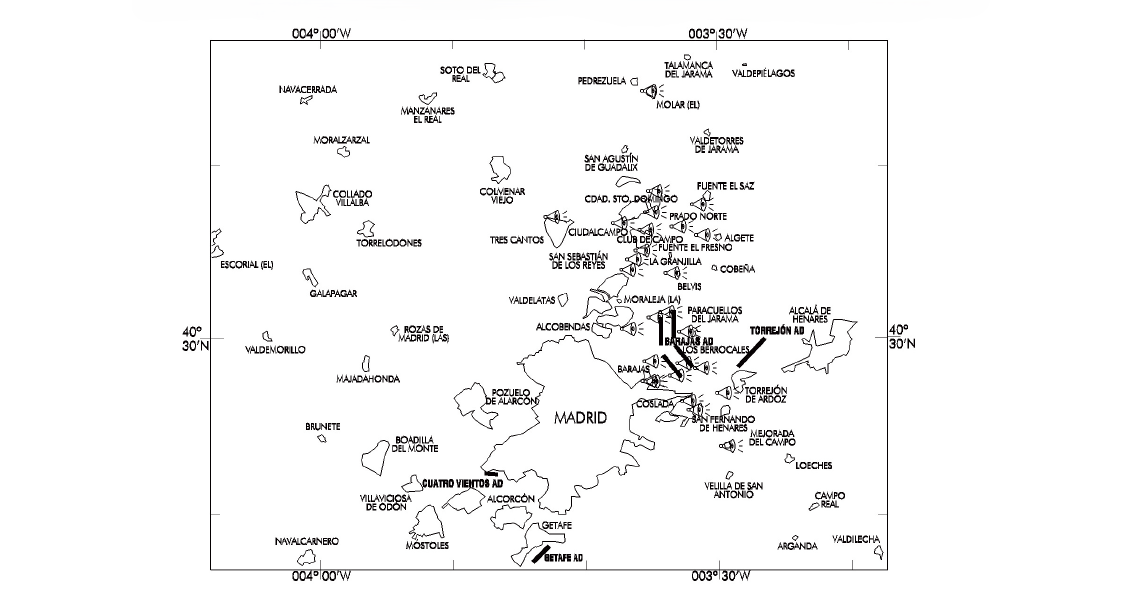
NAME | LOCATION | LATITUDE | LONGITUD |
|---|---|---|---|
TMR 01 | LA MORALEJA | 403034N | 0033640W |
TMR 02 | ALGETE | 403557N | 0033046W |
TMR 03 | SAN SEBASTIÁN DE LOS REYES | 403358N | 0033640W |
TMR 04 | FUENTE EL FRESNO | 403504N | 0033520W |
TMR 05 | CIUDAD STO. DOMINGO (S) | 403716N | 0033441W |
TMR 06 | FUENTE EL SAZ | 403742N | 0033102W |
TMR 07 | PARACUELLOS DEL JARAMA | 403025N | 0033204W |
TMR 08 | MEJORADA DEL CAMPO | 402348N | 0032858W |
TMR 09 | BELVIS | 403347N | 0033305W |
TMR 10 | SAN FERNANDO DE HENARES | 402553N | 0033125W |
TMR 11 | COSLADA (ESTACIÓN) | 402624N | 0033152W |
TMR 12 | BARAJAS (ALAM. OSUNA) | 402735N | 0033451W |
TMR 13 | BARAJAS (PUEBLO) | 402836N | 0033442W |
TMR 14 | THR RWY 32L | 402757N | 0033318W |
TMR 15 | THR RWY 32R | 402834N | 0033214W |
TMR 16 | TRES CANTOS | 403701N | 0034207W |
TMR 17 | THR RWY 18R | 403112N | 0033424W |
TMR 18 | EL MOLAR | 404417N | 0033446W |
TMR 19 | PLATAFORMA DIQUE SUR | 402731N | 0033437W |
TMR 20 | TORREJÓN DE ARDOZ | 402645N | 0032917W |
TMR 21 | CIUDAD STO. DOMINGO (N) | 403830N | 0033423W |
TMR 22 | THR RWY 18L | 403131N | 0033329W |
TMR 23 | LOS BERROCALES | 402818N | 0033053W |
TMR 24 | CIUDALCAMPO | 403640N | 0033702W |
TMR 25 | PRADO NORTE | 403623N | 0033251W |
TMR 26 | CLUB DE CAMPO | 403614N | 0033506W |
TMR 27 | LA GRANJILLA | 403430N | 0033610W |
FLIGHT PROCEDURES
ADJUSTMENT OF VERTICAL SPEED IN TMA MADRID
Aircraft in evolution shall adjust their vertical speed when approaching the assigned altitude or flight level. In these circumstances, vertical speed shall be reduced to 1500 ft per minute when approaching a vertical distance of 1000 ft above or below the assigned altitude or flight level.
DEPARTURES SPEED LIMITS
MAX IAS 250 kt until reaching 10000 ft.
ARRIVAL PROCEDURES
MODE OF OPERATION
The ATIS shall state the approach type used at all times:
INDEPENDENT PARALLEL APPROACHES IN USE.
DEPENDENT PARALLEL APPROACHES IN USE.
APPROACHES ON A SINGLE RUNWAY.
CLEARANCE LIMIT
Aircraft making a Standard Arrival (STAR), shall enter holding at the Clearance Limit if they do not receive subsequent clearance. Likewise, aircraft arriving at an IAF without subsequent clearance must also enter holding.
RADAR CONTROL ON APPROACH
Arrival traffic will be sequenced by radar vectoring through the use of ATS Surveillance Systems. The Clearance Limit may be replaced by clearance to a fix or final approach aid, or radar vectoring to direct the aircraft onto the final approach course or to a position from which an instrument approach may be completed. In the event of heavy traffic, the aircraft must wait for vectoring from the Clearance Limit in order to proceed to the IAF. Once the aircraft is under Radar Control, heading and flight/altitude level changes shall be made when instructed by Radar Control, except in the event of communications failure.
WAKE VORTEX SEPARATION
RECAT-EU wake turbulence separation applied for arrivals to LEMD. See ENR 1.8 for more information.
SPEED CONTROL
Speed Control is essential for safe and smooth operations, especially in heavy traffic conditions and during the final approach phase. Aircraft separation is intended to achieve maximum runway usage within the minimum separation parameters (including wake turbulence separation). These speeds are mandatory in order to ensure separation and the application of standardised approach procedures at MADRID/Adolfo Suárez Madrid-Barajas Airport. Unless otherwise instructed by ATC, pilots shall comply with the following speed restrictions on all runway configurations:
RWY | POSITION | ALTIAS |
|---|---|---|
18R/18L | CLEARANCE LIMIT | 220 KT |
RILKO or equivalent position | 220 KT | |
LULER or equivalent position | 220 KT | |
18L | MD623 | 200 KT |
MD620 | 185 KT | |
When intercepting LOC | 185 KT | |
32L/32R | CLEARANCE LIMIT | 220 KT |
FAFEQ or equivalent position | 220 KT | |
RUDBI or equivalent position | 220 KT | |
32L/32R/18R | When intercepting LOC | 200 KT |
ALL | 10 DME | 180 KT |
6 DME | 160 KT |
In the interests of precise separation, all speed restrictions must be adhered to with the greatest possible accuracy. Aircraft unable to comply with these speed restrictions due to weather conditions, aircraft performance or other operational reasons shall immediately inform ATC, indicating the speeds that may be used. Pilots shall not be exempt from complying with the previously assigned speed in the event that a new ATC clearance (unrelated to speed) is issued. Failure to comply with speed control instructions may result in aircraft being excluded from the planned approach sequence.
ABBREVIATED COMMUNICATIONS PROCEDURE
In communication transmissions to the East Approach Sector (FREQ 127.100 MHz) or to the West Approach Sector (FREQ 127.505 C), the call shall be limited to the flight CALL SIGN to avoid frequency congestion:
"Approach + Iberia 321"
UNINTENTIONAL CROSSING OF THE FINAL APPROACH COURSE
Once the pilot has received a radar vector that converges with the runway centre line heading at an angle of less than 70º, the pilot shall take the initiative of intercepting the ILS localizer or any radio aid replacing the LOC, unless previously instructed by ATC to cross the LOC or the runway centre line.
DELAY INFORMATION ON APPROACH
The expected approach time (EAT) shall be provided to an arriving aircraft whose landing is expected to be delayed by 10 minutes or more, or any other period of time as determined by the competent authority.
AIRCRAFT AIR/GROUND COMMUNICATIONS FAILURE PROCEDURES
In the event that an aircraft suffers a radio communications failure, it shall immediately squawk 7600. Depending on the aircraft's position at the time of failure, it shall proceed as follows:
ARRIVALS
During a STAR procedure before or at the Clearance Limit:
Maintain the last cleared altitude or level, proceed to the STAR Clearance Limit, execute two holding patterns and complete an ILS approach to the nearest runway.
During a STAR procedure after the Clearance Limit:
Before the IAF: Fly to the IAF, enter holding and after completing one pattern, descend to the approach start altitude and exit it, executing an ILS approach to the nearest runway.
After the IAF: continue the approach procedure to the nearest runway.
Traffic on radar vectors before the IAF:
Traffic must maintain the last cleared altitude or level and proceed directly to the IAF. Enter IAF holding and after completing a pattern, descend to the approach start altitude and exit it, executing an ILS approach to the nearest runway.
Vector traffic to the localizer:
Traffic completes the approach by proceeding to the localizer at the intercept altitude predicted on the approach chart.
MANOEUVRING AFTER A MISSED APPROACH:
If an aircraft suffers a communications failure during a missed approach manoeuvre, the following procedure shall be followed:
MISSED RWY 32L:
Fly according to the published procedure up to homing point.
Enter the holding pattern at 5000 ft.
Complete one pattern.
Maintain 5000 ft.
Fly to the IAF of the IAC 32L.
Complete a new approach and land.
MISSED RWY 32R:
Fly according to the published procedure up to homing point.
Enter the holding pattern at 6000 ft.
Complete one pattern.
Descend to 5000 ft.
Fly to the IAF of the IAC 32R.
Complete a new approach and land.
MISSED RWY 18R:
Fly according to the published procedure up to homing point.
Enter the holding pattern at 6000 ft.
Complete one hold.
Ascend, in the holding pattern, to 11000 ft.
Fly to the IAF of the IAC 18R.
Complete a new approach and land.
MISSED RWY 18L:
Fly according to the published procedure up to homing point.
Enter the holding pattern at 5000 ft.
Complete one hold.
Ascend, in the holding pattern, to 11000 ft.
Fly to the IAF of the IAC 18L.
Complete a new approach and land.
Aircraft without operational approval RNAV1:
If the aircraft without RNAV1 operational approval has already been instructed to proceed to a conventional radio aid or fix, or is receiving radar vectoring to the IAF of the approach, it shall maintain the last cleared altitude or level and proceed to that IAF. At the IAF, it shall descend to the approach start altitude and exit the IAF on approach manoeuvre.
If the aircraft has not yet received guidance to the IAF, it shall maintain the last cleared altitude or level and shall proceed to the IAF (SIE or PDT), descend to the start altitude of the conventional approach and perform the conventional approach manoeuvre to the runway that corresponds to it by geographical criteria.
In all the above cases where the aircraft completes the landing manoeuvre, it shall maintain position on the first taxiway section, ensuring a clear runway and await the arrival of an assistance vehicle.
DEPARTURES
During an SID procedure:
Continue the SID up to the TMA exit point, ascend to the last cleared altitude or level, or to the minimum safe altitude, whichever is higher, maintain this altitude or level for 7 minutes, continue to ascend according to the updated FPL.
During a departure with radar vectors:
Proceed in the most direct manner to intercept the last SID procedure received from ATC and continue the communications failure procedure during SID as indicated in a). If no SID clearance has been received, proceed to intercept the appropriate SID up to the TMA exit point and according to the updated FPL.
Aircraft without RNAV1 operational approval during a contingency departure or with radar vectors:
Proceed in the most direct manner to the TMA exit point in accordance with the communications failure procedure indicated in a), and join the appropriate ATS route.
CONTINUOUS DESCENT OPERATIONS
Depending on traffic situation, and if no need for interrupting the descent is foreseen, aircraft will be cleared to proceed to standard arrival (STAR), or by means of a "direct" clearance to an intermediate fix of the STAR, to the IAF, to an intermediate approach fix or to the IF, to the minimum altitude of the IAF or the IF of the instrument procedure (IAC) or the minimum ATC surveillance altitude of the sectors through which the direct route passes, whichever is the higher, so that the descent operation may be accomplished continuously.
LOW VISIBILITY PROCEDURES (LVP)
GENERAL
The Airport plans to conduct CAT II/III precision approach and landing operations and low visibility take-offs (RVR < 550 m) - LVTO on the following runways:
CAT II/III to runways: 32R, 32L, 18R and 18L.
LVTO from runways: 36R, 36L, 14R and 14L.
Besides general procedures, Low Visibility Procedures (LVP) will be applied subject to the following conditions:
Manoeuvring area: When any of the following circumstances occur:
The RVR value is equal to or less than 700 m on at least one transmissometer of the runways in use (*), or a minimum visibility value of less than 800 m is reported in the event the transmissometers are out of service, or
The cloud ceiling is below 300 ft (as reported in the METAR/SPECI), or cloud height is less than 300 ft on at least one ceilometer located at the thresholds of the runways in use for landing.
(*) Given the layout and extension of the aerodrome, the TWR Supervisor, following coordination with the Service Executive of the airport, will be able to evaluate the possibility of not implementing the LVP in the event that the RVR values are less than 700 m (but never less than 600 m) in one of the RVRs at the end of one of the take-off runways, with good visibility in the rest of the aerodrome.
Apron:
When visibility less than or equal to 400 m is reached, measured by visibility measuring equipment on the apron:
or if this value is not available, the RVR value will be adopted, measured by the runway transmissometer nearest to the affected apron,
or the same prevalent or minimum visibility value if the measure equipments are out of service.
When the conditions for LVP activation do not occur in T-123 Apron, but the RVR value measured by the transmissometer located at THR 32L is less than 400 m, LVP in Ramp 7 will be activated.
Pilots will be informed about the application of Low Visibility Procedures by ATIS.
Any notified or detected incidence that may affect the LVP (in relation to the aids of instrumental and visual approach, take-off and taxiing, the anti-intrusion systems in critical areas, sensitive areas and active runways and any available aid) will be immediately communicated to aircraft and ATC services involved and the Apron Management Service (SDP) in its responsability area.
Runway visual range values will be supplied directly by ATC services in accordance with the following:
RVR TDZ: Reading corresponding to the Touchdown Zone.
RVR MID: Reading corresponding to the runway midpoint.
RVR END: Reading corresponding to the runway end.
Landing clearance will be supplied when ILS sensitive areas are free, until the aircraft on approach is located at 2 NM from touchdown point.
The LVP in the manoeuvring area will be cancelled when the following accumulative values would be reached:
The RVR value is greater than 800 m on all transmissometers (**), or the same minimum visibility value (as reported in the METAR / SPECI) if all transmissometers are out of service.
The cloud ceiling is equal to or greater than 400 ft (in the METAR / SPECI) or the cloud height is equal to or greater than 400 ft on all runway thresholds ceilometers.
When there is a definite improvement trend indicated by:
a TAF forecasting, without PROB, visibility equal to or greater than 1500 m and a cloud ceiling equal to or greater than 800 ft; or
a TREND forecasting VIS ≥ 1500 m or cloud ceiling ≥ 800 ft, followed by a TAF, without PROB, showing the same conditions.
(**) Given the layout and extension of the aerodrome, the TWR Supervisor, following coordination with the Service Executive of the airport, will be able to evaluate the possibility of cancelling the LVP in the event that the RVR values are less than 800 m (and never less than 600 m) in one of the RVRs at the end of one of the take-off runways, as long as the rest of the conditions for cancelling LVP are met.
The LVP in each apron will be cancelled when the values of visibility measured by both equipments are above 400 m, or this value is not available, the RVR value will be adopted, measured by the runway transmissometer nearest to the affected apron and when the TREND or TAFOR, without PROB, forecast an increase in visibility greater than 1000 m.
The LVP in ramp 7 will be cancelled when the transmissometer located at THR 32L is more than 400 m and when the TREND or TAFOR forecast an increase in visibility greater than 1000 m.
GROUND MOVEMENT
Pilots and drivers shall proceed to verify the moving element position at all times, especially in intersections, making sure that taxiing is being executed under total safety conditions. In the event of being disoriented or in doubt, pilots shall stop the moving element, notify (including last known position) ATC or the Apron Management Service (SDP) in its area of responsability and request the assistance of a "FOLLOW ME" vehicle. It is the pilot or driver responsability to maintain the appropiate separation with the "FOLLOW ME" vehicle.
In situations in which the pilot doubts the aircraft position relative to the manoeuvring area, but recognises that the aircraft is on a runway, the pilot shall notify ATC immediately (including the last known position), unless ATC advise otherwise and if the pilot can locate an appropiate nearby taxiway, the pilot shall vacate runway as soon as possible; and shall then stop the aircraft.
In the case of the disorientation of a vehicle or convoy in the manoeuvring area, it shall be reported to ATC (including the last known position) and, unless otherwise advised by ATC the driver shall vacate the runway, taxiway or any other part of the manoeuvring area to move away to a safe distance as soon as possible and stop the vehicle or convoy. In the case of failure, and if possible, the same procedure shall be followed.
Unless otherwise instructed by of ATC or the Apron Management Service (SDP) in its area of responsability, all aircraft will follow the standard taxiing routes except:
Transfer point GATE 5 will not be used, unless authorised by ATC, prior coordination between ATC and SDP.
In north configuration, exits from PRKG 178 to 186 and 205 to 209 shall be carried out via C7, E3, E2, E1, A6, A5, C6, M6, …M10.
In north configuration, exits from PRKG 200 to 204 shall be carried out via C11, E3, E2, E1, A6, A5, C6, M6, …M10.
In north configuration, exits from PRKG 210 to 227 shall be carried out via E2, E1, A6, A5, C6, M6, …M10.
In north configuration, exits from PRKG 258 to 264 shall be carried out via E2, E1, A6, A5, C6, M6, …M10.
In south configuration, entries to PRKG 258 to 264 shall be carried out via M8 … M6, C6, A5 … A7, F2, F3.
Aircraft shall comply with OPERATION OF MODE S TRANSPONDER WHEN THE AIRCRAFT IS ON THE GROUND in accordance with AIP-España AD 2-LEMD.
When LVP is activated in the manoeuvring area, the movements of towed aircraft in the manoeuvring area will be reduced to a minimum, and crossing the active runways will not be authorised in any case. The pilot-in-command or the operator of the towed aircraft must switch on the mode S transponder.
In the manoeuvring area if the RVR value is lower than 400 m, or if LVP at the apron are in force, the movements of towed aircraft in the manoeuvring area will be reduced to a minimum and will be subject to express request by the Service Executive. Aircraft towed in these conditions shall be accompanied by the properly equipped "FOLLOW ME" vehicle and TWR or the Apron Management Service (SDP) in its area of responsability will decide when to authorise it.
In low visibility conditions, the following measures will be taken:
During the activation of low visibility procedures on the apron:
Stands:
All aircraft parked in a stand that requires a push-back manoeuvre shall follow the instructions once they have received ATC clearance (or the approval of the Apron Management Service (SDP), when being in its area of responsibility). Simultaneous push-back manoeuvres will not be authorised for contiguous stands.
Entry or exit to/from the following stands will be carried out under the following conditions:
Access to PRKG T1, T2 and T3 will take place, regardless of the time, via A5, C5 in north configuration and via M5, C5 in south configuration.
Push-back manoeuvre will be controlled by TOAM, afterwards aircraft will be moved forward by the towing tractor until the service road has been vacated, on the following stands:
Ramp 1: PRKG T22 and T23 (nosing to NW);
Ramp 2: PRKG T20, T20W and T21 (nosing to SE).
Push-back manoeuvre will be controlled by TOAM, afterwards aircraft will be moved forward by the towing tractor up to T15, ensuring that the intermediate holding position has been vacated, on the next stands:
Ramp 2: PRKG T14, T15 and T16 (nosing to N).
Push-back manoeuvre will be controlled by TOAM, afterwards aircraft will be moved forward by the towing tractor up to T12, ensuring that the intermediate holding position has been vacated, on the next stands:
Ramp 3: PRKG T12, T13 and T13W (nosing to S).
The entries and exits of PRKG from 500 to 502 and 584 to 586 will be carried out with the guidance of the "FOLLOW ME" vehicle.
In the following stands the operations are prohibited except with express authorisation of the Service Executive and with the guidance of the "FOLLOW ME" vehicle:
Departures:
Apron T-123: PRKG 70, 71.
Prohibited entries and exits:
Ramp 1: PRKG from T36;
Ramp 4: PRKG 171 to 175;
Ramp 24: PRKG 700 to 722.
Service roads
The following service roads will be closed:
LVP in apron T-123:
SV1 in its intersection with C1, with C2 and with I10; SV3, SV6, SV8, SV10, SV11 in its intersection with A5, SV13, SV15, SV16, SV18, SV19, SV22, SV35, SV36 in its intersection with C7 (access to PRKG 210 to 227) and SV37.
LVP in Ramp 7:
SV35, SV36 in the intersection with C7 (access to PRKG 210 to 227), SV37 and SV38.
LVP in apron T-4:
SV54, in the segment delimited between the remote PRKG 412 to 419, and the outer road of the apron;
SV53 (access to the remote PRKG 420 to 432);
SV52, in the segment delimited between the remote PRKG from 432 and 434, and the remote PRKG 446 and 448.
LVP in apron T-4S:
SV73 (access to the remote PRKG 600 to 610);
SV72, in the segment delimited between the remote PRKG 610 and 612.
Meeting points
The meeting points are located at:
Apron T-123:
For Ramp 0: From PRKG 20 to 29: service road SV6, near PRKG 21.
For Ramp 1: From PRKG 7 to 9: service road SV1, near PRKG 8.
For access to PRKG 20 to 29: by the side of roundabout near the SEI building.
For Ramp 4 on SV11: near PRKG T2.
For PRKG 210 to 227: EPA (Equipment Parking Area) located between the service road and PRKG 220.
For PRKG 258 to 264: service road SV38 near PRKG 264.
For access to PRKG 258-264: EPA (Equipment Parking Area) located between the service road and PRKG 220.
T-4 apron:
For remote PRKG 420 to 432, ESA (Equipment Standby Area) located between service road and PRKG 340 and EPA (Equipment Parking Area) between PRKG 428 and 430.
T-4S apron:
For PRKG 600 to 610, bay situated between service road close to the PRKG 554 and EPA (Equipment Parking Area) between remote PRKG 606 and 608.
Arrivals
RWY 32R, 32L, 18R and 18L (depending on facilities requested are in service), are authorised for CAT II/III operations by those operators whose operational minima have been accepted or assigned by the Dirección General de Aviación Civil.
Aircraft that have already landed must vacate the runway in use by some of the taxiways specified below, except otherwise authorised by ATC:
LANDING RUNWAY | REMARKS |
|---|---|
32L | L2, L3, L4, L5 Preferably L2 & L4 for arrivals to T-4. L7 in the case of activation of LVP due to cloud ceiling only. |
32R | K3, K4, K5 Traffic intending to vacate via K3 shall report to ATC as soon as possible. |
18L | Y3, Y4, Y5 Traffic intending to vacate via Y3 shall report to ATC as soon as possible. |
18R | Z-7, Z-8, Z-10 |
Whenever it is possible, the minimum runway occupancy time, criteria detailed, as shown in the corresponding table at item 20, AD 2-LEMD will be used.
On TWR request, when leaving the sensitive area of the runway, pilots shall notify: "Sensitive area vacated" and TWY used.
Aircraft A380 shall notify "sensitive area vacated" having completely leaved the taxiway, or in the case of RET L2 or L4 when crossing the first intermediate holding position L2-1 or L4 with L42 respectively.
Aircraft vacating the sensitive area have priority over all other aircraft taxiing in the vicinity.
Aircraft landing on RWY 32L, 32R, 18L or 18R will abandon the runway by the appropriate TWY, following the taxiway centre line lights (1) until vacating the LSA, where they will receive GMC instructions or will stop if they have not been given instructions. (1) The green/yellow taxiway centre line lights begin at the runway centre line and finish at the critical/sensitive ILS area perimeter (ICAO Annex 14 item 5.3.16.7).
If there is no RVR available on an arrival runway, that runway must not be used when LVP are in force.
Departures
Low visibility take-offs are authorised from RWY 36R, 36L, 14R and 14L, according to the tables of minima AD operations as shown in appendix 1 of EU-OPS 1430, of the Regulation (CE) 859/2008, and they are interpreted with the criteria and exceptions gathered in said document.
The Airport has no lateral guidance system for guided take-offs.
In compliance with AMC1 SPA.LVO.100 (a) requirements of Regulation (EU) 965/2012 of 5th October 2012, LVTO operations are not permitted with visibility conditions less than 75 metres (RVR< 75 m).
Pilots in command will request from ATC the start-up of engines when RVR values are equal to or higher than their minimum for take-off.
On receipt of the corresponding ATC clearance (or approval of the Apron Management Service (SDP) if the aircraft is inside its area of responsability) aircraft positioned in a stand that requires push-back manoeuvre will follow their instructions. Simultaneous push-back shall not be authorised for adjacent stands.
Aircraft will hold short and obey the signs from the stop bar lighting when cleared to taxi to a runway-holding position of the runway in use.
If there is no RVR available on an departure runway, that runway must not be used when LVP are in force.
COMMUNICATIONS FAILURE
Whenever an aircraft or vehicle operating in the movement area experiences a communications failure it will comply as follows:
Departing aircraft: will continue through the assigned route until stopping at an intermediate holding position or its clearance limit taking extreme caution to avoid detours. Aircraft shall remain at this point and wait for the "FOLLOW ME" vehicle to arrive in order to be guided to the stand or holding position designated by the appropriate authority.
Arriving aircraft: if the aircraft has just landed, it will hold its position in the first segment of the taxiway where the ILS sensitive area is vacated, and wait for the arrival of an assistance vehicle. If the aircraft has already received ATC taxiing clearance, it shall continue along the assigned route to the ATC clearance limit, taking special caution, where it shall hold position and wait for the arrival of an assistance vehicle.
This involves a vehicle, it shall vacate the runway, taxiways or any other part of the manoeuvring area if it is in it (provided the driver is assured he can do it and he is not absolutely disoriented) and afterwards he shall stop the vehicle holding position and waiting for the assistance vehicle or aid means.
ATS SURVEILLANCE SYSTEM
It is used in the provision of the aerodrome control service to perform the following functions:
Supervision of the flight path of aircraft on final approach;
Supervision of the flight path of other aircraft in the vicinity of the aerodrome;
Establishment of separation, as defined in the R.C.A. section 4.6.7.3, between successive departing aircraft.
In the event that only the Barajas radar is available: Function b) will be suspended.
All the functions above will be suspended in the event of a simultaneous unavailability of all three radars: Paracuellos 1, Paracuellos 2 and Barajas.
VISUAL DEPARTURE PROCEDURE FOR IFR FLIGHTS
Under certain meteorological conditions (cumulonimbus clouds, thunderstorms, etc.) which, for safety reasons, prevent the use of published Standard Instrument Departures (SIDs) and contingency departures, IFR flights may request a "visual departure" from ATC, subject to the following conditions:
Between the beginning of morning civil twilight and the end of evening civil twilight.
Meteorological conditions in the take-off direction and initial climb path must permit visual flight up to the Minimum Radar Altitude.
Once lined up on the runway, the pilot shall propose to ATC a heading that ensures a safe departure. If a subsequent deviation from the approved heading becomes necessary, the pilot shall notify ATC accordingly.
The pilot shall be responsible for ensuring obstacle clearance until reaching the Minimum Radar Altitude.
Visual departure will be authorized according to the following heading scheme for each configuration:
CONFIGURATION | HEADINGS FROM | HEADINGS UP TO |
|---|---|---|
RWY 14R/14L | 130º | 170º |
RWY 36R/36L | 340º | 020º |
Noise abatement procedures published in AIP LEMD AD 2.21 that are incompatible with visual departures shall not apply during such operations.
ADDITIONAL INFORMATION
BIRD CONCENTRATION AREAS
Vulture and stork concentration zones outside the airport, intercepting climb and approach paths.
Zone with higher presence of small birds and medium-sized birds of prey.
Corridor zone for waterfowl, storks, hirundinids, and medium-sized birds of prey.
Movement of large flocks of pigeons in both directions during mornings and afternoons.
MOST RELEVANT HAZARDOUS SPECIES CALENDAR
| MAX Weight (gr) | Jan | Feb | Mar | Apr | May | Jun | Jul | Aug | Sep | Oct | Nov | Dec |
|---|---|---|---|---|---|---|---|---|---|---|---|---|---|
Eurassian black vulture | 12500 | ||||||||||||
Griffon vulture | 11000 | ||||||||||||
Spanish imperial eagle | 3500 | ||||||||||||
White booted eagle | 975 | ||||||||||||
Red kite | 1221 | ||||||||||||
Black kite | 941 | ||||||||||||
Common buzzard | 1364 | ||||||||||||
Western Marsh harrier | 800 | ||||||||||||
Eagle owl | 4200 | ||||||||||||
Common kestrel | 314 | ||||||||||||
White stork | 4400 | ||||||||||||
Common crane | 6100 | ||||||||||||
Grey heron | 2073 | ||||||||||||
Gulls | 2272 | ||||||||||||
Waterfowls | 1640 | ||||||||||||
Wood pigeon | 690 | ||||||||||||
Starlings | 100 | ||||||||||||
Finches | 72 | ||||||||||||
Swallows | 52 |
Low | |
Moderate | |
High | |
Very high |
ENGINEERED MATERIAL ARRESTING SYSTEM (EMAS)
DESCRIPTION
This system improves operational safety in the case that aircraft go off the end of the runway.
It consists of a material composed of blocks of porous concrete located in the extension of the runway end from the threshold and that will be crushed by the weight of the aircraft that exceeds the runway threshold. The aircraft is decelerated by the strength of the crushable material and safely stopped within the limits of the runway end safety area.
LOCATION
Engineered Material Arresting System is installed in the RESA of RWY 32L and 32R.
The dimensions of these areas are: width 69.2 m / 227 ft and length 63.1 m / 207 ft, located at:
RWY 32L: 78 m before the antennas of the locator, being these antennas at 3318 m from threshold.
RWY 32R: 9 m before the antennas of the locator, being these antennas at 3300 m from threshold.
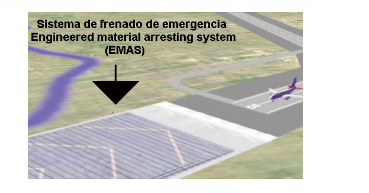
RULES OF USE
After the system has been used by an aircraft, it must be restored to assure its breaking specifications for future uses. For this reason, the company whose aircraft has overrun the runway end, must have the respective insurance, covering damages including the repair of the Engineered material arresting system (EMAS).
Besides the runway end safety area (RESA) restrictions, where this system is installed, and due to the characteristics of this system, the traffic of any vehicle or people in the area is strictly prohibited in all cases.
ARTIFICIAL TURF IN UNUSABLE AREAS
Some of the Unusable paved areas are covered with artificial turf.
AERONAUTICAL CHARTS RELATED TO AN AERODROME
The list of charts related to the aerodrome can be found on the link below:
VISUAL SEGMENT SURFACE (VSS) PENETRATION
Not applicable.